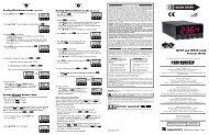
- Page 2: Additional products fromNEWPORT Ele
- Page 7 and 8: Table of ContentsSECTION 19 FACTORY
- Page 9 and 10: FiguresFigure 7-9 DC Connector Wiri
- Page 11 and 12: Introduction 11.1 DESCRIPTION1.2 FE
- Page 13 and 14: Introduction 1SERIAL COMMUNICATIONS
- Page 15 and 16: Unpacking 21 Rear ProtectiveCover w
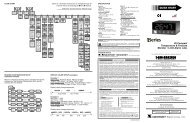
- Page 17 and 18: Parts of the Meter 44.1 FRONT OF TH
- Page 19 and 20: Parts of the Meter 4ITEMDESCRIPTION
- Page 21: Parts of the Meter 4P2 / CABLE CONN
- Page 29 and 30: Setup 55.2.4 How to Access JumpersT
- Page 31 and 32: Setup 5P7P6P10ADBCES1PIN 1Figure 5-
- Page 33 and 34: Setup 5S5AS4BACEGABS8S1AS2AJ20PIN 1
- Page 35: Setup 5WARNING: Do not “turn-on
- Page 39 and 40: Jumper Positions 6DISPLAYBDDCBS3ASI
- Page 41 and 42: Signal and Power Input Connections
- Page 43 and 44: Signal and Power Input Connections
- Page 45 and 46: Scaling to Display Engineering Unit
- Page 47 and 48: Scaling to Display Engineering Unit
- Page 49 and 50: Scaling to Display Engineering Unit
- Page 51 and 52: Scaling to Display Engineering Unit
- Page 53 and 54: Scaling to Display Engineering Unit
- Page 55 and 56: Scaling to Display Engineering Unit
- Page 57 and 58: Scaling to Display Engineering Unit
- Page 59 and 60: Scaling to Display Engineering Unit
- Page 61 and 62: Scaling to Display Engineering Unit
- Page 63 and 64: Scaling to Display Engineering Unit
- Page 65 and 66: Scaling to Display Engineering Unit
- Page 67 and 68: Meter Function Menus 9EXPLANATION O
- Page 69 and 70: Meter Function Menus 9MENU MIN/MAX*
- Page 71 and 72: Meter Function Menus 9MENU MIN/MAX*
- Page 73 and 74: Meter Function Menus 99.2 METER FUN
- Page 75 and 76: Meter Function Menus 99.2.3 RDG SC
- Page 77 and 78: 9.2.4 IN CNF (Input Configuration)I
- Page 79 and 80: Meter Function Menus 9** The ‘MIN
- Page 81 and 82: Meter Function Menus 99.2.7 CNT BY
- Page 83 and 84: Meter Function Menus 99.2.9 FIL TI
- Page 85 and 86: Meter Function Menus 9* The ‘MIN
- Page 87 and 88:
Meter Function Menus 99.2.12 AL FNC
- Page 89 and 90:
Meter Function Menus 99.2.14 SP DB
- Page 91 and 92:
Meter Function Menus 99.2.17 OT.SC.
- Page 93 and 94:
Meter Function Menus 99.2.19 SERCNF
- Page 95 and 96:
Meter Function Menus 9MENU MIN/MAX/
- Page 97 and 98:
Meter Function Menus 9* The ‘MIN
- Page 99 and 100:
SETPOINTS/ALARMSSetpoints/Alarms 10
- Page 101 and 102:
Setpoints/Alarms 1010.2 UNLOCKING T
- Page 103 and 104:
Setpoints/Alarms 10SP3 = 100SP1-SP3
- Page 105 and 106:
Setpoints/Alarms 107. “ALC.7=0”
- Page 107 and 108:
Setpoints/Alarms 1010.10 “OUT.CNF
- Page 109 and 110:
ANALOG OUTPUT OPTIONAnalog Output O
- Page 111 and 112:
Analog Output Options 124. Store th
- Page 113 and 114:
Analog Output Options 1212.6 FILTER
- Page 115 and 116:
BCD Option 13Figure 13-2 shows the
- Page 117 and 118:
BCD Option 1313.4 50-LINE CABLE COM
- Page 119 and 120:
BCD Option 1313.11 SELECT DATA POLA
- Page 121 and 122:
Relay Options 14Figure 14-2 below s
- Page 123 and 124:
RS-232 or RS-485 Option Board 1515.
- Page 125 and 126:
RS-232 or RS-485 Option Board 1515.
- Page 127 and 128:
External Control Lines 1616.3 VALLE
- Page 129 and 130:
Troubleshooting 17TROUBLESHOOTING -
- Page 131 and 132:
“ERR 02”POSSIBLE CAUSE:TO CORRE
- Page 133 and 134:
Specifications 1818.1 CURRENT INPUT
- Page 135 and 136:
POWER RATING FORRESISTIVE LOADS:DUA
- Page 137 and 138:
FLASHING MESSAGESDURING PROGRAMMING
- Page 139 and 140:
Decimal Point “DEC PT” Position
- Page 141 and 142:
JUMPER POSITIONS:CurrentS1: _______
- Page 143 and 144:
Record your Setup Values 20Output S
- Page 145:
For immediate technical or applicat