Design of the Third Karnaphuli Bridge D. Astin - Bangladesh Group ...
Design of the Third Karnaphuli Bridge D. Astin - Bangladesh Group ...
Design of the Third Karnaphuli Bridge D. Astin - Bangladesh Group ...
- No tags were found...

Create successful ePaper yourself
Turn your PDF publications into a flip-book with our unique Google optimized e-Paper software.
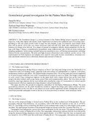
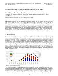
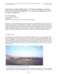
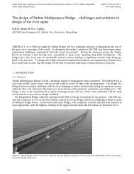
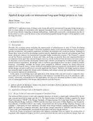
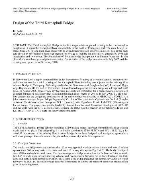
IABSE-JSCE Joint Conference on Advances in <strong>Bridge</strong> Engineering-II, August 8-10, 2010, Dhaka, <strong>Bangladesh</strong>. ISBN: 978-984-33-1893-0Amin, Okui, Bhuiyan (eds.)www.iabse-bd.org<strong>Design</strong> <strong>of</strong> <strong>the</strong> <strong>Third</strong> <strong>Karnaphuli</strong> <strong>Bridge</strong>D. <strong>Astin</strong>High-Point Rendel Ltd., UKABSTRACT: The <strong>Third</strong> <strong>Karnaphuli</strong> <strong>Bridge</strong> is <strong>the</strong> first major cable-supported crossing to be constructed in<strong>Bangladesh</strong>. It spans <strong>the</strong> <strong>Karnaphuli</strong>River immediately to <strong>the</strong> north <strong>of</strong> Chittagong port. The main bridge includesthree 200 m long main river spans with an extradosedprestressed concrete single cell box girder deckconstructed by <strong>the</strong> balanced cantilever method.The bridge is founded on alluvial soil affected by deep soilliquefaction and river scour. The foundations <strong>of</strong> <strong>the</strong> main bridge incorporate 3 m diameter bored cast in situpiles which were base grouted post-construction. Construction <strong>of</strong> <strong>the</strong> bridge commenced in July 2007 and <strong>the</strong>crossing was opened to traffic in July 2010.1 PROJECT INCEPTIONIn November 2001, a report commissioned by <strong>the</strong> Ne<strong>the</strong>rlands’ Ministry <strong>of</strong> Economic Affairs, examined severalroute options for a third crossing <strong>of</strong> <strong>the</strong> <strong>Karnaphuli</strong> River including one adjacent to <strong>the</strong> existing ShahAmanat <strong>Bridge</strong> in Chittagong. Following studies by <strong>the</strong> Government <strong>of</strong> <strong>Bangladesh</strong> (GoB) Roads and HighwaysDepartment (RHD) and its Consultants, it was decided to procure <strong>the</strong> new bridge on a design and buildbasis. In August 2005, tenders were invited from pre-qualified contractors for a bridge having a prestressedconcrete extradosed box girder deck with minimum main span lengths <strong>of</strong> 200 m. In July 2006, a US$50 millioncontract for <strong>the</strong> design and construction <strong>of</strong> <strong>the</strong> entire project was awarded to MBEC-ACL-COPRI JV, ajoint venture between Major <strong>Bridge</strong> Engineering Co. Ltd (China), Al-Amin Construction Co. Ltd (<strong>Bangladesh</strong>)and Copri Construction Enterprises W.L.L (Kuwait), with High-Point Rendel Ltd (HPR) (UK) designerfor <strong>the</strong> bridge. The project was jointly funded by Kuwait Fund for Arab Economic Development (KFAED)and <strong>the</strong> GoB, with <strong>the</strong> RHD as main client. Benaim Ltd (UK) was <strong>the</strong> checker <strong>of</strong> <strong>the</strong> definitive design andKEI-BCL-TAEP-STUP JV were <strong>the</strong> supervising consultants2 SCHEME DESCRIPTION2.1 LocationThe <strong>Third</strong> <strong>Karnaphuli</strong> <strong>Bridge</strong> scheme comprises a 950 m long bridge, approach embankments, river trainingworks and a toll plaza. The bridge (Fig. 1 - mid point coordinates 22º19’33.59”N and 91º51’11.33”E), is located50 m upstream <strong>of</strong> <strong>the</strong> existing Shah Amanat <strong>Bridge</strong>. It has been designed with navigation spans whichwill allow passage <strong>of</strong> vessels to reach <strong>the</strong> planned expansion <strong>of</strong> port facilities upstream.2.2 Principal DimensionsThe whole new bridge crossing consists <strong>of</strong> a 120 m long approach viaduct section (subdivided into 20 m longspans), three 200 m long main river spans and two 115 m long side spans (Fig. 2 & 3). The bridge is alignedon a 3200 m radius horizontal curve. The dual carriageway bridge carries four traffic lanes <strong>of</strong> 3.65 m width,two 1.65 m wide lanes for slow-moving vehicles and two footways. Services run in ducts located in <strong>the</strong> footwaysand in <strong>the</strong> bridge central reservation. The overall deck width, including <strong>the</strong> central stay cable tower andfootways, is 24.47 m. The main bridge deck was constructed in situ by <strong>the</strong> balanced cantilever method usingpairs <strong>of</strong> travelling forms.257
Figure 1.Location PlanFigure 2.Elevation <strong>of</strong> <strong>Bridge</strong>Figure 3.Plan <strong>of</strong> <strong>Bridge</strong>258
2.3 SubstructureEach <strong>of</strong> <strong>the</strong> four main river piers (i.e. Piers 7 to 10) is founded on four 3 m diameter vertical piles (in squareconfiguration) <strong>of</strong> maximum 77.0 m length (from base <strong>of</strong> pile cap). The six approach viaduct piers and <strong>the</strong>north abutment are each supported by a row <strong>of</strong> four parallel 1.5 m diameter vertical piles <strong>of</strong> maximum 52.4 mlength (from ground level). The south abutment is founded on two parallel lines <strong>of</strong> six 1.5 m diameter verticalpiles <strong>of</strong> maximum 54.0 m length. All piles are reinforced concrete bored (under bentonite slurry) cast in situand are installed with sonic logging tubes. The piles are founded in alluvial strata partially affected by maximum30 m deep soil liquefaction and river scour. The toe <strong>of</strong> <strong>the</strong> main pier piles was base grouted postinstallationto improve <strong>the</strong>ir performance and for quality assurance.3 SITE INFORMATION AND DESIGN CODES3.1 SiteThe site lies in <strong>the</strong> flat coastal region <strong>of</strong> Chittagong at <strong>the</strong> foot <strong>of</strong> <strong>the</strong> Chittagong Hills. The <strong>Karnaphuli</strong>Riverdrains part <strong>of</strong> this hill system and deposits alluvial and deltaic strata in <strong>the</strong> adjoining flat plain. At <strong>the</strong> bridgelocation, <strong>the</strong> <strong>Karnaphuli</strong>River generally flows in a main channel approximately 280 m wide. It extends <strong>the</strong>950 m width <strong>of</strong> <strong>the</strong> flood channel, between <strong>the</strong> riverbanks on each side, during <strong>the</strong> annual monsoon season. At<strong>the</strong> project site, <strong>the</strong> river is tidal and fluctuates in level by up to 5.9 m.3.2 <strong>Design</strong> StandardsIn accordance with <strong>the</strong> RHD’s requirements, <strong>the</strong> tender and definitive design <strong>of</strong> <strong>the</strong> permanent works for <strong>the</strong>entire bridge was carried out following AASHTO LRFD (2004) and British Standard BS 5400 (1990) as describedbelow. The standards for <strong>the</strong> construction materials, ground investigations and in situ and laboratorytesting were AASHTO and ASTM. O<strong>the</strong>r compatible codes and technical literature were adopted for specificdesign issues not covered by <strong>the</strong> main standards. The entire bridge was designed following <strong>the</strong> strength andserviceability limit state approach.According to <strong>the</strong> <strong>Bangladesh</strong> National Building Code (1993), <strong>the</strong> newbridge site lies within seismic Zone-2, corresponding to a 100 years return ground surface acceleration <strong>of</strong>0.05g. The design seismic zone coefficient (Z) for <strong>the</strong> area is 0.15 for horizontal excitation and 0.7 x Z forvertical excitation. As <strong>the</strong> bridge will become an important link in <strong>the</strong> <strong>Bangladesh</strong>i national highway network,it is classified as an “essential” structure as defined in AASHTO LRFD (2004) and consequently had to bedesigned accordingly in terms <strong>of</strong> strength and serviceability.4 SUBSTRUCTURE GEOTECHNICAL DESIGN4.1 GeneralThe design <strong>of</strong> <strong>the</strong> piled foundations was carried out according to AASHTO LRFD (2004). This standard permits<strong>the</strong> use <strong>of</strong> both empirical and “rational” design formulae (i.e. formulae adopting strength and stiffnessvalues as input data) to calculate vertical pile capacity. Empirical formulae are <strong>of</strong>ten based on “local” experiencewhich depends, amongst o<strong>the</strong>r factors, on <strong>the</strong> specific ground conditions, <strong>the</strong> method <strong>of</strong> pile construction,and pile length and diameter. Despite <strong>the</strong> considerable amount <strong>of</strong> reliable SPT data available for <strong>the</strong> site,<strong>the</strong> use <strong>of</strong> empirical design formulae was not deemed to be appropriate given <strong>the</strong> peculiarity <strong>of</strong> <strong>the</strong> local geologicalsequence and <strong>the</strong> unusual large diameter <strong>of</strong> <strong>the</strong> main pier piles. Instead <strong>the</strong> design <strong>of</strong> <strong>the</strong> piles for verticalcapacity was carried out using “rational” formulae and <strong>the</strong> geotechnical properties input for <strong>the</strong> soil werederived from <strong>the</strong> laboratory test results and site specific correlations with <strong>the</strong> SPT data.4.2 Base GroutingThe ground investigations carried out during <strong>the</strong> initial phase <strong>of</strong> <strong>the</strong> design had revealed that <strong>the</strong> site groundconditions are vertically and laterally variable, and partly unforeseeable. There was a risk that <strong>the</strong> workingpiles could be founded on compressible strata with poor resistance. The preliminary calculations indicatedthat <strong>the</strong> 3 m diameter main pier working piles, due to <strong>the</strong>ir large diameter, would provide roughly 38% <strong>of</strong><strong>the</strong>ir resistance in end-bearing. The contribution <strong>of</strong> <strong>the</strong> shaft to pile resistance, despite <strong>the</strong> “considerable” pilelength, was proportionally less due to <strong>the</strong> potential for deep scour and soil liquefaction. In order to guarantee<strong>the</strong> full design performance <strong>of</strong> <strong>the</strong> piles in end-bearing it was decided to carry out post-installation compactionbase grouting. This involved <strong>the</strong> slow injection at high pressure <strong>of</strong> a viscous grout mix to “compact” <strong>the</strong>259
strata and debris (resulting from <strong>the</strong> pile shaft excavation) located below and at <strong>the</strong> pile toe, thus mobilising<strong>the</strong> full pile end bearing at a smaller displacement. This is a critical aspect when using large diameter piles.The peak pile end-bearing resistance may be assumed to be mobilised at 10% <strong>of</strong> <strong>the</strong> pile diameter (i.e. 300mm here), at which displacement shear will already have occurred along <strong>the</strong> shaft, thus providing very limitedresidual resistance, and <strong>the</strong> pile settlement will also already be excessive. Base grouting will also restore <strong>the</strong>original in situ strength <strong>of</strong> <strong>the</strong> soil which was expected to be affected by <strong>the</strong> anticipated lengthy excavationunder bentonite slurry <strong>of</strong> <strong>the</strong> deep, large diameter pile shafts. A particular arrangement <strong>of</strong> six U-shaped“tubes-à-manchette” cast into <strong>the</strong> toe <strong>of</strong> <strong>the</strong> pile was adopted to base grout a substantial proportion <strong>of</strong> <strong>the</strong>large pile footprint. The effectiveness <strong>of</strong> <strong>the</strong> base grouting was verified by comparing <strong>the</strong> results <strong>of</strong> three basegrouted test piles to <strong>the</strong> un-grouted test pile at Pier 3. The compaction grouting was found to be very effectiveinrestoring and indeed improving <strong>the</strong> original in situ soil resistance. The pile testing also showed that some <strong>of</strong><strong>the</strong> grout injected at <strong>the</strong> toe <strong>of</strong> <strong>the</strong> piles had randomly migrated upwards from <strong>the</strong> pile toe along <strong>the</strong> shaft interface<strong>of</strong>ten substantially improving <strong>the</strong> frictional resistance <strong>of</strong> <strong>the</strong> bottom 3-4 m <strong>of</strong> <strong>the</strong> piles. The advantages <strong>of</strong>using compaction grouting were also confirmed by comparing <strong>the</strong> sonic logging integrity test results for <strong>the</strong>non-base-grouted test pile at Pier 3 to <strong>the</strong> o<strong>the</strong>r three base-grouted test piles. The non-base-grouted pileshowed a “s<strong>of</strong>t” pile toe compared to <strong>the</strong> “sound” pile toes <strong>of</strong> <strong>the</strong> o<strong>the</strong>r three piles. This was despite <strong>the</strong> basegroutedpiles being substantially deeper and <strong>the</strong>refore comparatively more likely to suffer this problem due togreater elastic expansion <strong>of</strong> clay and granular strata, plastic expansion <strong>of</strong> expansive clayey strata due to rehydrationand <strong>the</strong> accumulation <strong>of</strong> a greater thickness <strong>of</strong> debris at <strong>the</strong> base prior to concrete placement.4.3 Pile TestingThe definitive design <strong>of</strong> <strong>the</strong> main bridge piers incorporated four 3 m diameter bored cast in situ vertical pilesat each pier, with length ranging from 62.0 m to 77.0 m (from base <strong>of</strong> pile cap), and able to withstand serviceloads <strong>of</strong> between 45 MN and 53 MN. The two abutments and <strong>the</strong> approach viaduct were founded on a total <strong>of</strong>thirty-six 1.5 m diameter bored cast in situ vertical piles <strong>of</strong> maximum length <strong>of</strong> 54.0 m (from ground level)able to withstand service loads <strong>of</strong> up to 4.2 MN.The preliminary pile design was validated and optimised bycomparison with <strong>the</strong> data derived from four vertical bored cast in situ reinforced concrete test piles. Thesepiles were located in very close proximity to three <strong>of</strong> <strong>the</strong> four main bridge piers (Pier 7, 8 and 10) and oneclose to <strong>the</strong> approach viaduct piles at Pier 3. The test piles were <strong>of</strong> smaller diameter (i.e. 1.5 m) compared to<strong>the</strong> main pier working piles and ranged in length from 52.3 m to 74.6 m (from <strong>the</strong> base <strong>of</strong> pile cap). For technical,practical and health and safety reasons, <strong>the</strong> pile testing was carried out using a self balancing hydraulicjack-up system (similar to <strong>the</strong> Osterberg-cell ® ).The test piles were fully instrumented with strain gauges ando<strong>the</strong>r monitoring apparatus in order to obtain a breakdown <strong>of</strong> <strong>the</strong> pile resistance and displacement along <strong>the</strong>various sections <strong>of</strong> <strong>the</strong> pile shaft and in end-bearing. The pile testing regime gave very clear and consistentestimates <strong>of</strong> <strong>the</strong> resistance <strong>of</strong> <strong>the</strong> soil, which were <strong>the</strong>n correlated with <strong>the</strong> laboratory geotechnical and SPTdata.4.4 Trial PileGiven <strong>the</strong> unusually large diameter <strong>of</strong> <strong>the</strong> piles, <strong>the</strong> pile length and <strong>the</strong> site logistics it was considered necessaryto construct a full size trial pile which was located close to Pier 7. This was similar in construction to <strong>the</strong>anticipated working piles, including steel reinforcement cages, sonic logging tubes and base grouting. Thepile was not load-tested both because <strong>of</strong> <strong>the</strong> practical difficulties (given its capacity) and due to <strong>the</strong> very satisfactoryand consistent results already obtained for <strong>the</strong> test piles. The construction <strong>of</strong> <strong>the</strong> trial pile proved to beextremely valuable as it provided considerable information about <strong>the</strong> constructability aspects including drilling<strong>of</strong> <strong>the</strong> shafts, cleaning <strong>of</strong> <strong>the</strong> shaft base, concreting operations, base grouting and construction timing.5 SUBSTRUCTURE STRUCTURAL DESIGN5.1 <strong>Design</strong> principlesAASHTO LRFD (2004) requires that bridge foundations are designed using limit state principles to resistservice loads, ultimate (factored service) loads and extreme loads (e.g. seismic and ship impact). The workingpiles were designed to transfer into <strong>the</strong> ground <strong>the</strong> vertical and horizontal loads arising from self weight <strong>of</strong> <strong>the</strong>structure, soil downdrag on piles, construction effects e.g. out <strong>of</strong> balance loads from cantilever construction,live loading, wind, ship impact hydrodynamic flow and seismic action. As experienced on o<strong>the</strong>r long spanconcrete bridges in <strong>Bangladesh</strong> and India (e.g. Castelli& Wilkins 2004, Farooq& Barr 1999), <strong>the</strong> design <strong>of</strong><strong>the</strong> bridge substructure is strongly conditioned by seismic effects. These are both responsible for additional260
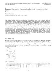
vertical loading and <strong>of</strong>ten trigger <strong>the</strong> liquefaction <strong>of</strong> recently deposited and saturated sandy strata. At this particularsite, soil liquefaction, river scour, and river dredging, may locally affect <strong>the</strong> upper 30 m embeddedlength <strong>of</strong> piles. This soil cannot <strong>the</strong>refore be relied upon to permanently provide full lateral and vertical resistance.Piles consequently had to be proportioned with due regard to <strong>the</strong> effects <strong>of</strong> slenderness, deck displacementand pier fixity.5.2 AppearanceAbove pile level, <strong>the</strong> shape and appearance <strong>of</strong> <strong>the</strong> main piers was determined mainly by structural requirements.At Piers 8, 9 and 10, <strong>the</strong> four inclined circular columns provide a direct transfer <strong>of</strong> load from <strong>the</strong>bridge deck bearings into <strong>the</strong> piles. At Pier 7, where <strong>the</strong>re was insufficient clearance between deck and pilecap to fit columns, a solid plinth had to be used.5.3 Shock Transmission UnitsThe bridge was fitted with shock transmission units (STU) at each main pier to lock <strong>the</strong> deck to <strong>the</strong> substructureunder seismic loading. These permit <strong>the</strong> horizontal seismic inertial forces to be resisted by shear andbending in <strong>the</strong> piles <strong>of</strong> all piers. Combinations and permutations <strong>of</strong> scoured and un-scoured piers and pierspartially founded in liquefied and non-liquefied soil under seismic loading had to be considered to find <strong>the</strong>maximum effect at any location. Using this approach it was identified that, for instance, Pier 7 in its unscouredstate, was much stiffer than <strong>the</strong> adjacent piers when <strong>the</strong>y were scoured, <strong>the</strong>refore attracting substantialseismic loads to it. For this reason Pier 7 piles were more heavily reinforced than those at o<strong>the</strong>r mainpiers.5.4 Computer AnalysisIn order to accurately predict <strong>the</strong> seismic effects, <strong>the</strong> entire structural system, including deck, towers, cables,piers and piles was modelled as a whole using four-dimensional static and dynamic design and analysis s<strong>of</strong>twareRM2006 ® , and a seismic response spectrum analysis carried out. The soil/structure interaction wasmodelled using non-linear lateral and axial soil springs (derived from p-y and t-z curves respectively) attachedto <strong>the</strong> base and along <strong>the</strong> length <strong>of</strong> <strong>the</strong> pile elements.The design <strong>of</strong> <strong>the</strong> main bridge piers was carriedout using envelopes <strong>of</strong> load effects from <strong>the</strong> main bridge computer analysis. The pier tabletops were additionallydesigned for local forces from <strong>the</strong> shock transmission unit anchorage brackets and <strong>the</strong> bridge bearings.Theseismic design was in accordance with <strong>the</strong> provisions <strong>of</strong> AASHTO LRFD (2004) allowing for development<strong>of</strong> plastic hinging in some members.6 EXTRADOSED BRIDGE AND CABLE DESIGN6.1 General DescriptionExtradosed bridge decks gain <strong>the</strong>ir distinctive character and appearance from <strong>the</strong> use <strong>of</strong> a stay cable supportmember with height (above deck level) <strong>of</strong> between 8 % and 12 % <strong>of</strong> <strong>the</strong> deck span length (e.g. Kasuga 2006).Using this approach, <strong>the</strong> tower tops <strong>of</strong> <strong>the</strong> bridge were set at 25 m above deck level to obtain <strong>the</strong> maximumbenefit from <strong>the</strong> stay cables whilst keeping <strong>the</strong> towers within reasonable slenderness limits. The stay cablesare continuous between deck anchorages, which are located at distances <strong>of</strong> between 36 m and 76 m from <strong>the</strong>piers (Fig. 4). The steel deviator saddles in <strong>the</strong> towers (through which <strong>the</strong> cables pass) are located at heights<strong>of</strong> between 19 m and 24 m above deck level.Figure 4.Layout <strong>of</strong> Stay Cables261
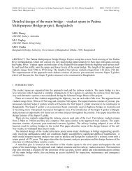
6.2 Allowable Stress in Stay CablesAASHTO LRFD (2004) covers some aspects <strong>of</strong> stay cable design such as wind/vibration, catenary behaviour,and cable removal/replacement, but it does not deal with <strong>the</strong> limitations on permissible stresses in extradosedbridge cables.In a conventional cable-stayed bridge, <strong>the</strong> cable support system is stiffer than <strong>the</strong> deck supportsystem <strong>the</strong>refore a greater proportion <strong>of</strong> vertical live load is carried by <strong>the</strong> cables compared with an extradosedbridge design. Because <strong>of</strong> <strong>the</strong>ir greater unsupported length, cables are also generally subjected to a largerfluctuation <strong>of</strong> stress due to wind. Due to <strong>the</strong>ir exposure to fatigue loading, <strong>the</strong> stresses in <strong>the</strong> stays <strong>of</strong> a cable-stayedbridge are usually limited to approximately 45 % <strong>of</strong> <strong>the</strong> <strong>the</strong>oretical breaking strength (e.g. BS EN1993-1-11 2006). However for extradosed bridges, some designers permit use <strong>of</strong> higher stresses in recognition<strong>of</strong> <strong>the</strong> less onerous fatigue loading (Kasuga 2006).For <strong>the</strong> <strong>Third</strong><strong>Karnaphuli</strong><strong>Bridge</strong>, <strong>the</strong> stay cables werejacked at <strong>the</strong> time <strong>of</strong> installation to 45 % <strong>of</strong> breaking strength. At <strong>the</strong> end <strong>of</strong> construction <strong>the</strong> maximum stressin <strong>the</strong> stay cables, due to force redistribution effects, varied between 42 % and 63 % <strong>of</strong> breaking strength dependingon <strong>the</strong> location. The calculated stress variation in <strong>the</strong> cables due to live load and wind fluctuationswas 25 MPa. The stay cable system was fatigue tested using <strong>the</strong> acceptance test <strong>of</strong> <strong>the</strong> Post-Tensioning Institute(1998). This demonstrated that <strong>the</strong>re were no wire breakages after two million cycles <strong>of</strong> 159 MPa, correspondingto a range <strong>of</strong> between 35 % and 45 % <strong>of</strong> breaking strength. These test results were extrapolated forhigher stresses using <strong>the</strong> Goodman relationship which proved that <strong>the</strong> cables could sustain up to 100 MPastress range at 60 % <strong>of</strong> breaking strength.6.3 Cable forcesUnlike cable-stayed bridge decks, extradosed decks do not require cable “tuning” at <strong>the</strong> end <strong>of</strong> constructionwhen forces are adjusted to match <strong>the</strong> pre-determined values assumed in design. In extradosed decks <strong>the</strong> finalcable forces are dependent on various factors including <strong>the</strong> accuracy <strong>of</strong> <strong>the</strong> initial stressing operations, variationin <strong>the</strong> deck/cable stiffness ratio and <strong>the</strong> actual weight <strong>of</strong> <strong>the</strong> deck. These changes and uncertainties in <strong>the</strong>cable force during construction had to be taken into account in <strong>the</strong> design by use <strong>of</strong> partial load factors.6.4 DurabilityThe stay cables were designed to be robust and durable in order to minimise maintenance. For this reason, <strong>the</strong>strands were individually galvanised, greased and shea<strong>the</strong>d for corrosion protection. In order to facilitate possiblecable replacement, <strong>the</strong> cable system was designed to permit re-stressing from within <strong>the</strong> deck void, andcomplete replacement (during <strong>the</strong> lifetime <strong>of</strong> <strong>the</strong> bridge) <strong>of</strong> <strong>the</strong> whole cable or individual strands.7 SUPERSTRUCTURE DESIGN7.1 <strong>Design</strong> principlesThe main bridge consists <strong>of</strong> a prestressed concrete box girder deck supported by four vertical load bearings ateach <strong>of</strong> <strong>the</strong> main piers (Fig. 5). This configuration allows some deck moment to be carried over into <strong>the</strong> substructureunder unequal span live loading <strong>the</strong>reby reducing <strong>the</strong> midspan moment variation. Pier 6 and <strong>the</strong>south abutment, which are at <strong>the</strong> two ends <strong>of</strong> <strong>the</strong> main bridge, are provided with two bearings each. The deckis prestressed longitudinally by internal bonded prestressing tendons, ei<strong>the</strong>r twenty-seven 15.7 mm diameterstrands or twelve 15.7 mm diameter strands, passing through <strong>the</strong> top and bottom slabs. Additional support isprovided by six stay cables, comprising ninety-one 15.7 mm diameter strands, passing over reinforced concretetowers which are integral with <strong>the</strong> deck. The stay cables, which are anchored at <strong>the</strong> centreline <strong>of</strong> <strong>the</strong>deck, act like external prestressing enhancing <strong>the</strong> vertical shear capacity close to <strong>the</strong> piers and resisting deckflexure.7.2 Tower SaddlesMulti-pipe steel deviator saddles are used in <strong>the</strong> tower tops. This type <strong>of</strong> saddle was preferred to a single pipedeviator tube as it provides a better distribution <strong>of</strong> stress into <strong>the</strong> towers and facilitates <strong>the</strong> replacement <strong>of</strong> individualstrands if needed. A fixed “blocking” system was used to prevent slippage at <strong>the</strong> saddle due to unequalforces in <strong>the</strong> stay cables under live loading. Dampers are provided at cable anchorages to minimise fatigueeffects due to wind vibration.262
Figure 5.Deck Section At Pier7.3 Deck Cross SectionThe deck is braced against transverse distortion by diagonal reinforced concrete struts (Fig. 6). These providea “load path” to transfer <strong>the</strong> vertical component <strong>of</strong> stay cable forces into <strong>the</strong> main webs and <strong>the</strong>y also reduce<strong>the</strong> effective transverse span <strong>of</strong> <strong>the</strong> top slab for carrying local traffic loading. In <strong>the</strong> stayed deck segments <strong>the</strong>struts are prestressed using fifteen 15.7 mm diameter strands to resist <strong>the</strong> axial tensile force. The top slab istransversely prestressed over <strong>the</strong> stayed deck section using four 15.7 mm diameter strands in flat ducts at 450mm centres. This prestressing is necessary to resist tensile in-plane stresses associated with spread <strong>of</strong> <strong>the</strong> centralstay cable anchorage force outwards to <strong>the</strong> webs.Internal diaphragms are provided in <strong>the</strong> box girder deckat <strong>the</strong> piers (above each pair <strong>of</strong> bearings) and also at <strong>the</strong> end <strong>of</strong> <strong>the</strong> haunched section where <strong>the</strong> bottom compressionflange needs to be stabilised (and <strong>the</strong> compressive stress is at a maximum). At all sections, o<strong>the</strong>r thanthose adjacent to <strong>the</strong> diaphragms, <strong>the</strong> permissible compressive stress in <strong>the</strong> bottom flange had to be reduced totake account <strong>of</strong> <strong>the</strong> flange slenderness.Figure 6.Deck Cross Section at Midspan7.4 Computer modellingThe global design <strong>of</strong> <strong>the</strong> main bridge deck was required to comply with AASHTO LRFD (2004). This standardindicates that at ServiceLimitState, fibre stresses shall remain within permissible limits and atStrengthLimitState <strong>the</strong> sections shall have adequate shear, torsional and flexural strength. These design re-263
quirements were automatically verified using s<strong>of</strong>tware RM2006 ® . However local elements, such as <strong>the</strong>prestressing and <strong>the</strong> stay cable anchorages, required specific design procedures.Every stage <strong>of</strong> construction(e.g. traveller movement, segment casting, stressing etc.) was modelled, including <strong>the</strong> effects <strong>of</strong> creep andshrinkage, to provide an envelope <strong>of</strong> design load effects. Since single-stage stressing was specified for <strong>the</strong>stay cables, <strong>the</strong> deck pr<strong>of</strong>ile at each stage <strong>of</strong> segment casting needed to be accurately predicted from <strong>the</strong> timedependentanalysis. This was required to ensure that <strong>the</strong> final stresses in <strong>the</strong> stay cables and deck remainedwithin permissible limits as <strong>the</strong> deck pr<strong>of</strong>ile changed during later phases <strong>of</strong> construction.Three types <strong>of</strong> transversesections were considered in <strong>the</strong> design: pier and abutment diaphragms at bearings, non-stayed deck sections,and stayed deck sections. The design <strong>of</strong> diaphragms was by use <strong>of</strong> “strut and tie” idealisations and conventionalshear/torsion codified design methods. The pier diaphragms were particularly complex (Fig. 7)since tower forces were transferred into <strong>the</strong> bearings through large transfer beams which connect to <strong>the</strong> verticaldiaphragm walls. Finite element modelling was carried out to understand <strong>the</strong> flow <strong>of</strong> forces.The transversedeck sections were modelled in three dimensions using engineering analysis s<strong>of</strong>tware for bridges LUSAS ® tocheck <strong>the</strong> effects <strong>of</strong> <strong>the</strong> cantilever construction sequence, particularly with regard to strut construction and“locked-in” effects.Figure 7.Pier Diaphragm Detail8 CONCLUSION<strong>Design</strong> and construction <strong>of</strong> <strong>the</strong> <strong>Third</strong> <strong>Karnaphuli</strong> <strong>Bridge</strong> has been completed on time and on budget as a result<strong>of</strong> <strong>the</strong> excellent cooperation between <strong>the</strong> Contractor, <strong>Design</strong>er, independent <strong>Design</strong> Checker, Client and <strong>the</strong>Supervision Consultants.Progress to successful completion <strong>of</strong> this <strong>Design</strong> and Build project has benefitedfrom having a viable tender design concept which has changed very little during construction. The considerableinvestment made by <strong>the</strong> Contractor in additional ground investigations and pile testing has enabled <strong>the</strong>development <strong>of</strong> a safe and efficient substructure design.The concrete extradosed design has been shown to bean economical solution for bridging <strong>the</strong> <strong>Karnaphuli</strong>river.ACKNOWLEDGEMENTSThe author would like to acknowledge <strong>the</strong> co-operation and assistance <strong>of</strong> Project Directors and Project Managers<strong>of</strong> RHD, Mr Takayoshi Ono team leader <strong>of</strong> <strong>the</strong> Supervision Consultant, Mr I.A. Khan from HPR DhakaOffice, Mr A. Farooq and Mr K.J. Taylor from HPR London Office, Mr Huangzhijin Deputy GM <strong>of</strong> MBEC,Mr Yu Benjun and Mr Yu Zhengquan from MBEC Site Team, Mr Amin Ahmed from ACL, and many colleaguesat MBEC-ACL-COPRI JV and HPR Ltd.264
REFERENCESAmerican Association <strong>of</strong> State Highway and Transportation Officials.LRFD <strong>Bridge</strong> <strong>Design</strong> Specifications, 3 rd edn. AASHTOWashington, DC, 2004.American Society for Testing and Materials.Standard Test Method for Length Change <strong>of</strong> Hydraulic-Cement Mortars Exposed to aSulphate Solution. ASTM, West Conshohocken, PA, 2004, C1012–04.Housing and Building Research Institute and <strong>Bangladesh</strong> Standards and Testing Institution.<strong>Bangladesh</strong> National Building Code.HBRI & BSTI, Dhaka,1993.British Standards Institution.Steel, Concrete and Composite <strong>Bridge</strong>s, Part 4-Code <strong>of</strong> Practice for <strong>Design</strong> <strong>of</strong> Concrete <strong>Bridge</strong>s. BSI,Milton Keynes, 1990, BS 5400.Castelli, R.J. & Wilkins, E. (2004). Osterberg load cell test results on base grouted bored piles in <strong>Bangladesh</strong>. American Society <strong>of</strong>Civil Engineers, Reston, VA.Geotechnical Special Publication, 124, 587-602,British Standards Institution.Eurocode 3: <strong>Design</strong> <strong>of</strong> Steel Structure-Part 1-11: <strong>Design</strong> <strong>of</strong> Structures with Tension Components. BSI,Milton Keynes, 1993, BS EN 1993-1-11.Farooq, A. & Barr J. Large Diameter Piling-Jamuna <strong>Bridge</strong>.Proceedings <strong>of</strong> <strong>the</strong> International Conference on Current and FutureTrends in <strong>Bridge</strong> <strong>Design</strong>, Construction and Maintenance, Singapore (Frangopol and Das Ed.). Thomas Telford, London, 1999.Kasuga, A. (2006). Extradosed <strong>Bridge</strong>s in Japan.Structural Concrete, 7(3), 91-103.Khan.F.H. Geology <strong>of</strong> <strong>Bangladesh</strong>.The University Press, 1991.Post-Tensioning Institute.Acceptance standards for post-tensioning systems, 1 st edn. PTI, Farmington Hills, MI, 2001.Reimann, K.-U.Geology <strong>of</strong> <strong>Bangladesh</strong>.GebrüderBorntraeger, Berlin-Stuttgart, 1993.265