Mobile Planer Stand Plan - Woodsmith Shop
Mobile Planer Stand Plan - Woodsmith Shop
Mobile Planer Stand Plan - Woodsmith Shop
- No tags were found...
Create successful ePaper yourself
Turn your PDF publications into a flip-book with our unique Google optimized e-Paper software.
MOBILEPLANERSTAND© 2007 August Home Publishing Co.
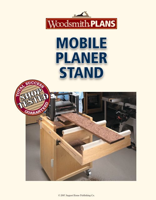
WeekendProject<strong>Mobile</strong> <strong><strong>Plan</strong>er</strong> <strong>Stand</strong>Make your shop workhorse even more productive with this handy project.Pound for pound, a portable planerhas to be one of the hardest-workingmachines in the shop. And whenyou combine your planer with theversatile stand shown above, foryou, the work will get a lot easier.This project starts with a rugged,plywood case that puts the planerat just the right working height.A drawer for accessories, a largeopen storage area, and a set oflocking casters round out the case.But the feature that really standsout is the built-in, adjustable outfeedsupport. The key is that it’sonly “out” when you need it. Whenthe job is complete, the supportswings up over the stand and locksin place for easy movement andcompact storage (inset photo).1 www.<strong>Woodsmith</strong>.com © 2007 August Home Publishing Co. All Rights Reserved.
A Sturdy Plywood CaseEven a portable planer is a fairlyheavy tool and the stand that it sitson may take a considerable amountof abuse. So I wanted to get off onthe right foot by building a verysturdy case. I accomplished thiswith a combination of solid joineryand some “structural” reinforcementin a few critical spots.Sides and Dividers. A look at Figure1 shows you how the plywood caseis put together. The top, bottom,and dividers are joined to the sideswith a tongue and dado, as shownin Figure 1a. This joint gives youboth good gluing strength andracking resistance.The first step is to cut the twocase sides to size. Next, each sideneeds four dadoes. Your only worryhere is to match the position of thedadoes on both side pieces.With the work on the sides complete,you can cut the top, bottom,and two dividers to size. The topand upper divider are identical.The bottom and lower divider arelikewise identical, but 3 ⁄ 4 " narrower(front to back). This makes roomfor a plywood back panel you’lladd later. After cutting snug-fittingtongues on the dividers, you canstart assembling the case. Glueand clamps are all it takes.Reinforcement. Next, I turned myattention to beefing up the casein a few spots. First, I added thePass-throughshelf for moreefficient work andextra storageShallow drawerprovides easyaccess toaccessoriesLarge, versatile openstorage area3 ⁄ 4 " plywood back panel (Figure1b). This adds an extra level ofracking resistance and also closesin the drawer opening and lowerstorage area. The back is sized tofit between the sides. It butts upto the upper divider and sits flushwith the case bottom (Figure 1b).Next, I strengthened the jointsbetween the top and the sides bygluing a second layer of plywood1 2b.a.3 www.<strong>Woodsmith</strong>.com © 2007 August Home Publishing Co. All Rights Reserved.
34a.a.b.to the inside of the case, as shownin Figure 2. You’ll find a handyclamping tip that will help you withthis in the box below.The final spot for reinforcement isthe bottom of the case. Here again, I“doubled up” the plywood to createa very solid foundation for the casters(Figure 2). And I should notethat this piece extends flush to thecase back and sides.With the stiles in place you canstart adding the horizontal edging.These pieces are thinner — just1 ⁄ 2 " thick — and are simply cut tofit between the stiles. And here iswhere there’s a minor differencebetween the front and back.On the front of the case, all ofthese pieces are sized to fit flushwith the surfaces of the plywood(a double thickness at the bottom).At the back, there are only threehorizontal edging pieces. The twolower pieces are sized to concealthe joint between the dividers andthe case back (Figure 4a).The Casters. Once all the edgingwas in place, I took the time to addthe locking casters. This way, youcan easily move the case while finishingthe job. Just flip the case overand screw them to the bottom.the edgingAt this point, you have a solid case,but it’s a little unfinished on theoutside. Some hardwood edgingglued to the plywood case will giveit a cleaner look and help it standup to shop wear and tear.A look at Figures 3 and 4 aboveshows what needs to be done. Theedging I applied is a cross betweensimple edging and a face frame. Thepieces are simply glued in place oneat a time. The front and back of thecase get a similar treatment, butthe pieces are a bit different.The Pieces. The first step is to glue a“cap” on the top edges of the sidesand trim it flush. Next, I added side“stiles” cut from 3 ⁄ 4 "-thick stock.They should be flush at the top,bottom, and outside edges, as inFigures 3a and 3b.The challenge I came up againstwhen assembling the case washow to apply clamping pressurein places my clamps couldn’treach. Here are a couple of tricksI used to get the job done.When gluing the filler panelsinto the case, I used heavy caulswith a slight bow planed onone edge. A clamp tightenedat either end is all you need toapply pressure across the widthof the panels (upper drawing).The lower drawing showshow I teamed up heavy rubberbands and spring clamps toglue edging in place. Simplystretch the rubber band andpinch it with the clamp.clamping tips4 www.<strong>Woodsmith</strong>.com © 2007 August Home Publishing Co. All Rights Reserved.
Adding a DrawerThere are a few items that you’llwant to keep close by your planer— spare knives, set-up gauges, theowner’s manual, and various adjustmenttools. The shallow drawer inthe center of the case is the perfectspot for these things.Construction Basics. As you seein the drawing at right, I kept thedrawer simple. It’s sized to fit theopening in the case with 1 ⁄ 16 " clearanceon either side. And I leftenough top-to-bottom clearance toaccommodate the “top-mounted”pull. The drawer slides on thelower divider, and a pair of guideskeep it centered (Figure 5c).The joinery is basic, but solid.The ends of the front and backare rabbeted to accept the sides.A groove in all four parts will holdthe plywood bottom. Then you canglue everything together.A Low-Profile Pull. Once the draweris assembled, you can add its oneunique feature — the pull. I wanteda drawer pull that would be easy toget a hold of, but also out of “harm’sway.” A length of aluminum anglewas the answer. As you can seein Figure 5d, the combination ofa groove cut into the drawer front5a. b.and the overhanging flange of theangle makes an easy-to-grip, lowprofilepull. The box below showsyou how to make and fit the pull tothe drawer front.c. d.Drawer Guides. Now the drawerguides can be cut to size and gluedin place. They should stick past theinside edges of the stiles a bit to keepthe drawer centered in the opening.making a drawer pullCreating the handy, low-profile pullfrom a length of aluminum angle isa pretty straightforward, three-stepjob. The drawings here take youthrough the process.The first step is to create ashallow finger recess in the drawerfront by cutting a wide groovealong its length (detail ‘a’). I useda dado blade on the table saw, andsome sanding, to get this job done.Next, I switched to a standardblade and tilted it to 45° to bevelone edge of the groove (detail ‘b’).Now, the aluminum angle canbe cut to length and countersunkscrew holes can be drilled in oneflange (left drawing). Finally, youcan screw the pull to the top of thedrawer front with the upper flangeflush to the inside edge.a.b.{ Low-Profile. A lengthof aluminum anglemakes an easy-to-grip,low-profile drawer pull.5 www.<strong>Woodsmith</strong>.com © 2007 August Home Publishing Co. All Rights Reserved.
Building theOutfeed SupportWith the case complete, thenext step is to start work onthe pivoting, adjustable outfeedsupport.Overview. First, let’s take alook at the overall assembly.The outfeed support startswith two long arms thatpivot on bolts fastened atthe back edge of the case.The arms carry two supporta.assemblies — one fixed atthe end of the arms for longstock and a second, adjustablesupport for shorterpieces. Two different setsof stops hold the assemblyin either the horizontal orthe vertical position.Support Arms. Start bymaking and installing thesupport arms and the stops(Figure 6). Then on the followingpages you’ll see how the two supportsare built and installed.First, I cut the two arms tosize from 3 ⁄ 4 "-thick stock. Then Itook them to the router table androuted a stopped groove partwayalong the inside face of each piece(Figure 6b). This groove will holdthe adjustable support assembly.Next, to accommodate the lockingmechanism of the adjustablea.6support, I routed a 1 ⁄ 4 "-wide slotdown the center of the groove(Figure 6). I just drilled a starterhole at each end of the slot andthen routed between them.As you can see above, the fixedsupport is held in rabbets cut intothe ends of the arms. Cutting theserabbets and drilling pilot holes forthe screws used to attach the armscompletes the work on the “outboard”ends (Figure 6c).b.Handy Features.The adjustablehorizontal stops andthe self-engagingcatch make thestand a lot moreuser friendly.b.The Stops. Before mounting thearms, you’ll want to install bothsets of stops. The vertical stops aresimply sections of aluminum anglescrewed to the back edge of thecase, as shown in Figure 6a.The details for the adjustablehorizontal stop assemblies areshown in the photo and detail ‘a’below. In a nutshell, the head ofa bolt threaded into an insert inthe arm butts up to a piece of aluminumangle screwed to the case.Turning the bolt inor out, adjusts theheight of the supportson the oppositeend of the arms. It’ssimple, but effective.Mount the Arms.With the two stopsinstalled, you can boltthe arms to the case(Fig. 6). And finally, Iwanted to make surethe outfeed supportassembly didn’t fallfrom its upright position when Imoved the stand. A self-engagingflip catch added to one arm ensuresthis doesn’t happen. Figures 6ashows how it works and where toinstall it. Detail ‘b’ at left gives youall the dimensions you need.c.6 www.<strong>Woodsmith</strong>.com © 2007 August Home Publishing Co. All Rights Reserved.
7b.a.With the support arms installed,you can start on the business end ofthe assembly — the two supports.This is pretty straightforward, butone thing needs explanation.Straight and Level. The real key togetting the most from the outfeedsupports is to install them perfectlystraight and levelwith the planerbed. Having solidoutfeed supportat the right height< LockingMechanism.The adjustablesupport is quicklylocked in place bytightening a starknob.gives you two important benefits.First, by supporting a workpieceas it exits the planer, you eliminatea lot of running back and forthfrom the infeed to the outfeedside. Second, it helps prevent theproblem of snipe by supporting theworkpiece perfectly level with theplaner bed through the entire cut.So you want the supports positionedat just the right height, butthe question is, how do you sizethem to achieve this? The easyanswer is to first make the supportsto rough height and then custom fitthem to your planer sitting on thestand. The box at the bottom of thefollowing page shows how to dothis. At this point, to get a ballparkfigure for the supports, you needto set your planer on the stand andbolt it down, as shown above.The Adjustable Support. With thisdone, you can now get to work.The adjustable support is moreinvolved, so I started there.If you take a look at Figures 7and 7b above, you’ll see how theadjustable support is built. It’smade up of three pieces cut from3 ⁄ 4 "-thick hardwood and a cap madefrom a section of PVC pipe.The base of the support is a guidepiece that rides in the grooves inthe support arms. The key hereis to size this piece so that it slideseasily in the grooves.Down the center of the guide,I cut a groove to hold a lengthof threaded rod. The rod (gluedin place with epoxy) will extendthrough the slots in the supportarms. This allows you to tighten astar knob at either end and lock thesupport in position (photo at left).On top of the guide piece, I glueda shorter guide cover. It’s sized tofit between the support arms andits main purpose is to help keep thesupport aligned squarely betweenthe two arms. A look at Figure 7awill give you the idea here.The third piece is an uprightthat’s screwed at right angles tothe guide assembly. For now, youcan cut this piece to length, butleave it extra wide for final fittingand don’t fasten it in place.The Fixed Support. Before you beginworking on the PVC pipe cap for the7 www.<strong>Woodsmith</strong>.com © 2007 August Home Publishing Co. All Rights Reserved.
adjustable support, you’ll need tomake the fixed support upright.It’s simply cut to fit between therabbets in the support arms. Again,you’ll want to cut it extra wide. Butdon’t screw it to the support armsjust yet (Figure 8).A Smooth-Sliding Cap. Now you canmake and add caps to the uprightsin preparation for the final fit andassembly. Here, I wanted thebearing surface of the supports tobe friction-free and “catch-free.”The smooth surface and roundshape of some 1 1 ⁄ 2 " I.D. PVC pipe isthe perfect solution.To fit the caps over the uprights,you’ll need to cut an accuratelysized slot down the length of eachpipe section. The key here is tosize the slot so that the cap snuglypinches the upright and stays put,as in Figures 7b and 8.A Custom Fit. With caps added tothe two uprights, the final step is to8custom fit and install the supportson the support assembly. The techniqueI used to get them perfectlyaligned with the planer bed isshown in box below.a.And once the two uprights arescrewed in place, you’re in business.All you need to do now iscome up with a project to put yourhard-working planer to use.aligning the supportsInstalling the two supports sothat they were perfectly alignedwith the bed of the planer turnedout to be a lot easier than Ithought. As I mentioned before,the trick is to cut the piecesextra wide and then custom fitthem to the support assemblyusing the planer bed for reference.The drawings show thesimple steps involved.The first step, shown inFigure 1, is to “zero out” the twosupport arms by aligning themparallel to top of the stand (andplaner bed).Now, you can align the adjustablesupport to the planer bedwith the help of a pair of straightedgedblanks (Figure 2). Aftermarking and trimming the wastefrom the upright, clamp it backin place and install the screws.Then reposition the blanks andfollow the same procedure forthe fixed support (Figure 3).12 38 www.<strong>Woodsmith</strong>.com © 2007 August Home Publishing Co. All Rights Reserved.


