PowerLogic ION7550 / ION7650 User Guide - Schneider Electric
PowerLogic ION7550 / ION7650 User Guide - Schneider Electric
PowerLogic ION7550 / ION7650 User Guide - Schneider Electric

Create successful ePaper yourself
Turn your PDF publications into a flip-book with our unique Google optimized e-Paper software.
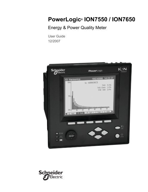
<strong>PowerLogic</strong> ® <strong>ION7550</strong> / <strong>ION7650</strong>Energy & Power Quality Meter<strong>User</strong> <strong>Guide</strong>12/2007
NoticesDangerCautionThis symbol indicates the presence of dangerous voltage within andoutside the product enclosure that may constitute a risk of electricshock, serious injury or death to persons if proper precautions are notfollowed.This symbol alerts the user to the presence of hazards that may causeminor or moderate injury to persons, damage to property or damageto the device itself, if proper precautions are not followed.NoteThis symbol directs the user’s attention to important installation,operating and maintenance instructions.Installation ConsiderationsInstallation and maintenance of the <strong>ION7550</strong> / <strong>ION7650</strong> meter should only beperformed by qualified, competent personnel that have appropriate training andexperience with high voltage and current devices. The meter must be installed inaccordance with all local and national electrical codes.DANGERFailure to observe the following instructions may result in severe injury or death.During normal operation of the <strong>ION7550</strong> / <strong>ION7650</strong> meter, hazardous voltagesare present on its terminal strips, and throughout the connected potentialtransformer (PT), current transformer (CT), digital (status) input, control powerand external I/O circuits. PT and CT secondary circuits are capable of generatinglethal voltages and currents with their primary circuit energized. Followstandard safety precautions while performing any installation or service work(i.e. removing PT fuses, shorting CT secondaries, etc).The terminal strips on the meter base should not be user‐accessible afterinstallation.Do not use digital output devices for primary protection functions. Theseinclude applications where the devices perform energy limiting functions orprovide protection of people from injury. Do not use the <strong>ION7550</strong> / <strong>ION7650</strong> insituations where failure of the devices can cause injury or death, or causesufficient energy to be released that can start a fire. The meter can be used forsecondary protection functions.Do not HIPOT/Dielectric test the digital (status) inputs, digital outputs, orcommunications terminals. Refer to the label on the <strong>ION7550</strong> / <strong>ION7650</strong> meterfor the maximum voltage level the device can withstand.
CAUTIONObserve the following instructions, or permanent damage to the meter may occur.The <strong>ION7550</strong> / <strong>ION7650</strong> meter offers a range of hardware options that affectinput ratings. The <strong>ION7550</strong> / <strong>ION7650</strong> meter’s serial number label lists allequipped options. Applying current levels incompatible with the current inputswill permanently damage the meter. This document provides installationinstructions applicable to each hardware option.The <strong>ION7550</strong> / <strong>ION7650</strong> meter’s chassis ground must be properly connected tothe switchgear earth ground for the noise and surge protection circuitry tofunction correctly. Failure to do so will void the warranty.Terminal screw torque: Barrier‐type (current, voltage, and relay terminal screws:1.35 Nm (1.00 ft‐lbf) max. Captured‐wire type (digital inputs/outputs,communications, power supply: 0.90 Nm (0.66 ft.lbf) max.FCC NoticeThis equipment has been tested and found to comply with the limits for a Class Adigital device, pursuant to Part 15 of the FCC Rules. These limits are designed toprovide reasonable protection against harmful interference when the equipment isoperated in a commercial environment. This equipment generates, uses, and canradiate radio frequency energy and, if not installed and used in accordance withthe instruction manual, may cause harmful interference to radio communications.Operation of this equipment in a residential area is likely to cause harmfulinterference in which case the user will be required to correct the interference at hisown expense. The Ringer Equivalence Number (REN) for the <strong>ION7550</strong> / <strong>ION7650</strong>optional internal modem is 0.6. Connection to the <strong>ION7550</strong> / <strong>ION7650</strong> internalmodem should be made via an FCC Part 68 compliant telephone cord (notsupplied). The <strong>ION7550</strong> / <strong>ION7650</strong> cannot be used on a public coin phone serviceor party line services.Network Compatibility Notice for the Internal ModemThe internal modem in meters equipped with this option is compatible with thetelephone systems of most countries in the world, with the exception of Australiaand New Zealand. Use in some countries may require modification of the internalmodem’s initialization strings. If problems using the modem on your phonesystem occur, please contact <strong>Schneider</strong> <strong>Electric</strong> Technical SupportStandards ComplianceCSA: Certified to CAN/CSA C22.2 No.1010-1Certified toUL 3111Made by Power Measurement Ltd.
<strong>PowerLogic</strong>, ION, ION Enterprise, MeterM@il, WebMeter and Modbus are eithertrademarks or registered trademarks of <strong>Schneider</strong> <strong>Electric</strong>. All other trademarksare property of their respective owners.Covered by one or more of the following patents:U.S. Patent Noʹs 7010438, 7006934, 6990395, 6988182, 6988025, 6983211, 6961641,6957158, 6944555, 6871150, 6853978, 6825776, 6813571, 6798191, 6798190, 6792364,6792337, 6751562, 6745138, 6737855, 6694270, 6687627, 6671654, 6671635, 6615147,6611922, 6611773, 6563697, 6493644, 6397155, 6236949, 6186842, 6185508, 6000034,5995911, 5828576, 5736847, 5650936, D505087, D459259, D458863, D443541,D439535, D435471, D432934, D429655, D427533.
Table of ContentsChapter 1 Introduction .................................................................. 9Chapter 2 Templates, Frameworks and Firmware ........................ 21Chapter 3 Front Panel ................................................................. 27Chapter 4 Basic Setup ................................................................. 55Chapter 5 Security ...................................................................... 65Chapter 6 Communications ......................................................... 77Chapter 7 Third-party Protocols ................................................... 97Chapter 8 Time ......................................................................... 127Chapter 9 Demand ................................................................... 133Chapter 10 Inputs / Outputs ....................................................... 137Chapter 11 Energy Pulsing .......................................................... 147Chapter 12 Logging and Trending ............................................... 153Chapter 13 Revenue ................................................................... 169Chapter 14 Power Quality .......................................................... 177Chapter 15 Test Mode ................................................................ 187Chapter 16 Meter Resets ............................................................. 191Chapter 17 Alerting .................................................................... 197Chapter 18 Setpoints .................................................................. 203Chapter 19 Reporting ................................................................. 215
1 IntroductionThis manual discusses features of the <strong>PowerLogic</strong> ® <strong>ION7550</strong> and <strong>ION7650</strong> meterand provides configuration instructions. Throughout the manual, the term“meter” refers to both meter models. All differences between the models, such asa feature specific to one model, are indicated with the appropriate model number.NOTEThis user guide also covers the <strong>ION7550</strong> RTU. Differences between the RTU and standard model<strong>ION7550</strong> / <strong>ION7650</strong> meters are detailed in the <strong>PowerLogic</strong> <strong>ION7550</strong> RTU Option document.By the time you are ready to use this guide, your meter should be installed, mostbasic setup should have been performed, and communications/basic operationshould have been verified. If the unit is not yet installed and operational, refer tothe Installation <strong>Guide</strong> shipped with the meter.This chapter provides an overview of <strong>ION7550</strong> and <strong>ION7650</strong> meters, andsummarizes many of their key features.In This Chapter <strong>ION7550</strong> and <strong>ION7650</strong> Meters . . . . . . . . . . . . . . . . . . . . . . . . . . . . . . . . 10The ION Meter in an Enterprise Energy Management System . . . . . . . . . . . . . . 10 Meter Features . . . . . . . . . . . . . . . . . . . . . . . . . . . . . . . . . . . . . . . . . . . . . 12Measured Parameters . . . . . . . . . . . . . . . . . . . . . . . . . . . . . . . . . . . . . . . . . . . . . . . . . 12Localization Options . . . . . . . . . . . . . . . . . . . . . . . . . . . . . . . . . . . . . . . . . . . . . . . . . . 14Data Display and Analysis Tools . . . . . . . . . . . . . . . . . . . . . . . . . . . . . . . . . . . . . . . 14Supported Protocols . . . . . . . . . . . . . . . . . . . . . . . . . . . . . . . . . . . . . . . . . . . . . . . . . . 15Communications Options . . . . . . . . . . . . . . . . . . . . . . . . . . . . . . . . . . . . . . . . . . . . . . 15Digital and Analog I/O Options . . . . . . . . . . . . . . . . . . . . . . . . . . . . . . . . . . . . . . . . . 15ION Enterprise Software Support . . . . . . . . . . . . . . . . . . . . . . . . . . . . . . . . . . . . . . . 16ION Setup Software Support . . . . . . . . . . . . . . . . . . . . . . . . . . . . . . . . . . . . . . . . . . . 18 Getting More Information . . . . . . . . . . . . . . . . . . . . . . . . . . . . . . . . . . . . . 18© 2007 <strong>Schneider</strong> <strong>Electric</strong>. All rights reserved. Page 9
Chapter 1 - Introduction<strong>ION7550</strong> / <strong>ION7650</strong> <strong>User</strong> <strong>Guide</strong><strong>ION7550</strong> and <strong>ION7650</strong> Meters<strong>ION7550</strong> and <strong>ION7650</strong> intelligent metering and control devices provide revenueaccurate,true RMS measurements of voltage, current, power and energy, and arecomplemented by extensive I/O capabilities, comprehensive logging, andadvanced power quality measurement and compliance verification functions. Themeters come with an extensive selection of pre‐configured data screens andmeasurements, so you can use the meters “out of the box” or customize them to fityour unique requirements.<strong>ION7550</strong> and <strong>ION7650</strong> meters can replace numerous transducers, traditionalmeters, and control circuits. You can integrate the meters with ION ® software orother energy management, SCADA, automation and billing systems, usingmultiple industry‐standard communication channels and protocols.Common Meter ApplicationsRevenue meteringSubstation automationPower quality monitoring (with Flicker)Commercial/industrial operations meteringDemand and power factor controlSCADA (supervisory control and data acquisition)Distributed generation (generator) monitoring and controlThe ION Meter in an Enterprise Energy Management SystemYou can use <strong>ION7550</strong> and <strong>ION7650</strong> meters as standalone devices, but theirextensive capabilities are fully realized when used with ION software as part of anenterprise energy management (EEM) system.EEM systems give energy suppliers, service providers, and large industrial andcommercial energy consumers the tools to meet all the challenges andopportunities of the new energy environment. EEM systems use real‐timeinformation and control to directly address a broad range of requirementsthroughout the power delivery chain and across an entire enterprise. Thesesystems offer an integrated solution to managing new billing structures,distributed generation, energy purchasing, energy cost control, operationalefficiency, and power quality and reliability.Applications that include the meter typically require additional equipment.Display and analysis software tools are almost always used to manage, interpretand distribute the data measured or logged by a meter. There are usually a varietyof tools used, and often these tools are connected using different communicationsstandards and protocols. In many cases, a meter must also provide controlcapabilities and device‐level data sharing.Page 10© 2007 <strong>Schneider</strong> <strong>Electric</strong>. All rights reserved.
<strong>ION7550</strong> / <strong>ION7650</strong> <strong>User</strong> <strong>Guide</strong>Chapter 1 - IntroductionThe meter can adapt to many situations. Advanced communications allow data tobe shared simultaneously across multiple networks, built‐in I/O providesmonitoring and control capabilities, and a variety of display and analysis toolsmonitor your power system.Internet Connectivity- MeterM@il- WebMeter functionality- XML compatibilityPower System ConnectionsPhase voltage, phase current, ground current,and neutral current from Wye, Delta, or singlephasepower systemsData Analysis Tools- Power Monitoring Network- Third-Party Software forModbus, DNP 3.00, Mv90Corporate NetworkOnboard I/O- Pulses- Breaker Status- Control Signals- Energy PulsesOn-Site Data Display- 320 by 240 pixel LCDRemote Data Display- Vista screens- WebReach screens- WebMeter screensCommunications- RS-232 and high speed RS-485- Internal Modem- Front ANSI optical port- 10Base-T, 100Base-T and 100Base-FX (fiber)Ethernet- Interoperability- Protocols: ION, Modbus Master, Modbus RTU,Modbus TCP, DNP 3.00, ModemGate (modemto RS-485 gateway), EtherGate (Ethernet to RS-485 gateway), GPS: Arbiter, GPS: True Time/Datum, SNMP© 2007 <strong>Schneider</strong> <strong>Electric</strong>. All rights reserved. Page 11
Chapter 1 - Introduction<strong>ION7550</strong> / <strong>ION7650</strong> <strong>User</strong> <strong>Guide</strong>Meter FeaturesYour meter includes an impressive array of standard features. The following is anoverview of those features.Measured Parameters<strong>ION7550</strong> / <strong>ION7650</strong> meters provide fully bi‐directional, 4‐quadrant, revenueaccurateor revenue‐certified energy metering. The following is a selection of someparameters measured by these meters.EnergyThe meters provide all common active, reactive and apparent energy parameters.kWh delivered and receivedkWh, kVARh, kVAh net (delivered ‐ received)kWh, kVARh, kVAh total (delivered + received)kVARh, kVAh delivered and receivedVolt‐hours and amp‐hoursIntegration of any instantaneous measurementEnergy registers can be logged automatically on a programmed schedule.All energy parameters represent the total for all three phases. Energy readings aretrue RMS. Maximum range of energy readings is 999,999,999. Beyond this value,readings roll over to zero (0).DemandThe meters support standard demand calculation methods, including block,rolling block, and predicted demand. They can measure demand on anyinstantaneous value and record peak (maximum) and minimum demand withdate and time‐stamps to the second. Peak demand registers can be reset manually(password protected) or logged and reset automatically on a programmedschedule. Measurements include:kW, kVAR, kVA demand, min/maxAmps, Volts demand, min/maxDemand on any instantaneous measurementInstantaneousBoth meters provide a choice of high accuracy, 1 second or high‐speed, 1/2 cyclemeasurements, including true RMS, per phase and total for:Voltage and current Active power (kW) and reactive power (kVAR)Page 12© 2007 <strong>Schneider</strong> <strong>Electric</strong>. All rights reserved.
<strong>ION7550</strong> / <strong>ION7650</strong> <strong>User</strong> <strong>Guide</strong>Chapter 1 - IntroductionApparent power (kVA)Power factor and frequencyVoltage and current unbalancePhase reversalHarmonicsComplete harmonic distortion metering, recording and real‐time reporting, up tothe 63rd harmonic (511th for <strong>ION7650</strong> via ION Enterprise software) for all voltageand current inputs.Individual harmonics (including magnitude, phase and inter‐harmonics for the<strong>ION7650</strong>)Total even harmonics and total odd harmonicsTotal harmonics (even + odd)K‐factor, Crest factorMin/Max RecordingThe meters record each new minimum and new maximum value with date andtime‐stamp for the following parameters:Voltage and current min/maxkW, kVAR, and kVA min/maxPower factorFrequencyVoltage unbalancePlus any measured valuePower QualityThe meters measure and record the following parameters:Sag/SwellsTransients (<strong>ION7650</strong> only)<strong>ION7650</strong> meters comply with the following power quality standards:EN50160 including Flicker (with ordering option only) IEC 61000‐4‐30The meters also have the following power quality related features:Disturbance Direction Detection: This allows the meter to analyze disturbanceinformation and determine the direction of the disturbance, relative to the meter,with an accompanying degree of confidence. When used in conjunction withother meters with the feature, this enables you to determine the source of adisturbance more quickly and accurately, prevent repeat occurrences andminimize facility downtime.© 2007 <strong>Schneider</strong> <strong>Electric</strong>. All rights reserved. Page 13
Chapter 1 - Introduction<strong>ION7550</strong> / <strong>ION7650</strong> <strong>User</strong> <strong>Guide</strong>Setpoint Learning: This allows you to configure your meter to learn certaindisturbance‐related values, such as what constitutes a sag, swell, transient, orhigh or low setpoint.Localization OptionsThe meter can be customized to use different regional settings, including: the language used for the display the currency symbols used time, date and digit formats IEC/IEEE symbols and calculationsData Display and Analysis ToolsDisplay and analyze meter data with a wide variety of tools.The Front PanelUse the meter’s front panel interface for local monitoring and standaloneapplications. The bright LCD display lets you view real‐time values and performbasic device configuration. The front panel is often used in combination with anION software system, providing an interface for field personnel.NOTETRAN (transducer) model meters do not have a front panel.WebMeter ® Embedded Web Server FeatureEthernet meters include WebMeter functionality, an on‐board web server thatprovides quick and easy access to real‐time energy, basic power quality andtrending and forecasting information without special software. The built‐in webpages display a range of energy and basic power quality information through theweb‐enabled device. These pages also support basic meter configuration tasks.MeterM@il ® Internal E-Mail Client FeatureConfigure the meter to automatically email high‐priority alarm notifications orscheduled system‐status update messages to anyone, anywhere within the facilityor around the world. Specify the type of event that triggers an email alert, such aspower quality disturbances or logged data at any pre‐determined interval, andhave your ION software administrator program the meter to respond with aMeterM@il message when these events occur. MeterM@il messages are receivedlike any email message over a workstation, cell phone, pager, or PDA.Page 14© 2007 <strong>Schneider</strong> <strong>Electric</strong>. All rights reserved.
<strong>ION7550</strong> / <strong>ION7650</strong> <strong>User</strong> <strong>Guide</strong>Chapter 1 - IntroductionSupported ProtocolsXML CompatibilityYour meter can exchange information using industry‐standard XML format. Thissimple machine‐readable format supports easy integration with custom reporting,spreadsheet, database, and other applications.You can integrate the meter into various industry‐standard networks. Data thatthe meter measures can be made available to other devices using Modbus RTU,Modbus/TCP, DNP 3.0 and SNMP protocols, as well the MV‐90 translation system.You can also configure the meter to import data from other devices on thesenetworks. With these advanced communications functions, the power of the metercan be utilized in most existing power monitoring systems. Any data display andanalysis software that works with Modbus RTU or DNP 3.0 devices also functionswith the meter.Communications OptionsThe standard meter includes a selectable RS‐232/RS‐485 port (the factory default isRS‐232), a high‐speed RS‐485 port, and an ANSI Type II front optical port forcommunications in the field. Ordering options include 10Base‐T, 100Base‐T and100BFX (fiber) Ethernet ports and a 56 kbps internal modem (both FCC and CTR‐21 compliant). Depending on the hardware options purchased, up to five separateports can communicate simultaneously.NOTEThe communications card is retrofittable – it can be replaced while the meter is in the field.Digital and Analog I/O OptionsThe meter’s digital inputs and outputs connect to the captured‐wire terminals nearthe base of the unit. Additionally, an LED on the front panel is configured forenergy pulsing. You can also order an optional analog I/O card with your meter.NOTEThe I/O card is retrofittable – it can be replaced while the meter is in the field.Digital InputsThe meter contains eight self‐excited digital inputs capable of detecting a pulserate of 20 pulses/second and timestamping transitions with 1ms resolution. Theycan be used for monitoring external contacts or pulse counting applications. Theseinputs use a current sensing technique to monitor contact status by providing aninternal 30 VDC supply for self‐excitation.© 2007 <strong>Schneider</strong> <strong>Electric</strong>. All rights reserved. Page 15
Chapter 1 - Introduction<strong>ION7550</strong> / <strong>ION7650</strong> <strong>User</strong> <strong>Guide</strong>Relay OutputsThe meter contains four solid‐state Form A outputs and three mechanical Form Crelays. The solid‐state outputs have a maximum voltage rating of 30 VDC andmaximum current rating of 100 mA. The mechanical relays are rated at 250 VAC /30 VDC and can switch up to 10 A loads.Analog Inputs and Analog OutputsThe meter offers an optional Analog I/O expansion card with numerous options:four 0 to 1 mA analog inputsfour 0 to 20 mA analog inputsfour ‐1 to 1 mA analog outputsfour 0 to 20 mA analog outputsfour 0 to 20 mA analog inputs & four 0 to 20 mA outputsfour 0 to 1 analog inputs and four ‐1 to 1 mA analog outputsNOTEAll options have an additional eight digital inputs on the card.ION Enterprise Software SupportThe complete ION Enterprise software package integrates the meter into a fullynetworked information system with other meters and local and wide‐areacomputer networks. ION Enterprise is recommended for all power monitoringsystems where advanced analysis and control capabilities are required.ION Enterprise provides tools for managing your power monitoring network,logging data, analyzing real‐time and logged data, generating power systemreports, and creating custom functionality at the meter level.VistaVista presents a graphical view of your power system, allowing you to view andanalyze real‐time data from power meters and historical data from the IONdatabase. Vista reports on the status of your system components, informing you ofalarm conditions and providing you with control capabilities for initiatingintelligent device functions or actuating field machinery. Vista includessophisticated tools for analyzing real‐time and logged power data and systemevents.For more information, refer to the Vista section in the online ION Enterprise Help.Page 16© 2007 <strong>Schneider</strong> <strong>Electric</strong>. All rights reserved.
<strong>ION7550</strong> / <strong>ION7650</strong> <strong>User</strong> <strong>Guide</strong>Chapter 1 - IntroductionWebReachThe WebReach component of ION Enterprise adds thin‐client supportfunctionality to the ION Enterprise software. With the WebReach feature you canuse the web browser from any machine on your network to view the Vistadiagrams of all the meters on your network, regardless of whether they are locatedlocally or across the country. You can create custom screens in Vista for display inyour web browser, including real‐time numeric data, background graphics ordiagrams, and basic views of event, data and waveform logs.ReporterReporter lets you define and create comprehensive database reports usingMicrosoft Excel. Configured Power Quality, Load Profile, Energy and Demand,EN50160, and IEC61000‐4‐30 reports are included with Reporter.For more information, refer to the Reporter section in the onlineION Enterprise Help.Management ConsoleManagement Console is used to build your ION Enterprise power‐monitoringnetwork to reflect the way the physical communications network is wired, so IONEnterprise software can communicate with your devices. The network is createdusing sites, servers, modems, and intelligent devices that can be added, removed,configured, or duplicated.You can access the following tools from the Management Console menus:Diagnostics Viewer is the primary source of troubleshooting information inION Enterprise.Device Upgrader lets you upgrade the operating software inside an ION meter.Remote Modem Setup lets you set up modems for remote sites.Database Manager lets you manage your ION Enterprise databases with bothmanual tasks and scheduled tasks.<strong>User</strong> Manager lets you configure ION Enterprise software user accounts thatdefine different operations permitted within the ION software, such as viewingmeter data, performing control actions, or configuring the meters.License Manager lets you upgrade the number of devices you can have withoutre‐installing the software.Modbus Device Importer lets ION Enterprise software recognize and integratethird‐party Modbus devices more readily.For more information, refer to the Management Console section in the onlineION Enterprise Help.© 2007 <strong>Schneider</strong> <strong>Electric</strong>. All rights reserved. Page 17
Chapter 1 - Introduction<strong>ION7550</strong> / <strong>ION7650</strong> <strong>User</strong> <strong>Guide</strong>DesignerDesigner lets you customize the operation of hardware nodes, such as ION meters,and software nodes, such as the Virtual Processor, the Log Inserter, and the QueryServer. Designer uses a WYSIWYG graphical user interface to pictorially representa node’s configuration (i.e., how the different ION modules are linked together ina framework). In addition to giving you the ability to change the settings of anyION module, Designer also lets you change existing links between modules, addnew links, add new modules or delete modules. Designer helps you visualize thelogic when you are programming custom functionality in an ION device.For more information, refer to the Designer section in the onlineION Enterprise Help.ION Setup Software SupportION Setup is a software tool designed specifically to configure and test meters.ION Setup offers an intuitive graphical interface for performing basic meter setup,installing templates into meters, viewing real‐time and reset accumulated values,verifying meter calibration and measurements, and setting up advanced security.Getting More InformationAdditional information is available from <strong>Schneider</strong> <strong>Electric</strong>:visit our web site at www.powerlogic.comcontact your local <strong>Schneider</strong> <strong>Electric</strong> representativecontact <strong>Schneider</strong> <strong>Electric</strong> directlyDocuments that are related to the installation, operation and application of themeter are as follows:<strong>ION7550</strong> / <strong>ION7650</strong> Installation <strong>Guide</strong>This brief manual is shipped with each meter. It details the mounting, wiring andbasic setup of the device.ION ReferenceThe ION Reference describes ION architecture (the common software architecturein all ION devices) and provides an explanation for each of the ION modules.Online ION Enterprise Help & Online ION Setup HelpIn‐depth online help systems for ION Enterprise and ION Setup software.Technical NotesTechnical notes provide instructions for using meter features and for creatingcustom configurations.Page 18© 2007 <strong>Schneider</strong> <strong>Electric</strong>. All rights reserved.
<strong>ION7550</strong> / <strong>ION7650</strong> <strong>User</strong> <strong>Guide</strong>Chapter 1 - IntroductionProduct Option DocumentsThese documents include instructions on how to retrofit your current product withyour new option, and how to utilize the option.Protocol DocumentsEach protocol document contains information explaining how our productsinteract with a protocol, such as DNP 3.0, Modicon Modbus, and MV‐90.© 2007 <strong>Schneider</strong> <strong>Electric</strong>. All rights reserved. Page 19
Chapter 1 - Introduction<strong>ION7550</strong> / <strong>ION7650</strong> <strong>User</strong> <strong>Guide</strong>Page 20© 2007 <strong>Schneider</strong> <strong>Electric</strong>. All rights reserved.
2 Templates, Frameworks and FirmwareYour meter comes installed with a pre‐configured default template. This templatecontains various frameworks which provide all the power measuring andanalyzing functionality of the meter. Templates and frameworks can be usedimmediately without any user configuration (“right out of the box”). They can alsobe customized, reconfigured, and pasted from one meter to another.NOTEThe <strong>ION7550</strong> RTU comes with a very basic template. Contact Technical Support for custom templates.For more information on templates, frameworks and ION modules, see theION Reference.Your meter’s operating system is known as firmware. When newer firmware isavailable for your meter, simply upgrade to the latest version for all the addedfeatures and functionality.CAUTIONION7500 / ION7600 firmware is not compatible with <strong>ION7550</strong> / <strong>ION7650</strong> meters, and vice versa.In This Chapter ION Architecture Overview . . . . . . . . . . . . . . . . . . . . . . . . . . . . . . . . . . . . 22 Factory Information . . . . . . . . . . . . . . . . . . . . . . . . . . . . . . . . . . . . . . . . . 23Factory Module Settings . . . . . . . . . . . . . . . . . . . . . . . . . . . . . . . . . . . . . . . . . . . 23How to TAG Your Meter . . . . . . . . . . . . . . . . . . . . . . . . . . . . . . . . . . . . . . . . . . . 23 Restoring the Factory Configuration . . . . . . . . . . . . . . . . . . . . . . . . . . . . . . 24Using Designer . . . . . . . . . . . . . . . . . . . . . . . . . . . . . . . . . . . . . . . . . . . . . . . . . . . 24Using ION Setup . . . . . . . . . . . . . . . . . . . . . . . . . . . . . . . . . . . . . . . . . . . . . . . . . 25 Upgrading Your Meter . . . . . . . . . . . . . . . . . . . . . . . . . . . . . . . . . . . . . . . 26© 2007 <strong>Schneider</strong> <strong>Electric</strong>. All rights reserved. Page 21
Chapter 2 - Templates, Frameworks and Firmware<strong>ION7550</strong> / <strong>ION7650</strong> <strong>User</strong> <strong>Guide</strong>ION Architecture OverviewION architecture is an object‐oriented architecture with a modular structure that isthe foundation of every component in an ION system. Although the meter shipswith a fully functional, factory‐configured template, its modular design enablesyou to customize the functions of the meter. The graphic below outlines the keycomponents of the architecture in your meter: the node (meter), the template,frameworks, ION modules and module managers. For more detailed informationon ION Architecture and individual modules, refer to theION Reference.Nodes: ION architecture beginswith the node. In this example,the node is an ION meter.Templates: A template is themeter’s program. It is a file,comprised of severalframework configurations,that defines the meter’scapabilities and how itoperates. A factoryconfiguredtemplate with abroad range of functionalityis created for each firmwarerevision of the meter.Frameworks: A frameworkis a group of ION moduleslinked together andconfigured to perform aspecific function, such aspower quality monitoring.For example, a meter witha power quality frameworkcan monitor disturbances,monitor real-timeharmonics and analyzesurges.Meter TemplateFrameworksION Modules: ION modules are thebuilding blocks of ION architecture.Each type of module is designed toperform a specific task, similar to asingle function in a conventionalpower meter. The functions availablein the meter result from linkingdifferent types of modules. By linkingmodules together, you can createcustom functions for your powermonitoringsystem.Managers: ION managers actas directories of modules,organizing the availablemodules in a meter. There isone manager for each type ofmodule (Power Meter manager,Maximum manager, etc.).ION Module DetailAll ION modules have a similar structure.Each module is identified by a uniquelabel that generally implies its function.Modules receive data frominputs. Link modules togetherby assigning the output of onemodule to the input of another.InputsSliding WindowDemand ModuleSourceEnableSyncResetSWinDemandPredDemandTimeLeftInterval EndEventOutput registers contain datathat has been processed by themodule. Use this data directly(e.g. for displaying values) orlink it to the input of anothermodule.OutputRegistersSetup registers contain configuration settings forthe module. Customize how the module processesdata by changing the settings of the setupregisters.SetupRegistersSub IntvlSub IntvlsPred RespPage 22© 2007 <strong>Schneider</strong> <strong>Electric</strong>. All rights reserved.
<strong>ION7550</strong> / <strong>ION7650</strong> <strong>User</strong> <strong>Guide</strong>Chapter 2 - Templates, Frameworks and FirmwareFactory InformationThe Factory module displays firmware version, serial number and other deviceinformation in read‐only setup registers (read‐only registers can be viewed but notchanged).Factory Module SettingsThe device information provided is as follows:Setup RegisterDevice TypeComplianceOptionsRevisionSerial NumION VersionTemplateNom FreqDescriptionA device type identifier (e.g. “<strong>ION7650</strong>” for the <strong>ION7650</strong>)A statement of whether the device is ION compliant or notShows model number of meterThe meter’s firmware versionThe meter’s serial numberThe ION version supported by the deviceThe name of the template (framework) installed on the device at the factoryThe expected frequency of the power system being monitoredThe Factory module also contains numerous read‐only setup registers that holdthe calibration constants used at the factory.How to TAG Your MeterThree configurable setup registers are provided for you to enter your companyname and other text information you want stored in the meter:Owner ‐ This is a text register for storing user information (e.g. company name);it can be up to 255 characters in length.Tag 1 ‐ This is a text register for storing user information (e.g. device location); itcan be up to 15 characters in length.Tag 2 ‐ This is a text register for storing user information (e.g. device number oridentifier); it can be up to 15 characters in length© 2007 <strong>Schneider</strong> <strong>Electric</strong>. All rights reserved. Page 23
Chapter 2 - Templates, Frameworks and Firmware<strong>ION7550</strong> / <strong>ION7650</strong> <strong>User</strong> <strong>Guide</strong>Restoring the Factory ConfigurationIf you have made changes to the default functionality and want to return to thefactory configuration, you can re‐initialize the factory configuration in the meterusing ION software. The basic setup of the device can be retained, so the meterdoes not need to be taken out of service for a long period of time.NOTEIf you restore the factory configuration, all custom features you have created are lost.Using Designer1. Display the meter’s main Configuration screen in Designer.2. Select Edit > Select All then press Delete.The confirmation dialog box appears explaining that some modules will not bedeleted (core modules cannot be deleted — scroll down in the dialog to seewhich standard modules will be deleted).3. Click OK on the confirmation dialog box.After a brief wait the modules are deleted, and the main meter Configurationscreen is blank except for the Frameworks folder in the Advanced Setup area.(The Frameworks folder contains the folder of Core modules which cannot bedeleted.)4. Select Edit > Select All to select the Frameworks folder. This selects allsubfolders and modules remaining within the folder.5. Select Edit > Paste from Framework, then select the appropriate .fwn file from...\ION Enterprise\config\fmwk\nd\. Click OK.The Factory module’s Default Template register tells you the filename for thedefault factory framework. (For details about framework files, contact TechnicalSupport or visit the Support area of the <strong>Schneider</strong> <strong>Electric</strong> website.)6. Click Open. The Paste Summary window appears.7. Click on the first module, scroll down to the last module, hold the Shift key andclick on the last module. This selects all of the modules.8. While holding the Shift key, click on the check box to the left of the module nameso you see a lock icon with a green check mark.CAUTIONPersistent modules can be overwritten in Designer. When pasting a default framework onto a meter, uselock-paste on the Persistent modules, not free-paste. A list of Persistent modules is available fromTechnical Support.9. Check “Maintain external inputs” and click OK on the confirmation dialog box.A message appears indicating that Designer is pasting modules. All modules areselected when the paste is complete. Click anywhere in the background of thenode diagram to deselect all of the modules.Page 24© 2007 <strong>Schneider</strong> <strong>Electric</strong>. All rights reserved.
<strong>ION7550</strong> / <strong>ION7650</strong> <strong>User</strong> <strong>Guide</strong>Chapter 2 - Templates, Frameworks and Firmware10. Click the Power Meter shortcut in the Basic Configuration area to select it. Onceselected, click Reset in the Designer toolbar, or select Reset from the Edit menu.This reverts the Power Meter to the settings it had before you deleted anymodules (retaining the basic setup you previously had).11. Click Send & Save to save the changes to your meter. The factory configurationis now restored and any custom functionality you created is removed.Using ION Setup1. Download your device’s latest template from the website. Save the .DCF file inthe .../ION Setup/TEMPLATE folder for easy access.2. Connect to your meter in ION Setup, using Basic Mode, and open the SetupAssistant.3. Select the Template screen. Select the Send to Meter tab and click the Sendbutton.4. Select the .DCF file from the TEMPLATE folder and click OK.5. The Template Paste Options screen appears. Select the check boxes for thesettings you want to retain (not overwrite) and click OK.Rapid Meter Programming pastes the template onto your meter. A dialog boxconfirms the paste was successful.© 2007 <strong>Schneider</strong> <strong>Electric</strong>. All rights reserved. Page 25
Chapter 2 - Templates, Frameworks and Firmware<strong>ION7550</strong> / <strong>ION7650</strong> <strong>User</strong> <strong>Guide</strong>Upgrading Your MeterSee the Upgrading ION Device Firmware technical note for instructions onupgrading your meter.Page 26© 2007 <strong>Schneider</strong> <strong>Electric</strong>. All rights reserved.
3 Front PanelThe meter’s front panel is used for both display and configuration purposes. The¼ VGA display screen and the numerous selection, navigation, and configurationbuttons allow quick access to basic meter configuration provided by special setupscreens. The front panel also provides access to many other meter functions, suchas meter resets.This chapter provides information about the meter’s front panel, includinginstructions for using the setup menus and for displaying meter values, as well asdetails for configuring the meter’s display screens.In This Chapter Displaying Data with the Front Panel . . . . . . . . . . . . . . . . . . . . . . . . . . . . . 28Display Screen Types . . . . . . . . . . . . . . . . . . . . . . . . . . . . . . . . . . . . . . . . . . . . . . . . . 29Default Front Panel Display Screens . . . . . . . . . . . . . . . . . . . . . . . . . . . . . . . . . . . . . 31 Configuring the Meter with the Front Panel . . . . . . . . . . . . . . . . . . . . . . . . 35The Front Panel’s Main Setup Menu . . . . . . . . . . . . . . . . . . . . . . . . . . . . . . . . . . . . . 35Main Setup Menus . . . . . . . . . . . . . . . . . . . . . . . . . . . . . . . . . . . . . . . . . . . . . . . . . . . . 37Format Setup Menu . . . . . . . . . . . . . . . . . . . . . . . . . . . . . . . . . . . . . . . . . . . . . . . . . . . 38Display Setup Menu . . . . . . . . . . . . . . . . . . . . . . . . . . . . . . . . . . . . . . . . . . . . . . . . . . 39 Meter Display Modules . . . . . . . . . . . . . . . . . . . . . . . . . . . . . . . . . . . . . . . 40Display Options Module Settings . . . . . . . . . . . . . . . . . . . . . . . . . . . . . . . . . . . . . . . 40Scroll Module Settings . . . . . . . . . . . . . . . . . . . . . . . . . . . . . . . . . . . . . . . . . . . . . . . . . 40Display Module Settings . . . . . . . . . . . . . . . . . . . . . . . . . . . . . . . . . . . . . . . . . . . . . . . 41Creating a Front Panel Reset . . . . . . . . . . . . . . . . . . . . . . . . . . . . . . . . . . . . . . . . . . . 42 Configuring Front Panel Displays . . . . . . . . . . . . . . . . . . . . . . . . . . . . . . . . 43Display Framework Overview . . . . . . . . . . . . . . . . . . . . . . . . . . . . . . . . . . . . . . . . . . 43Using the Front Panel . . . . . . . . . . . . . . . . . . . . . . . . . . . . . . . . . . . . . . . . . . . . . . . . . 44Using ION Setup . . . . . . . . . . . . . . . . . . . . . . . . . . . . . . . . . . . . . . . . . . . . . . . . . . . . . 44Using Designer . . . . . . . . . . . . . . . . . . . . . . . . . . . . . . . . . . . . . . . . . . . . . . . . . . . . . . . 45 Trend Displays . . . . . . . . . . . . . . . . . . . . . . . . . . . . . . . . . . . . . . . . . . . . . 48Screen Messages . . . . . . . . . . . . . . . . . . . . . . . . . . . . . . . . . . . . . . . . . . . . . . . . . . . . . . 50Adding New Trend Display Modules . . . . . . . . . . . . . . . . . . . . . . . . . . . . . . . . . . . 51 Displaying Data from Other Meters . . . . . . . . . . . . . . . . . . . . . . . . . . . . . . 52© 2007 <strong>Schneider</strong> <strong>Electric</strong>. All rights reserved. Page 27
Chapter 3 - Front Panel<strong>ION7550</strong> / <strong>ION7650</strong> <strong>User</strong> <strong>Guide</strong>Displaying Data with the Front PanelThe front panel display provides a detailed graphics and text display that has beenfactory configured to show many of the parameters measured by the meter.Status BarSoftkey TitlesThe arrow indicatesthat another group ofscreens is available onthe right.SoftkeysLEDsNavigation buttonsThe meter’s display shows numeric data screens, event logs, phasor diagrams, bargraphs, and harmonics histograms.Using the Front Panel Buttons to Display DataThe front panel has numerous buttons: softkeys, navigation buttons, and programbuttons. Program buttons are only used when configuring the meter. Use thefollowing buttons to view data on the front panel display screens.Navigation ButtonsThe horizontal navigation buttons (Left/Right keys) select a different set of fiveSoftkey titles to access different data screens. The vertical navigation buttons(Up/Down keys) are used to navigate within certain data display screens, such aswithin a Trend Display’s graph and log screens or an Event Log screen, once onehas been selected.SoftkeysPressing the Softkey button selects the data screen available in the correspondingSoftkey title.Page 28© 2007 <strong>Schneider</strong> <strong>Electric</strong>. All rights reserved.
<strong>ION7550</strong> / <strong>ION7650</strong> <strong>User</strong> <strong>Guide</strong>Chapter 3 - Front PanelDisplay Screen TypesFront Panel LEDsThe front panel LEDs are as follows:The green operation LED (top) should always be on when the meter is inservice. Contact Technical Support if this is not the case.The red watthour LED (middle) is factory configured to be a Wh (del+rec)pulser. During the course of normal operation, this LED should blinkintermittently as the meter measures power system energy.The red alarm LED (bottom) on the front panel of the meter is userprogrammable. Possible applications include sag/swell alarming, setpointannunciation, and tariff notification. Like all the other outputs on the meter, thisport can be controlled by a Digital Output, Pulser, or Calibration Pulser module.Backlight Operation and Display ContrastThe front panel display is factory configured to dim five minutes after the lastbutton press. If the front panel is dimmed, press any button to return the displayto full brightness. The front panel display is adjusted at the factory to the optimalcontrast level. Use the Display Setup menu to adjust the contrast, if necessary (see“Display Setup Menu” on page 39).Status BarThe Status Bar of the meter is located along the top of all display screens. When indata display mode, the Status Bar shows the date in MM/DD/YYYY format(configurable), the current local time in 24 hour format, and the data display screentitle.The meter’s front panel displays measurements, configurable settings, and currentconfiguration data in various forms. These data display screens are describedbelow.Numeric DisplaysNumeric displays show multiple parameters at a time: two, three, three with atimestamp, four, eight, ten, or twenty. When displaying numeric values for currentand power quantities, the front panel shows resolution to three decimal places bydefault. All other values are displayed to two decimals of accuracy. For finerresolutions, use Vista software to display the data.NOTEIf the front panel is unable to read a numeric value, or if the value is not available, it displays a dash (—).© 2007 <strong>Schneider</strong> <strong>Electric</strong>. All rights reserved. Page 29
Chapter 3 - Front Panel<strong>ION7550</strong> / <strong>ION7650</strong> <strong>User</strong> <strong>Guide</strong>Automatic UnitsThe front panel automatically scales the units for basic measurements, such asvoltage, current and power parameters. For example, a measurement of 2,000Watts is displayed as 2.000 kW. A measurement of 2,000,000 Watts is displayed as2.000 MW. The meter makes these conversions using your PT and CT ratios.NOTEThe meter only performs these automatic units if the measurement is derived solely from the Power Metermodule’s output.Phasor Diagram DisplaysPhase information is displayed in phasor diagram format. Phasor diagrams areaccompanied by tables that state the angle and magnitude of each phasor. In caseswhere phasors are too small to be represented graphically, they are only shown astable entries.Event Log DisplaysEvent Log displays alert you to recent events written to the meter’s event log. Usethe vertical (Up/Down) navigation buttons to move through the list.For details on altering the meter’s Event Log characteristics, such as log depth andlogging frequency, see the Logging and Trending chapter.Nameplate DisplaysLike Event Log displays, Nameplate displays show information in tabular format.Default nameplates show owner, meter, and power system details.See the Templates, Frameworks and Firmware chapter for details on configuringthe TAG strings.Histogram DisplaysHarmonics content is displayed in histogram format. Harmonics are displayedfrom the 2 nd to the 63 rd harmonic, with Total Harmonic Distortion (THD) valuesdisplayed above the histogram (K Factor and Crest Factor only appear in currentharmonic histograms).Use the vertical navigation buttons on the meter front panel to select individualharmonics (from 2 nd to 40 th ) in the histogram and view data specific to each ofthem (V 1 , V 2 , V 3 , I 1 , I 2 , and I 3 only).An arrow appears below the harmonic selected. Harmonic magnitude isdisplayed as an absolute value and as a percentage of the fundamental. The phaseangle of each harmonic is also provided. To return to the THD values, position thearrow below the fundamental.Page 30© 2007 <strong>Schneider</strong> <strong>Electric</strong>. All rights reserved.
<strong>ION7550</strong> / <strong>ION7650</strong> <strong>User</strong> <strong>Guide</strong>Chapter 3 - Front PanelTrend Bar Graph DisplaysBar graph displays can show up to four real‐time (numeric) parameters along withtheir upper and lower extremes.Each bar graph automatically scales its output based on the magnitude of itsextremes. The real‐time value of each bar graph is displayed to the right of thegraph.NOTEScaling is applied separately to each bar graph in the display. Do not compare the magnitudes of twovalues based on the size of their bars.Trend DisplaysThe Trend Display screen graphs the historical data of up to four differentparameters simultaneously. A movable cursor, consisting of the intersection of avertical line and a horizontal line, displays the value and timestamp of any plotteddata within a parameter. The cursor displays the values of one parameter at onetime only. Use the Up and Down navigation keys to move from one parameter toanother.In addition, a Trend Display log screen displays data logs for any graphedparameter – up to 3360 logs for each parameter. That is equivalent to 35 days worthof 15 minute data. The graph is updated when a new set of values is recorded. Thehighest supported update speed is once per second.The front panel displays three preconfigured trending screens: V‐Trend (voltage),I‐Trend (current), and P‐Trend (power).Default Front Panel Display ScreensThe meter is factory configured to display a number of data screens on its frontpanel:40 display screens for all <strong>ION7550</strong> meters and <strong>ION7650</strong> meters withoutEN5016049 display screens for <strong>ION7650</strong> meters with the EN50160 ordering optionEach screen is accessible with a corresponding Softkey. See “Using the Front PanelButtons to Display Data” on page 28 for instructions on using the softkeys todisplay data.NOTEEach display screen is listed with the corresponding softkey name and the screen title.© 2007 <strong>Schneider</strong> <strong>Electric</strong>. All rights reserved. Page 31
Chapter 3 - Front Panel<strong>ION7550</strong> / <strong>ION7650</strong> <strong>User</strong> <strong>Guide</strong>Screens Shown in Display CycleTen data display screens are included in the automatic display cycle. By default,the front panel scrolls repeatedly through the following screens in the followingorder:Screen TitlesV,I,PF (Volts, Amps, PF)Volts (Volts)Amps (Amps)Power (Total Power)Energy1 (Energy Delivered)Demand1 (Demand Delivered)Pk Dmd1 (Peak Demand Del)V Bar (Voltage Bar Graph)I Bar (Current Bar Graph)P Bar (Power Bar Graph)DescriptionThis numeric display screen contains the average line-to-line voltage, average current, and the totalsigned power factor.This numeric display screen shows the line-to-line voltages Vll ab, Vll bc, and Vll ca.This is a numeric screen containing currents I a, I b, and I cThis numeric display screen contains total kW, kVAR, and kVA values.This numeric display screen shows delivered (imported) energy values for kWh, kVARh, and kVAh.This numeric display screen contains delivered values (kW, kVAR, and kVA) in the previous demandperiod. By default, these values come from a sliding window demand (rolling block) calculation.This is a numeric display screen with timestamps containing maximum delivered demand values forkW, kVAR, and kVA. The timestamps show the date and time at which the values were last updated.By default, these values come from a sliding window demand calculation.These three screens are trend bar graph displays. They show real time values for voltage (Vll ab, Vllbc, Vll ca, Vll avg), current (I a, I b, I c, I avg) and power (kW tot, kVAR tot, kVA tot, PF lag tot). The bargraphs also indicate the maximums and minimums recorded for these values.Additional Data Display ScreensMost of the default data screens are not included in the default scrolling cycle. Toview the other display screens, find the Softkey title of the data screen you wantand press the corresponding Softkey.Screen TitleSummary1 (Volts/Amps Summary)Summary2 (Power Summary)V Trend (Voltage Trend Display)I Trend (Current Trend Display)P Trend (Power Trend Display)D Inputs (Digital Inputs)DI - I/O (DI on I/O Card)D - Output (Digital Outputs)Anlg - I/O (Analog In and Out)Phasors (Phasors)DescriptionThis numeric display provides many important voltage, current, phase, and frequency measurementson a single screen.This numeric display provides real, reactive, and apparent power measurements for phase a, b and c(as well as their total). Signed Power Factor measurements are also displayed on this screen.The voltage trend display graphs the VII avg trend. Each trending display has two views - graph andlog - which are accessible via softkeys once you are displaying the trend screen.The current trend display graphs the I avg trend. Each trending display has two views - graph and log- which are accessible via softkeys once you are displaying the trend screen.The power trend display graphs the KW tot trend. Each trending display has two views - graph andlog - which are accessible via softkeys once you are displaying the trend screen.This numeric display screen shows the status of the eight on-board digital inputs. The present state ofall inputs is shown (as OFF or ON) and the number (Cnt) of state changes since the last reset isrecorded.This numeric display screen contains the status and counters for the digital inputs on the I/O card.This numeric display screen contains the mode and status for the relay and solid state outputs.This numeric display screen contains scaled analog inputs (AIn scaled) and normalized analogoutputs (AOn normalized), where n ranges from 1 to 4 for both inputs and outputs.This screen is a phasor diagram display that shows the magnitude and the relative angular differencebetween all phase voltage (Va, Vb, Vc, V4) and current (Ia, Ib, Ic, I4, I5) fundamental components.Page 32© 2007 <strong>Schneider</strong> <strong>Electric</strong>. All rights reserved.
<strong>ION7550</strong> / <strong>ION7650</strong> <strong>User</strong> <strong>Guide</strong>Chapter 3 - Front PanelScreen TitleName Plt (Name Plate Info)Events (Event Log)Setpoint (Setpoint Status)Energy2 (Energy Received)Demand2 (Demand Received)Pk Dmd2 (Peak Demand Rec)THD (Volts and Amps THD)V1 Harm (Harmonics)V2 Harm(Harmonics)V3 Harm(Harmonics)V4 Harm (Harmonics)I1 Harm(Harmonics)I2 Harm(Harmonics)I3 Harm(Harmonics)I4 Harm(Harmonics)I5 Harm (Harmonics)TOU (Active Rate / Season) 2TOU Egy (TOU Energy Del) 2TOU Dmd1 2TOU Dmd2 2DescriptionThe Name Plate Info screen contains the following information: OWNER, TAG 1 and TAG 2 from theFactory module, serial number, firmware revision of the meter, and template version. TAG 1 and TAG 2typically identify the meter’s user and installed location. 1The Event Log display alerts you to events written to the meter’s event log. DATE, TIME, SOURCE, andEVENT information are provided. Use the Up and Down navigation buttons to move through the list.This numeric display screen displays the status of the setpoint parameters defined in the VistaSetpoints diagram.This numeric display screen shows received (exported) energy values for kWh, kVARh, and kVAh.This numeric display screen shows received power quantities (kW, kVAR, and kVA) in the presentdemand period. By default, these values are from a sliding window demand (rolling block)calculation.This is a numeric display screen with timestamps. It shows the maximum received demand quantities(kW, kVAR, and kVA) and the time at which they were recorded. By default, these values are from asliding window demand (rolling block) calculation.This numeric display screen contains the total harmonic distortion on all phase voltage and currentinputs.These four histogram display screens show the harmonic content on the phase voltage inputs.These five histogram display screens show the harmonic content on the phase current inputs.This eight parameter display screen shows kWh delivered values for each all four of the possible timeof use (TOU) rates (rates A, B, C, and D).This numeric display screen shows the energy (in kWh) delivered for each time of use (TOU) rate(rates A, B, C, and D).TOU Peak Demand 1 and 2: These two screens are numeric displays with timestamps. Together theyshow the maximum delivered kilowatts for each time of use (TOU) rate (rates A, B, C, and D). Thetimestamps show the date and time at which the values were last updated. By default, these valuescome from a sliding window demand (rolling block) calculation.1 The OWNER and TAG registers are configurable with ION software and the WebMeter Setup page.2 The four TOU screens may only be important if you are using the meter in a billing application (i.e.you are a power provider). Typically, most power consumers can ignore the Time-Of-Use front paneldisplays.© 2007 <strong>Schneider</strong> <strong>Electric</strong>. All rights reserved. Page 33
Chapter 3 - Front Panel<strong>ION7550</strong> / <strong>ION7650</strong> <strong>User</strong> <strong>Guide</strong>EN50160 Data and Statistics Displays (<strong>ION7650</strong> meters withEN50160 ordering option only)The remaining front panel screens display data to help you determine EN50160voltage compliance. More details about EN50160 are provided in the PowerQuality: ION Meters and EN50160 technical note,Screen TitlePQ Freq (PQ Power Frequency)PQ Vmag1 (PQ Supply Voltage 1)PQ Vmag2 (PQ Supply Voltage 2)PQ Flk1 (PQ Flicker 1)PQ Flk2 (PQ Flicker 2)PQ Vdist (PQ Volt Disturbance)PQ Vunb (PQ Volt Unbalance)PQ Vhrm1 (PQ Volt Harmonics 1)PQ Vhrm2 (PQ Volt Harmonics 2)DescriptionThis numeric display shows the following EN50160 Power Frequency data: Nominal Frequency,period (10 second) Freq mean, minimum, and maximum. It also shows the EN50160 frequencycompliance statistics: Freq N (the number of valid evaluation periods), Freq N 1 (a count of noncompliance),and Freq N 2 (the number of invalid evaluation periods).This bar graph display shows the following EN50160 Voltage Magnitude data for all three voltagephases: period (10 minute) mean, minimum, and maximum.This numeric display shows the following EN50160 Voltage Magnitude compliance statistics for allthree voltage phases: mag N and mag N1.This bar graph display shows the following EN50160 Flicker data for all three voltage phases:present Pst, minimum Pst, and maximum Pst.This numeric display shows the following EN50160 Flicker data for all three voltage phases: presentPst, present Plt, and compliance statistics (Flck N and Flck N 1 ).This numeric display shows the following EN50160 Overvoltage and Dip data for all three voltagephases: expected nominal, minimum Dip, and maximum Overvoltage.This numeric display contains the following EN50160 Voltage Unbalance data: V unbal mean, Vunbal mean min, V unbal mean max, and compliance indicators (unbal N and unbal N 1 ).This bar graph display shows the following EN50160 Harmonics data: THD mean, THD mean mn,THD mean max for all three voltage phases (10-minute mean values, min and max values areupdated every new observation period).This numeric display shows EN50160 Harmonics compliance statistics for all three voltage phases:Hrm N, Hrm N 1 , Hrm N 2 .Page 34© 2007 <strong>Schneider</strong> <strong>Electric</strong>. All rights reserved.
<strong>ION7550</strong> / <strong>ION7650</strong> <strong>User</strong> <strong>Guide</strong>Chapter 3 - Front PanelConfiguring the Meter with the Front PanelThe front panel allows you to setup and configure the meter at its installedlocation. When you change a setting in the front panel’s Setup menu, you areactually altering the setup register value of an ION module.NOTEION module links cannot be added or deleted using the front panel.You can also use the front panel’s Setup menu to quickly reset common cumulativevalues like kilowatt hours.The Front Panel’s Main Setup MenuTo access the Front Panel’s Setup Menu, press that PROG (programming) button.Pressing the ESC (escape) button returns you to the data display screens.Each time you enter programming mode, the front panelhelps you keep track of your configuration changes bymarking the Setup menu (and sub-menu) items that youhave accessed. These check-marks are cleared when youexit programming mode.The arrow indicates thatthere are more Setupmenu items available byscrolling down the menu.Use the Softkey buttonsto make choices whenSoftkey titles appearabove them.Use the ESC (escape)button to return to aprevious (higher) menuand exit the Setup menu.Use the Navigation buttonsto select (highlight) choicesand enter numerical data.Press the PROG (programming)button to access the Setup menuand enter configuration changes.© 2007 <strong>Schneider</strong> <strong>Electric</strong>. All rights reserved. Page 35
Chapter 3 - Front Panel<strong>ION7550</strong> / <strong>ION7650</strong> <strong>User</strong> <strong>Guide</strong>Using the Front Panel Buttons for ConfigurationUse the front panel buttons as follows to adjust meter settings:PROGPress the PROG (programming) button to access the Setup Menu. Once inprogramming mode, the PROG button functions just like an Enter key on acomputer keyboard. Press the PROG button to select a highlighted item, to acceptchanges, to enter passwords, and to trigger resets.ESCPress the ESC (escape) button to return to a higher menu or abort a configurationchange.NavigationHighlight menu items with the vertical (Up/Down) buttons.Entering numbers: when a digit is highlighted, pressing the Up button incrementsthe number by one, and pressing the Down button decreases it. Move the cursor toan adjacent digit with the horizontal (Left/Right) buttons.SoftkeysPress a Softkey button when Softkey options become available (when titles appearin the Softkey title bar). Use Softkeys to select the parameters that you want toconfigure from the various sub‐menus.PasswordsAll configuration functions in the front panel are password protected. Thepassword is set to 0 (zero) in the factory. This password allows you to access theSecurity setup menu and to disable or change the password for a custom value.The front panel only prompts you for the meter password before you make yourfirst configuration change. See the Security chapter for more information onpasswords.Language SelectionTo quickly access the language selection screen, press the right navigation buttonand the PROG (programming) button simultaneously for 2 seconds then release.For more information on language and other localization options, see“Localization Settings” on page 59.Setup Mode TimeoutOnce the meter has been configured, the front panel automatically exits the Setupmenu five minutes after the last button press is detected. If the front panel returnsto data display mode, you must re‐enter the Setup menu and provide the validmeter password to resume making configuration changes.Page 36© 2007 <strong>Schneider</strong> <strong>Electric</strong>. All rights reserved.
<strong>ION7550</strong> / <strong>ION7650</strong> <strong>User</strong> <strong>Guide</strong>Chapter 3 - Front PanelCONFIRMESC TO CANCELPROG TO CONFIRMConfirming Configuration ChangesThe CONFIRM screen appears whenever you attempt to change the meter’ssettings through the front panel. This allows you to abort an unwantedconfiguration change. The front panel also informs you when an entry is out ofrange. In both cases, press the PROG button to accept the change and ESC to returnto the setup screen.WRITING ERROR ScreenIf the CONFIRM screen does not appear for a valid entry, or the display reports aWRITING ERROR, repeat the configuration change. If the problem persists,contact Technical Support.Main Setup MenusPress the PROG button to enter the Main Setup menu. The following tablesummarizes the front panel’s Setup menu functions:Setup Menu Item Description For more informationBasic SetupChanges basic settings in the power measurement systemconfigurationSee “Basic Setup” chapterCOM1 Setup RS-232 or RS-485 port setup See “Communications” chapterCOM2 Setup High-speed RS-485 port setup See “Communications” chapterCOM3 Setup Optional internal modem setup See “Communications” chapterCOM4 Setup Front optical port setup See “Communications” chapterNetwork Setup Optional Ethernet network addressing See “Communications” chapterPQ SetupFormat SetupSets the criteria (including nominal voltage) for disturbancedetectionCustomizes the style and values appearing on the displayscreensSee “Power Quality” chapterSee “Format Setup Menu” belowDisplay Setup Customizes display appearance and update rate See “Display Setup Menu” belowTime Setup Clock and meter time settings See “Time” chapterSecurity Setup Modify and enable/disable password functions See “Security” chapterMeter ResetsReset functions for factory and user determined cumulativeparametersSee “Meter Resets” chapterHighlight the Setup menu item that you want to access, using the verticalnavigation buttons. To select the item, press the PROG button.© 2007 <strong>Schneider</strong> <strong>Electric</strong>. All rights reserved. Page 37
Chapter 3 - Front Panel<strong>ION7550</strong> / <strong>ION7650</strong> <strong>User</strong> <strong>Guide</strong>Format Setup MenuUse the Format Setup menu to set labeling and formatting preferences for the frontpanel display.Numeric FormatThe Numeric Format sub‐menu contains the following settings:Digit GroupThis specifies the symbols used to delimit thousands and the decimal place holder(i.e. 1000.0 or 1,000.0 or 1 000,0). The default is 1000.0 (no commas, no spaces).Volts DecimalDisplay voltage measurements to one, two, or three decimal places. The defaultvalue is two decimal places.Current DecimalDisplay current measurements to one, two, or three decimal places. The defaultvalue is three decimal places.Power DecimalDisplay power measurements to one, two, or three decimal places. The defaultvalue is three decimal places.Date/TimeThe Date/Time sub‐menu contains the following settings:Date FormatThe front panel can express the date in any of these formats: MM/DD/YYYY, DD/MM/YYYY, and YYYY/MM/DD. The default is MM/DD/YYYY.Time FormatThe front panel can express the time using either 24 hour or 12 hour (AM/PM)format. The default is 24 hour.Display DSTChoose whether or not to display Daylight Savings Time (DST) on the front panel.The default is Yes.IEEE/IECThe IEEE/IEC sub‐menu contains the following settings:Meas (Measurement) SymbolsSet the measurement symbols used on the front panel to IEEE (Vll, Vln, kW, kVAR,kVA) or IEC (U, V, P, Q, S).Page 38© 2007 <strong>Schneider</strong> <strong>Electric</strong>. All rights reserved.
<strong>ION7550</strong> / <strong>ION7650</strong> <strong>User</strong> <strong>Guide</strong>Chapter 3 - Front PanelPF SignSelect how the meter interprets power factor (per IEEE or IEC convention) anddisplays it on the front panel when the PF Symbol is set to “+/–”. For moreinformation on PF sign convention, see “Power Factor Interpretation” on page 60.Phase LabelApply phase labels in any of the following six variations: ABC, RST, XYZ, RYB,RWB, and 123. The default label is ABC.PF SymbolChoose Power Factor symbols to be: LD/LG (lead/lag), +/– (positive/negative), orCAP/IND (capacitive/inductive). The default symbols are LD/LG.Display Setup MenuConfigure the following display preferences within Display Setup.Update RateSet the front panel to update its data from every one to every six seconds. Thedefault update time is one second.ContrastSet the front panel display contrast level from level zero to level nine where highernumbers represent a sharper level of contrast.NOTEPress and hold both the “Up” navigation button and the PROG button at the same time. The contrast levelcycles through its range (0 to 9). Release the buttons at the contrast level you desire.Delta VectorsSet how vector (phasor) diagrams are displayed when the meter is in Delta mode.When set to Instrument, vectors appear 60 degrees apart — showing the actualvoltage and current values that the meter is measuring. When set to System,vectors appear 120 degrees apart — showing true system operation even thoughIB and VCA are calculated values.LanguageSet the language that is used to display default front panel items: English, Spanish,French or Russian. The default is English.NOTEPress the right navigation button and the PROG button at the same time then release to access thelanguage menu from the display screen.For more information on language, convention and other localization options, see“Localization Settings” on page 59.© 2007 <strong>Schneider</strong> <strong>Electric</strong>. All rights reserved. Page 39
Chapter 3 - Front Panel<strong>ION7550</strong> / <strong>ION7650</strong> <strong>User</strong> <strong>Guide</strong>Meter Display ModulesThe meter’s front panel display is controlled by three types of ION modules: theDisplay Options module, the Scroll module, and the Display modules.For more detailed information on these modules, see the ION Reference.Display Options Module SettingsThe Display Options module contains setup registers that hold data displaysettings such as contrast level, backlight timeout, daylight savings time, andupdate time. Settings in the Display Options modules are global and affect theentire set of front panel display screens.Setup Register Function DefaultContrast Sets the global contrast setting for the meter display. 7Display Update Time Sets the period between data display refreshes (in seconds). 1Digit Grouping Sets the numbering format by determining how groups of three digits are separated. 1,000Demand Lockout Timeout Sets the minimum time allowed between consecutive demand resets. 2,160,000Front Panel Programming Determines whether users can change meter configuration settings via the front panel. AllowedDelta Vector Display Type Sets how vector (phasor) diagrams are displayed when the meter is in Delta mode. SystemLanguage Sets the language used to display default front panel items. EnglishMeasurement Symbols Determines whether IEC or IEEE measurement symbols are used. IEEETime Format Sets the format used to display time on the meter. 24 HourScroll Module SettingsThe Scroll module determines the sequence and rate of scrolling for multiple frontpanel display screens.Setup Register Function DefaultScroll DelaySets the time that will elapse between successive pulses on the Trigger outputs when the scrollmodule is enabled.6Wraparound Designates the last Trigger output (Trigger n) before returning to the first Trigger in the order. 10Freeze TimeSets the time (in seconds) that the Scroll module remains “frozen” when pulsed from the Freeze,Up, or Down inputs.120The Trigger outputs of Scroll module are linked to the inputs of Display modules.When a pulse is sent from the Trigger output of a Scroll module to a linked Displaymodule, the Display module shows its information on the front panel.Page 40© 2007 <strong>Schneider</strong> <strong>Electric</strong>. All rights reserved.
<strong>ION7550</strong> / <strong>ION7650</strong> <strong>User</strong> <strong>Guide</strong>Chapter 3 - Front PanelDisplay Module SettingsA Display module controls which values are displayed on a display screen, andhow these values are presented. Each Display module corresponds to one meterdisplay screen.The Display module’s Source inputs are linked to the numeric parameters youwant to display. These parameters are sent to the front panel when the Displaymodule’s Show input is pulsed.The Display module’s setup registers determine screen type (e.g. numeric, eventlog, trend bar etc.), softkey name and number, and screen title of each display.Many Display modules available in the meter are used in the factory configuration.You can alter some characteristics of the factory‐configured displays by modifyingthe setup register of the Display modules.The Display module’s setup registers determine how the Source data is presentedon the front panel display. Depending on the display screen type, which isspecified by the Screen Type setup register, you can use up to twenty Source linksto a single Display module. This means you can show the values of up to twentydifferent sources on one front panel display screen. In addition, you can displayharmonics, trending, and event logs (see the Screen Types table below).Setup Register Function DefaultScreen TypeSoftkey NumberSoftkey NameScreen TitleScreen ResolutionLast Digit ModeThis specifies the way the linked parameters are displayed on the front panel screen.This assigns a softkey number to the display screen.This assigns a softkey name to the display screen.This assigns a title to the display screen.This determines the leading zeros and decimal point in a numeric display.This specifies whether the last digit of a number is rounded off or truncated.Defaults vary amongdisplay screens.Screen TypesScreen TypesMax. # ofSource InputsTwo, three, four, eight, ten, and twenty parameter numeric 1 2, 3, 4, 8, 10,and 20Display DescriptionDisplays one to twenty values (the fewer the values, the largerthe values appear on the display screen)4 parameter trend bar graph 2 12Displays 4 real time parameters with minimum andmaximum valuesHarmonics V1-V4 0 Displays phase voltage harmonics histogramHarmonics I1 – I5 0 Displays phase current harmonics histogramVector diagram 0 Data is displayed in phasor formatEvent Log 0 Displays Event Log dataName plate 0 Displays Nameplate InformationAll segments 0 Activates all of the display screen’s pixelsData Log Trend - log source 1 to 4 4 Configures a Display module for Trend Display1 If you alter the Screen Type setting to a display type that accommodates more numeric parameters, youmay have to create additional Source links.2 See “Creating Custom Trend Bar Graphs” on page 47.© 2007 <strong>Schneider</strong> <strong>Electric</strong>. All rights reserved. Page 41
Chapter 3 - Front Panel<strong>ION7550</strong> / <strong>ION7650</strong> <strong>User</strong> <strong>Guide</strong>Screen Type RegisterThe Screen Type setup register has five options: ONE PARAMETER, TWO PARAMETER,THREE PARAMETER, FOUR PARAMETER, AND DISABLED. The number of inputs for theDisplay module should match the Screen Type setup register.If you select a Screen Type with more parameters than are currently linked to theDisplay module, the display screen shows any unavailable inputs as N/A. If aScreen Type is selected which has fewer parameters than are linked to the module,the Display module only displays the Display Type number, and breaks any linksto parameters that it cannot display.For example, if you have a display screen with four parameters, and you select aScreen Type of ONE PARAMETER, the first parameter is displayed and the other threelinks to the ION Display module are severed.Creating a Front Panel ResetChanging the Parameters that are DisplayedThe meter’s default display configuration shows a comprehensive set ofparameters. Changing these parameters requires that you alter the links betweenvarious ION modules. Complete details on changing the front panel displays areprovided in the section “Configuring Front Panel Displays” on page 43.The meter’s factory configuration allows External Pulse module 6 to be triggeredfrom the <strong>User</strong> Resets screen in the meter Setup menu. To define a custom reset, useION software to link one of these External Pulse modules to the Reset input of themodule that holds the value that you want to reset.External Pulse Module #6TriggerMaximum ModuleResetSourceBy default, the Trigger output of thismodule is linked to the <strong>User</strong> Resetsitem in the front panel Setup menu.This ION module holds the value thatyou can reset from the front panel. Youmay also have to create and configure it.See the Resets chapter for more information about <strong>User</strong> Resets.Accessing External Pulse module 6 in Designer1. Open your meter in Designer.2. Navigate to Advanced Setup > Custom Resets. Edit External Pulse module 6 asrequired.Page 42© 2007 <strong>Schneider</strong> <strong>Electric</strong>. All rights reserved.
<strong>ION7550</strong> / <strong>ION7650</strong> <strong>User</strong> <strong>Guide</strong>Chapter 3 - Front PanelConfiguring Front Panel Displays<strong>ION7550</strong> / <strong>ION7650</strong> meters ship with preconfigured display screens. Most usersfind that the data displayed by the front panel LCD (Liquid Crystal Display) suitstheir needs entirely. However, front panel displays can also be customized ifrequired.The meter’s display screens can be customized to show virtually any measurementor calculation of which the meter is capable. For example, you could do one or allof the following:change displayed parameters, such as from Vll to Vln or Vllab to Vlnaaggregate displays from multiple meters, such as using a meter’s front paneldisplay to view data collected by one or more TRAN units (see “Displaying Datafrom Other Meters” on page 52)adjust character size to be different on each screenchange data display settings such as backlight timeout, automatic displayscrolling, parameter update rate and display modeIn order to customize your front panel display screens, you must make changes toION modules that belong to the display framework.Display Framework OverviewThe following diagrams illustrate how the Display Options module, Displaymodule, and Scrolling module work together to provide your meter’s front panelwith the appropriate display screens.DisplayOptionsModuleDataDisplayModule 1SourceShowTo freezescrolling,press anybutton onthe frontpanel.ScrollModuleUpDownFreezeEnableTrigger 1Trigger nDataDisplayModule nSourceShowNote that the first Display module’s Show input is linked to the Scroll module’sfirst Trigger output register: this is your first display screen on the meter.Accordingly, the second Display module’s Show input is linked to the Scrollmodule’s second Trigger output in order to setup the second display screen, andso on.The order in which data displays depends on the numbering of the Displaymodules. Therefore, the data linked to Display module 1 is displayed on the firstfront panel screen and so on. Scrolling between the display screens is done withthe Up and Down arrow buttons on the front of the meter.© 2007 <strong>Schneider</strong> <strong>Electric</strong>. All rights reserved. Page 43
Chapter 3 - Front Panel<strong>ION7550</strong> / <strong>ION7650</strong> <strong>User</strong> <strong>Guide</strong>Using the Front PanelYou cannot configure displays from the front panel.Using ION Setup1. Open ION Setup and connect, in basic mode, to your meter.2. In the Setup Assistant, navigate to Displays and click Edit.ION Setup uploads your meter’s display information to the Display Editor.3. Edit, rename, delete or rearrange displays as desired.4. If you choose to edit or create a new display, the Display Editor wizard containsthree steps for creating or editing display screens.Page 44© 2007 <strong>Schneider</strong> <strong>Electric</strong>. All rights reserved.
<strong>ION7550</strong> / <strong>ION7650</strong> <strong>User</strong> <strong>Guide</strong>Chapter 3 - Front PanelChoose the screen type, edit the screen title and softkey name, and select theScroll Display check box if you want this screen included in the scroll cycle.Select the parameters available for your chosen screen type. Select your display qualities, including digit resolution and truncated orrounded last digits.5. Click Send to save the changes in the meter.Using DesignerThis section explains how to configure your meter’s front panel display screensusing Designer software.Changing Default Display FrameworksThe factory‐configured Display framework uses many of the Display modulesavailable in the meter. Only a few of the default screens have room for extra data.To make a significant modification to the existing display framework, you eitherhave to create new display modules and configure them, or change the links andsettings of the modules in the existing Display framework (or both).Four common modifications are discussed in the following sections:removing a display screenadding a new display screenreplacing the parameters in an existing display screencreating custom trend bar graphsRemoving a Display ScreenUse caution when deleting modules, as any dependant modules are also affected.Designer informs you of dependant modules if they exist on the same node.Removing a data display screen in Designer1. Open your meter in Designer and navigate to Advanced Setup > Frameworks> Display Framework.2. Select the Display module responsible for the screen.3. Press Delete. This also deletes all links to that particular Display module.4. Select Send & Save to save your changes to the meter.© 2007 <strong>Schneider</strong> <strong>Electric</strong>. All rights reserved. Page 45
Chapter 3 - Front Panel<strong>ION7550</strong> / <strong>ION7650</strong> <strong>User</strong> <strong>Guide</strong>If the display screen you are deleting is part of the automatic scrolling cycle, youshould reconfigure the links from the Scroll module’s Trigger outputs to theremaining Display modules so that the following considerations hold true:The first Display module in the scrolling cycle is linked to the Trigger 1 output ofthe Scroll module.The last Display module in the scrolling cycle (module n) is linked to theTrigger n output of the Scroll module. For example, if your scrolling cycleconsists of 5 screens, then Trigger 5 should be linked to the fifth module in thecycle.The Wraparound setup register of the Scroll module designates the last triggeroutput (Trigger n). Expanding on the previous example, since Trigger 5 is the lasttrigger, the Scroll module’s Wraparound setup register would have a value of 5.Adding a New Display ScreenYou can create a new front panel display without dismantling any of the existingdisplays.Adding a new display screen in Designer1. Open your meter in Designer and navigate to Advanced Setup > Frameworks> Display Framework.2. Drag out a new Display module and right‐click on the center of the module iconto access its setup registers.3. Define the module’s characteristics (display format) by adjusting its setupregisters.4. Link any required data to the Source inputs of the Display module.5. Select Send & Save to save your changes to the meter.If you want your new screen to appear in the automatic scrolling cycle, then youmust link the Show input of the Display module to a Trigger output of a Scrollmodule. See “Removing a Display Screen” on page 45 for considerations on relinkingScroll module Trigger outputs.Changing Displayed Parameters in an Existing ScreenUse Designer software to change displayed parameters in existing screens on yourmeter.To change parameters, link the output register containing the numeric data youwant to display to the Source inputs of the Display module. If there is not a freeSource input, you will have to first delete (i.e., unlink) an existing link to a Sourceinput.Page 46© 2007 <strong>Schneider</strong> <strong>Electric</strong>. All rights reserved.
<strong>ION7550</strong> / <strong>ION7650</strong> <strong>User</strong> <strong>Guide</strong>Chapter 3 - Front PanelCreating Custom Trend Bar GraphsBar Graph displays are configured differently than other numeric parameterdisplays. Each bar in the display is associated with three specific Source inputs asfollows:Bar Graph Input Function AttributesSource 1 Real-Time value for Bar Graph #1 Bar graph #1 will not appear if you do not link this inputFirst (top)Source 2 Minimum value for Bar Graph #1 Link to the output of a Minimum moduleSource 3 Maximum for Bar Graph #1 Link to the output of a Maximum moduleSource 4 Real-Time value for Bar Graph #2 Bar graph #2 will not appear if this input is not linkedSecondSource 5 Minimum for Bar Graph #2 Link to the output of a Minimum moduleSource 6 Maximum for Bar Graph #2 Link to the output of a Maximum moduleSource 7 Real-Time value for Bar Graph #3 Bar graph #3will not appear if this input is not linkedThirdSource 8 Minimum for Bar Graph #3 Link to the output of a Minimum moduleSource 9 Maximum for Bar Graph #3 Link to the output of a Maximum moduleSource 10 Real-Time value for Bar Graph #4 Bar graph #4 will not appear if this input is not linkedFourth (bottom)Source 11 Minimum for Bar Graph #4 Link to the output of a Minimum moduleSource 12 Maximum for Bar Graph #4 Link to the output of a Maximum moduleTypically, the minimum and maximum values for each bar graph come from linksto the outputs of Minimum and Maximum ION modules that are themselveslinked to the real‐time parameter shown in the bar graph.NOTEThis feature works only if the meter’s Volts Mode is NOT set to Demo. When the meter is in Demo mode,a default trending log showing Vll ab, Ia, PF and KW is displayed rather than the actual log that has beenlinked to the Display module.The diagram below shows an example of the links necessary for one bar graph (inthe top position).A bar graph reports a “Mn/Mx Display Error” in the following cases:Minimum input not linkedMaximum input not linkedMax input < Min inputMin input > Max input© 2007 <strong>Schneider</strong> <strong>Electric</strong>. All rights reserved. Page 47
Chapter 3 - Front Panel<strong>ION7550</strong> / <strong>ION7650</strong> <strong>User</strong> <strong>Guide</strong>A bar graph reports a “Mn/MxDisplay Error” in the following cases: Minimum input not linked Maximum input not linked Max input < Min input Min input > Max inputMinimum Module“kW tot mn”kW tot mnDisplay Module“Power Bar”Source 1Source 2Source 3SourcePower Meter ModulekW totMaximum Module“kW tot mx”SourcekW tot mxTrend DisplaysYour meter’s Trend Display screen simultaneously graphs the historical data of upto four different parameters. A Trend Display log screen displays the data logs forany graphed parameter.The front panel displays three preconfigured trending screens: V‐Trend (voltage),I‐Trend (current), and P‐Trend (power).NOTEIt is possible to change the Trending parameters with Designer software. Contact Technical Support forinformation.Trend Display ScreenDisplays only if values areout of Min/Max rangeLog data spannedCurrent date and timeHorizontal cursor lineParameter thatthe cursor is onCurrent cursor valueTrend valuesTo move the cursor left, clickeither the < or or >> button.Click to accessthe TrendingLog screenVertical cursor linePage 48© 2007 <strong>Schneider</strong> <strong>Electric</strong>. All rights reserved.
<strong>ION7550</strong> / <strong>ION7650</strong> <strong>User</strong> <strong>Guide</strong>Chapter 3 - Front PanelSelecting and navigating the Trend Display screenPress the appropriate softkey to view the Trend Display screen from the frontpanel.Once the trend is selected, the softkeys and Up/Down arrow keys only navigatewithin the Trend Display graph and log screens.A moveable cursor, composed from the intersection of a vertical line and ahorizontal line, displays the value and timestamp of any plotted data within aparameter. The cursor only displays the values of one parameter at one time.Move the cursor from one parameter to another with the Up and Downnavigation keys.Use the ESC key to exit the Trend Display.NOTEThe default Trending parameters displayed are kW sd d-r, Vll, and Iavg. The minimum and maximumvalues of the graph automatically scale based on the Ct primary and Pt primary values.Statistical values for the data (such as Minimum, Maximum, and Average) alsodisplay at the cursor location. The Minimum and Maximum values display withtimestamps. Statistical values are calculated for all the historical data available inthe associate data log, including the data that does not fit into the current screenview.It is possible to display up to 3360 logs for each parameter; this is 35 days worth of15 minute data. The graph is updated when a new set of values is recorded. Thehighest supported update speed is once per second.By default, the data is logged for Trend Display every 15 minutes. Change thislogging interval by configuring the Periodic Timer module’s setup register withDesigner software.Changing the logging interval for Trend Display data1. Open your meter in Designer.2. Navigate to Advanced Setup > Display Framework > Trending DisplaySupport.3. Right‐click the Dsp Trnd Log Trg module to access the setup registers.4. Double‐click on the PT7 Period and change the value.5. Select Send & Save. The Trend Display screen now logs and plots data at theinterval you specified.NOTECurrently, the Trending Display screen only accepts synchronous data triggered by a periodic timer. If asetpoint module asynchronously triggers a data recorder which is set for the trending purposes, then it ispossible that the records drawn in the screen will be unevenly distributed over time.© 2007 <strong>Schneider</strong> <strong>Electric</strong>. All rights reserved. Page 49
Chapter 3 - Front Panel<strong>ION7550</strong> / <strong>ION7650</strong> <strong>User</strong> <strong>Guide</strong>Trending Data Log ScreenVertical cursorClick to access theTrending GraphYou can access a data log screen for any value on the graph. Simply press thesoftkey corresponding to the Log button to view the graphed value in a data logformat. The log screen also lists the twelve parameter values that surround thecurrent cursor position, each with a corresponding timestamp.Screen MessagesMessages that can appear on the Trending Display screen are explained in thefollowing table.Screen MessageStart of Logged DataEnd of Logged DataOut of RangeSetup ErrorInvalid LogDescriptionThis displays when you have navigated to the extreme left of the TrendingDisplay Graph where the plotted data starts.This displays when you have navigated to the extreme right of the TrendingDisplay Graph where the plotted data ends.This displays when a logged data value is not within the minimum ormaximum range. You can view the “out of range” values on the Data Logscreen.This never displays if you use the default Trending Display screens. Thismessage will display if the default Trending Display framework has beenmodified so that a minimum value is larger than a maximum value. It alsodisplays when a Display module configured for Trending has not beenlinked to a Data Recorder module, so there are no values to plot.This displays whenever an invalid log value is recorded. In addition, trendgraphs cannot be viewed.Page 50© 2007 <strong>Schneider</strong> <strong>Electric</strong>. All rights reserved.
<strong>ION7550</strong> / <strong>ION7650</strong> <strong>User</strong> <strong>Guide</strong>Chapter 3 - Front PanelAdding New Trend Display Modules<strong>User</strong>s who are familiar with the ION architecture, Designer software, and Vistasoftware can link additional Display modules for trending. Here are someguidelines:You can configure any Display module as Trend Display by setting the ScreenType setup register to Data Log Trend ‐ Log Source 1 to 4. The maximum number of Trend Display modules permitted is 10.Any Data Recorder module output log can be connected to a Trend Displaymodule. The Data Recorder module output log must be connected to the first inputof the associated Trend Display module. Even though a Data Recorder module has up to sixteen Source inputs, onlythe first four Source inputs can be viewed in Trend Display.With External Numeric modules, min/max can be set in Vista. The External Numeric module that sets up the minimum value for thedisplayed data must be connected to the second input of the associatedTrend Display module. The External Numeric module that sets up the maximum value for thedisplayed data must be connected to the third input of the associated TrendDisplay module.© 2007 <strong>Schneider</strong> <strong>Electric</strong>. All rights reserved. Page 51
Chapter 3 - Front Panel<strong>ION7550</strong> / <strong>ION7650</strong> <strong>User</strong> <strong>Guide</strong>Displaying Data from Other MetersData can be read at a workstation using ION Enterprise software, but there may besituations which require the data to be read at the source. With just one <strong>ION7550</strong> /<strong>ION7650</strong> meter, you can view the data collected by numerous TRANs and otherdevices over a serial network. This is done using the Modicon Modbus protocol.The <strong>ION7550</strong> / <strong>ION7650</strong> meter with the front panel display acts as the ModbusMaster, while the other meters are the Modbus Slaves. The display meter has itsprotocol set to MODBUS MASTER, and each TRAN meter is configured to use theMODBUS protocol.NOTEA TRAN (transducer) meter is a basic meter model without a front panel display; a TRAN can be used witha remote display.See the Modbus and ION Technology technical note for more information on how toconfigure your meter as a Modbus Master.Customized Display Framework<strong>ION7550</strong> TRANION6200ION7300 TRAN<strong>ION7550</strong>w/ front panel displayModbus ImportModule 1(<strong>ION7550</strong> TRAN)Value 1Value nDisplay Module 1Source 1Source nShowDisplay Module 2UpDownFreezeEnableDisplayOptionsModuleScroll ModuleTrigger 1Trigger 2Trigger 3Trigger 4Modbus ImportModule 2(ION6200)Modbus ImportModule 3(ION7300 TRAN)Value 1Value 2Value nValue 1Value nSource 1Source 2ShowDisplay Module 3Source nShowDisplay Module 4Source 1Source nShowPage 52© 2007 <strong>Schneider</strong> <strong>Electric</strong>. All rights reserved.
<strong>ION7550</strong> / <strong>ION7650</strong> <strong>User</strong> <strong>Guide</strong>Chapter 3 - Front PanelThe <strong>ION7550</strong> meter with front panel display is the Modbus Master, showing datafrom the other meters (the Modbus Slaves) on the serial connection.If this were the complete display framework, then there would be a total of fourscreens showing data on the <strong>ION7550</strong> with front panel display: one screen fromeach TRAN (the <strong>ION7550</strong> and the ION7300) and two screens from the ION6200.Notice how the ION6200 has had its data displayed on different screens.Configuring your custom display frameworkTo aggregate data from multiple devices on a network and display it on an<strong>ION7550</strong> / <strong>ION7650</strong> meter, follow the steps below. The framework changes aremade to the meter displaying the data.1. Connect to your meter in Designer, ensuring that Options > Show Toolbox ischecked.If you want a blank work space, where you can keep your master configuration,simply drag out a new grouping object from the toolbox, name it appropriatelyand double‐click on your new grouping object.2. Drag out a Modbus Import module and right‐click on the Modbus Importmodule to access the setup registers.3. Use the ReadNow input of the Modbus Import module if you want to setup atrigger source that activates a read (i.e. a pulse). If you do not link ReadNow themodule polls Modbus devices continuously.4. Right‐click the Modbus Import module to configure setup register settings.Configure the following setup registers as needed: Slave Address, RegisterAddress, Number of Registers, Format and Scaling. The supported Slave Addressrange (Unit ID on ION meters) for a Modbus device is from 1 to 247.5. Repeat steps 2 ‐ 4 for every meter or TRAN in the serial network whose data youwant to display on the meter with the front panel.The meter with the front panel requires a separate Modbus Import module foreach meter whose data it displays, because all meters in the network haveunique Unit IDs. This is how the Modbus Master distinguishes which meter(Slave Address) is providing what data (Register Address).6. Link each Modbus Import module’s output registers to the appropriate Displaymodule’s Source inputs.7. Define each Display module’s characteristics (display format) by adjusting itssetup registers. Do the same to the Display Options module if so desired.8. See “Removing a Display Screen” on page 45 for considerations on re‐linkingScroll module Trigger outputs.This step is important if you want to have your new screens appear in anautomatic scrolling cycle, or if your custom framework has fewer displayscreens than the factory configuration, and you need to adjust the Scrollmodule’s settings.9. Select Send & Save to save your changes.© 2007 <strong>Schneider</strong> <strong>Electric</strong>. All rights reserved. Page 53
Chapter 3 - Front Panel<strong>ION7550</strong> / <strong>ION7650</strong> <strong>User</strong> <strong>Guide</strong>Page 54© 2007 <strong>Schneider</strong> <strong>Electric</strong>. All rights reserved.
4 Basic SetupThis chapter explains how to perform basic power meter setup and configurelocalization settings such as language and convention (IEEE/IEC). Usually, youonly need to perform this setup when the meter is commissioned.In This Chapter Basic Power Meter Setup . . . . . . . . . . . . . . . . . . . . . . . . . . . . . . . . . . . . . . 56Configuring Basic Setup . . . . . . . . . . . . . . . . . . . . . . . . . . . . . . . . . . . . . . . . . . . . . . . 56Using the Front Panel . . . . . . . . . . . . . . . . . . . . . . . . . . . . . . . . . . . . . . . . . . . . . 56Using ION Setup . . . . . . . . . . . . . . . . . . . . . . . . . . . . . . . . . . . . . . . . . . . . . . . . . 57Using Designer . . . . . . . . . . . . . . . . . . . . . . . . . . . . . . . . . . . . . . . . . . . . . . . . . . . 57Power Meter Module Settings . . . . . . . . . . . . . . . . . . . . . . . . . . . . . . . . . . . . . . . . . . 58Additional Information for Current Probes . . . . . . . . . . . . . . . . . . . . . . . . . . . 58 Localization Settings . . . . . . . . . . . . . . . . . . . . . . . . . . . . . . . . . . . . . . . . . 59Power Factor Interpretation . . . . . . . . . . . . . . . . . . . . . . . . . . . . . . . . . . . . . . . . 60Configuring Language . . . . . . . . . . . . . . . . . . . . . . . . . . . . . . . . . . . . . . . . . . . . . . . . 60Using the Front Panel . . . . . . . . . . . . . . . . . . . . . . . . . . . . . . . . . . . . . . . . . . . . . 60Using ION Setup . . . . . . . . . . . . . . . . . . . . . . . . . . . . . . . . . . . . . . . . . . . . . . . . . 61Using ION Enterprise . . . . . . . . . . . . . . . . . . . . . . . . . . . . . . . . . . . . . . . . . . . . . 61Configuring IEEE/IEC Convention Settings . . . . . . . . . . . . . . . . . . . . . . . . . . . . . . 61Using the Front Panel . . . . . . . . . . . . . . . . . . . . . . . . . . . . . . . . . . . . . . . . . . . . . 61Using ION Setup . . . . . . . . . . . . . . . . . . . . . . . . . . . . . . . . . . . . . . . . . . . . . . . . . 61Using ION Enterprise . . . . . . . . . . . . . . . . . . . . . . . . . . . . . . . . . . . . . . . . . . . . . 63© 2007 <strong>Schneider</strong> <strong>Electric</strong>. All rights reserved. Page 55
Chapter 4 - Basic Setup<strong>ION7550</strong> / <strong>ION7650</strong> <strong>User</strong> <strong>Guide</strong>Basic Power Meter SetupBasic configuration of the meter is provided by the Power Meter module. ThePower Meter module is the main connection between the power systemmeasurements and all other ION modules in the device. This module reports thevalues for all voltage, current and power measurements. The Power Metermodule’s setup registers describe details of the power system being monitored.Many of the Power Meter module’s setup registers are configured when the meteris initially put into service, although the device cannot operate properly until theVolts Mode and PT and CT ratios are set. Some registers may need to be changedto refine the device’s operation. Refer to the ION Reference for more details on thePower Meter module.Configuring Basic SetupUse the front panel or software to perform basic meter setup.Using the Front PanelThe Basic Setup menu item provides access to the following power system settings:Menu Setting Description Range (Values) DefaultBASIC SETUPVOLTS MODE The power system’s configuration – WYE, DELTA, etc.4W-WYE, DELTA, 3W-WYE, SINGLE,DEMO4W-WYEPT PRIMARY The Potential Transformer’s primary winding voltage rating 1 to 999,999.99 120.00PT SECONDARY The Potential Transformer’s secondary winding voltage rating 1 to 999,999.99 120.00CT PRIMARY The Current Transformer’s primary winding current rating 1 to 999,999.99 5.00CT SECONDARY The Current Transformer’s secondary winding current rating 1 to 999,999.99 5.00V4 PRIMARY The Potential Transformer’s primary winding voltage rating on V4 1 to 999,999.99 120.00V4 SECONDARY The Potential Transformer’s secondary winding voltage rating on V4 1 to 999,999.99 120.00I4 PRIMARY The Current Transformer’s primary winding current rating on I4 1 to 999,999.99 5.00I4 SECONDARY The Current Transformer’s secondary winding current rating on I4 1 to 999,999.99 5.00I5 PRIMARY The Current Transformer’s primary winding current rating on I5 1 to 999,999.99 5.00I5 SECONDARY The Current Transformer’s secondary winding current rating on I5 1 to 999,999.99 5.00V NOMINAL The V1, V2 and V3 nominal voltage used for harmonics calculations 1.000 to 999,999.000 120.00V4 NOMINAL The V4 nominal voltage used for harmonics calculations 1.000 to 999,999.000 120.00Va POLARITY The polarity of the Potential Transformer on Va Normal or Inverted NormalVb POLARITY The polarity of the Potential Transformer on Vb Normal or Inverted NormalVc POLARITY The polarity of the Potential Transformer on Vc Normal or Inverted NormalV4 POLARITY The polarity of the Potential Transformer on V4 Normal or Inverted NormalIa POLARITY The polarity of the Current Transformer on Ia Normal or Inverted NormalIb POLARITY The polarity of the Current Transformer on Ib Normal or Inverted NormalIc POLARITY The polarity of the Current Transformer on Ic Normal or Inverted NormalI4 POLARITY The polarity of the Current Transformer on I4 Normal or Inverted NormalI5 POLARITY The polarity of the Current Transformer on I5 Normal or Inverted NormalCURRENT PROBETYPEThe type of current probes being used with the meterFactory Default, <strong>User</strong> Defined 1, or<strong>User</strong> Defined 2FactoryDefaultPage 56© 2007 <strong>Schneider</strong> <strong>Electric</strong>. All rights reserved.
<strong>ION7550</strong> / <strong>ION7650</strong> <strong>User</strong> <strong>Guide</strong>Chapter 4 - Basic SetupUsing ION SetupThe Basic Setup Assistant helps you configure the Power Meter module.1. Open ION Setup and connect to your meter, using Basic Mode.2. In the Setup Assistant, navigate to Basic Setup and click on the PT/CT Ratios tab.3. Configure each register as required by selecting the parameter and clicking Edit.Using DesignerOpen your meter in Designer and navigate to the Basic Configuration Framework.Right‐click on the Power Meter module to edit.© 2007 <strong>Schneider</strong> <strong>Electric</strong>. All rights reserved. Page 57
Chapter 4 - Basic Setup<strong>ION7550</strong> / <strong>ION7650</strong> <strong>User</strong> <strong>Guide</strong>Power Meter Module SettingsThe Power Meter module contains the following setup registers:Setup Register Function DefaultVolts Mode 1 The power system’s configuration – WYE, DELTA, Single, etc 4W-WYEPT Prim 1 The Potential Transformer’s primary winding rating for V1, V2 and V3 120PT Sec 1 The Potential Transformer’s secondary winding rating for V1, V2 and V3 120CT Prim 1 The Current Transformer’s primary winding rating for I1, I2 and I3 5CT Sec 1 The Current Transformer’s secondary winding rating for I1, I2 and I3 5V4 Prim 1 The Potential Transformer’s primary winding rating for V4 120V4 Sec 1 The Potential Transformer’s secondary winding rating for V4 120I4 CT Prim 1 The Current Transformer’s primary winding rating for I4 5I4 CT Sec 1 The Current Transformer’s secondary winding rating for I4 5I5 CT Prim 1 The Current Transformer’s primary winding rating for I5 5I5 CT Sec 1 The Current Transformer’s secondary winding rating for I5 5Vn Polarity The polarity of the Potential Transformer on Vn NormalIn Polarity The polarity of the Current Transformer on In NormalPhase Order The expected rotation of the voltage phases (ABC or ACB) ABCPhase Lbls The phase label format assigned to the outputs (ABC, RST, XYZ, RYB, RWB or 123) ABCkVA tot Method The method used to calculate kVA total (Vector Sum or Scalar Sum) Vector SumPF Sign ConventionDetermines which sign convention, IEEE or IEC, is used for the Power Metermodule’s PF sign output registers, and therefore how those values appear on thefront panel and in software. For more information on PF sign convention, see“Power Factor Interpretation” on page 60.IEEENominal Frequency The nominal frequency of the power system the meter is used in (50Hz or 60Hz) 60Hz1 These registers are typically set when the device is commissioned. Changing the values of theseregisters while the device is in service is not recommended.Additional Information for Current ProbesThe Current Probe phase calibration registers are setup registers in the Factorymodule that can be configured in a Telnet or HyperTerminal session. Up to threeseparate groups of registers (Factory Default, <strong>User</strong> Defined 1, and <strong>User</strong> Defined 2) canbe set up for three different Current Probes. In the Basic Setup menu, the Probe Typeregister is used to activate one of those register groups. Only the selected group isused in the meter’s calculations.For more information on configuring your meter’s non‐intrusive current probes,see the Current Probe Input Option document for the <strong>ION7550</strong> / <strong>ION7650</strong>.Page 58© 2007 <strong>Schneider</strong> <strong>Electric</strong>. All rights reserved.
<strong>ION7550</strong> / <strong>ION7650</strong> <strong>User</strong> <strong>Guide</strong>Chapter 4 - Basic SetupLocalization SettingsThe localization settings on the meter affect how information is displayed on thefront panel as well as how some values are calculated. Options include language,number format and IEEE (Institute of <strong>Electric</strong>al and Electronics Engineers) or IEC(International Electrotechnical Commission) convention settings. The setupregisters involved are listed in the table below. The default setting, without anyconfiguration, is given in the Default column (generally, the default settings followIEEE standards). The settings used if you use ION Setup to configure theconvention are given in “Configuring IEEE/IEC Convention Settings” on page 61.Setup Register (Module) Function DefaultLanguage (Display Options)Time Format (Display Options)Date Format (Display Options)Digit Grouping (Display Options)PF Sign Convention (PowerMeter)PF Front Panel Symbol (DisplayOptions)Measurement Symbols (DisplayOptions)Sets the language in which parameters are displayed on the front panel:English, Spanish, French, Russian.Sets the time format used on the front panel (H=hour, M=minute,S=second): 24 H (displays time using a 24 hour clock: HH:MM:SS) 12 H (displays time using a 12 hour clock: HH:MM:SS AM/PM)Sets the date format used on the front panel (M=month, D=day,Y=year): MM/DD/YYYY DD/MM/YYYY YYYY/MM/DDSets how groups of digits are displayed on the front panel: 1000.0 1,000.0 1 000,0Determines which sign convention, IEEE or IEC, is used for certain powerfactor related output registers of the Power Meter module, and thereforehow it is displayed on the front panel when the PF Symbols register inthe Display Options module is set to “+/–”. For more information on PFsign convention, see “Power Factor Interpretation” on page 60.Specifies the set of symbols used for power factor data on the frontpanel (LD/LG, +/–, CAP/IND).Sets the measurement symbols used on the front panel to IEEE (Vll, Vln,kW, kVAR, kVA) or IEC (U, V, P, Q, S).Phase Labels (Power Meter) Sets the phase labels used by the meter (ABC, RST, XYZ, RYB, RWB, 123). ABCHarmonics Display Mode(Harmonics Analyzer)Display Mode (HarmonicsMeasurement)THD Display Mode (HarmonicsAnalyzer)THD Display Mode (HarmonicsMeasurement)Specifies how the individual harmonic distortion output values arecalculated.Specifies how the total harmonic distortion output values are calculated.English1 If any of the harmonics Display Mode registers are set to Percent Nominal, you may need to changethe value of the Vnominal, V4nominal, Inominal, I4nominal and I5nominal registers in the Factorymodule. For more information, see “Setting the Nominals for Harmonics Calculations” on page 63.24 HMM/DD/YYYY1000.0IEEELD/LGIEEEEngineering Units 1Magnitude Outputs Displayedas Engineering Units 1Percent Fundamental 1Percentages 1© 2007 <strong>Schneider</strong> <strong>Electric</strong>. All rights reserved. Page 59
Chapter 4 - Basic Setup<strong>ION7550</strong> / <strong>ION7650</strong> <strong>User</strong> <strong>Guide</strong>Power Factor InterpretationValues for power factor are interpreted according to the conventions shown in thediagram below.Quadrant 2PF LeadingPower Factor sign convention:IEEE = +IEC = –Quadrant 1PF LaggingPower Factor sign convention:IEEE = –IEC = +Quadrant 3PF LaggingPower Factor sign convention:IEEE = –IEC = –Quadrant 4PF LeadingPower Factor sign convention:IEEE = +IEC = +Configuring LanguageUse the front panel or software to set this display option.Using the Front PanelTIPTo quickly access the language setup display, press the right navigation button and the PROG button atthe same time and hold for a few seconds.You can access the language selection screen through the Display Setup menu onthe front panel. For more information on programming via the front panel, see theFront Panel chapter.Menu Setting Description Range (Values) DefaultDISPLAYSETUPLANGUAGE Sets the language used for front panel displays ENGLISH, SPANISH, FRENCH, RUSSIAN ENGLISHPage 60© 2007 <strong>Schneider</strong> <strong>Electric</strong>. All rights reserved.
<strong>ION7550</strong> / <strong>ION7650</strong> <strong>User</strong> <strong>Guide</strong>Chapter 4 - Basic SetupUsing ION Setup1. Open ION Setup and connect to your meter in Basic mode.2. Select the Basic Setup screen and click the Localization tab.3. Select Language and click Edit.4. Select the language you want to display on the front panel and click OK.Using ION EnterpriseOpen your meter in Designer and navigate to the Display Options module folder.Right‐click on the module to edit.Configuring IEEE/IEC Convention SettingsThe convention settings on the meter enable you to set certain parameters to IEEEor IEC standards. You can configure the IEC/IEEE settings via the front panel andION software.Using the Front PanelThe IEEE/IEC and DATE/TIME submenus in the Format Setup menu allow you tochange the following settings from the front panel:Menu Setting Description Range (Values) DefaultIEEE/IECDATE/TIMEMEASUREMENTSYMBOLSSets the measurement symbols used on the front panelIEEE (Vll, Vln, kW, kVAR, kVA)or IEC (U, V, P, Q, S)PHASE LABELS Sets the phase labels used by the meter ABC, RST, XYZ, RYB, RWB, 123 ABCPF SIGNCONVENTIONDetermines which sign convention, IEEE or IEC, is used for certainpower factor related output registers of the Power Meter module, andtherefore how it is displayed on the front panel when the PF Symbolregister is set to “+/–”IEEE or IECPF SYMBOL Sets the symbols used for power factor data on the front panel LD/LG, +/–, CAP/IND LD/LGDATE FORMAT Sets the date format used on the front panelMM/DD/YYYY, DD/MM/YYYY,or YYYY/MM/DD 1MM/DD/YYYYTIME FORMAT Sets the time format used on the front panel 24 H or 12 H 24hIEEEIEEE1 M=month, D=day, Y=yearUsing ION SetupNOTETo view Power Factor information correctly in ION Setup, you also need to set the convention in thesoftware. Select Tools > Options and select the Conventions tab. Set the PF Convention to IEEE or IEC,as required.1. Open ION Setup and connect to your meter in Basic Mode.2. Navigate to the Basic Setup screen and select the Localization tab.© 2007 <strong>Schneider</strong> <strong>Electric</strong>. All rights reserved. Page 61
Chapter 4 - Basic Setup<strong>ION7550</strong> / <strong>ION7650</strong> <strong>User</strong> <strong>Guide</strong>3. Click on the IEEE/IEC button. The IEEE/IEC Metering Convention Setupassistant appears.4. Select IEEE or IEC and click Finish or select Custom and click Next.If you select IEEE or IEC, the default settings are as follows:Setup Register IEEE IECTime Format 12H 24HDate Format MM/DD/YYYY DD/MM/YYYYPF Sign Convention IEEE IECPF Front Panel Symbol LD/LG IND/CAPMeasurement Symbols IEEE IECPhase Labels ABC 123Harmonics Display Mode % Fundamental % RMSTHD Display Mode % Fundamental % RMSCustom Convention Settings ConfigurationIf you selected Custom in step 4, continue with the steps below.5. Select the date and time format you want to use on your meter’s front panel andclick Next.6. Select the PF sign convention and the PF Front Panel Symbol you want to useand click Next.7. Select the Measurement Symbols and the Phase Labels you want to use and clickNext.8. Select the harmonic calculation methods you want to use and click Next.9. Select the THD calculation method you want to use and click Next.Click Finish when you are done.Page 62© 2007 <strong>Schneider</strong> <strong>Electric</strong>. All rights reserved.
<strong>ION7550</strong> / <strong>ION7650</strong> <strong>User</strong> <strong>Guide</strong>Chapter 4 - Basic SetupSetting the Nominals for Harmonics CalculationsWhen the harmonics calculation method is set to Percent Nominal, you may needto adjust the value of the following registers in the factory module:VnominalV4nominalInominalI4nominalI5nominalThe default value of these registers is the same as the value of the correspondingPT or CT Primary.To change the value of the V or V4 nominal:1. Open ION Setup and connect to your meter in Basic mode.2. Navigate to the Basic Setup screen and select Voltage Nominal (Vnominal) or V4Nominal (V4nominal) and click Edit.3. Type the new nominal and click OK.To change the value of the I, I4 or I5 nominal:1. Open ION Setup and connect to your meter in Advanced mode.2. Navigate to the Factory folder and double‐click on the module in the right‐handpane.3. Select the Setup Registers tab, then select the register you want to change andclick Edit.4. Type the new nominal and click OK.5. When you are finished, click Send to save your changes.Using ION EnterpriseOpen your meter in Designer and navigate to the module you want to change.Right‐click on the module to edit.© 2007 <strong>Schneider</strong> <strong>Electric</strong>. All rights reserved. Page 63
Chapter 4 - Basic Setup<strong>ION7550</strong> / <strong>ION7650</strong> <strong>User</strong> <strong>Guide</strong>Page 64© 2007 <strong>Schneider</strong> <strong>Electric</strong>. All rights reserved.
5 Security<strong>ION7550</strong> / <strong>ION7650</strong> meters offer Standard meter security (which is enabled fromthe factory) and Advanced security. This chapter explains Standard and Advancedmeter security and how to change security settings using the front panel and IONsoftware. It also details some security features available for revenue meters.In This Chapter Meter Security Features . . . . . . . . . . . . . . . . . . . . . . . . . . . . . . . . . . . . . . . 66Standard Meter Security . . . . . . . . . . . . . . . . . . . . . . . . . . . . . . . . . . . . . . . . . . . . . . . 66Advanced Meter Security . . . . . . . . . . . . . . . . . . . . . . . . . . . . . . . . . . . . . . . . . . . . . . 67 Configuring Meter Security . . . . . . . . . . . . . . . . . . . . . . . . . . . . . . . . . . . . 68Configuring Standard Security using the Front Panel . . . . . . . . . . . . . . . . . . . . . . 68Configuring Standard Security using ION Enterprise . . . . . . . . . . . . . . . . . . . . . . 69Configuring Advanced Security using ION Enterprise . . . . . . . . . . . . . . . . . . . . . 70Configuring Standard Security using ION Setup . . . . . . . . . . . . . . . . . . . . . . . . . . 71Configuring Advanced Security using ION Setup . . . . . . . . . . . . . . . . . . . . . . . . . 72 Device Security Access for ION Services . . . . . . . . . . . . . . . . . . . . . . . . . . . 74 Additional Revenue Metering Security . . . . . . . . . . . . . . . . . . . . . . . . . . . . 75© 2007 <strong>Schneider</strong> <strong>Electric</strong>. All rights reserved. Page 65
Chapter 5 - Security<strong>ION7550</strong> / <strong>ION7650</strong> <strong>User</strong> <strong>Guide</strong>Meter Security FeaturesYour meter includes the following security features:Standard meter securityAnytime you make configuration changes to your meter you must enter apassword.Advanced meter securityAdvanced meter security allows you to configure up to 16 users, each with uniqueaccess rights to the meter.Anti-tamper sealingYour revenue meter can be protected by anti‐tamper sealing.Software securityION software security brings access‐level security to the meter. With IONsoftware, you can configure multiple users with different passwords and specifyaccess rights. ION software security only applies to users who are accessing themeter via ION software.For more information on meter security, see the ION System Security technical note.Standard Meter SecurityStandard meter security lets you configure the meter through the front panel orwith communications software using a meter password.Standard meter security is enabled by default on all <strong>ION7550</strong> / <strong>ION7650</strong> meters; allconfiguration functions in the front panel are password‐protected. The defaultpassword is factory‐set to 0 (zero).If you make configuration changes to the meter via the front panel, the meterprompts you for its password before accepting any configuration changes.Similarly, if you make any configuration changes, via ION software or an internetbrowser, you are prompted by the meter for its password (in addition to thepassword used to access ION software). Once you enter the correct meterpassword and confirm the new configuration, the change is set on the meter.Note that the front panel prompts you for the meter password before you makeyour first configuration change. You do not need to re‐enter the password for eachsubsequent change. However, if you perform no additional configuration changesfor five minutes, you will need to re‐enter the Setup menu and provide the validmeter password to resume making changes. This is because the meter returns fromsetup mode to data display mode after five minutes of inactivity.Page 66© 2007 <strong>Schneider</strong> <strong>Electric</strong>. All rights reserved.
<strong>ION7550</strong> / <strong>ION7650</strong> <strong>User</strong> <strong>Guide</strong>Chapter 5 - SecurityAdvanced Meter SecurityAdvanced meter security allows you to configure up to 16 users, each with uniqueaccess rights to the meter. Access rights consist of the following levels where youcan:Read: view any parameter except the security configuration.Peak Demand Reset: perform a reset of peak demand values (for example,sliding window demand for kW, kVAR, kVA etc.).Timesync: set the time on the meter.Full Meter Configuration: configure any programmable register on the meterexcept for registers related to the security setup, registers that result in a demandreset, or actions that place the meter in test mode.Test Mode: put the meter into test mode.Advanced Security Configuration: configure Advanced security for the meter,full meter configuration must also be set to YES.When configuring users, in most cases you must set Read access to YES. However,you can set up a user without read access; for example, you can create a user whocan only timesync the meter. In some cases (such as Advanced securityconfiguration access) you must set multiple access options to YES. When you areconfiguring Advanced security, the software rejects unacceptable or unsafe userconfigurations.NOTEUse only ION Enterprise or ION Setup to configure Advanced security. ION Setup has a Setup Assistantthat guides you through Advanced security setup.Entering an advanced security user name and password in ION softwareWhen you use ION software to attempt to view data or make a change to a meterthat has advanced security enabled, you are prompted for a user name andpassword.1. Enter the valid Advanced security user name when prompted.NOTE<strong>User</strong> names are fixed as USER1 through to USER16.2. Enter the appropriate password and click OK.© 2007 <strong>Schneider</strong> <strong>Electric</strong>. All rights reserved. Page 67
Chapter 5 - Security<strong>ION7550</strong> / <strong>ION7650</strong> <strong>User</strong> <strong>Guide</strong>Configuring Meter SecurityConfigure your meter’s Standard security settings through the front panel or withION software.Advanced security can only be configured via ION software.Configuring Standard Security using the Front PanelUse your meter’s Security menu to:modify the existing meter passwordenable/disable the password security checkenable/disable web browser configuration of the meterenable/disable the meter’s web serverIf you have not yet entered your password, the meter front panel requires that youenter it before you can view the Security Setup menu.NOTEThe password enables users to change the configuration of the meter. It is recommended that you changeyour password from the default when you put the meter into service.If you enter an incorrect password, the front panel displays an “invalid password”message and you must try again.PasswordUse this setting to change the current password to any number up to eight digits.As with all configuration changes, you are required to confirm the change. Bydefault, the password is set to 0 (zero) in the factory. The password can be changedto any number up to eight digits.Changing the Meter Password using the Front Panel1. Scroll down the Setup menu and select the Security Setup menu.2. Press the PROG button to enter the Security Setup menu.3. Press the MODIFY softkey. The menu selection Password becomes highlighted aswell as the last zero.4. Enter your new numeric password.To change the value of the highlighted digit use the Up/Down arrowbuttons. To change the position of the cursor one space to the left or right, use theLeft/Right arrow buttons.5. Press PROG to accept the new password.Page 68© 2007 <strong>Schneider</strong> <strong>Electric</strong>. All rights reserved.
<strong>ION7550</strong> / <strong>ION7650</strong> <strong>User</strong> <strong>Guide</strong>Chapter 5 - SecurityEnabledUse this setting to enable and disable password security on the meter. Disablingthe password allows changes to all the meter’s settings through the front panelwithout a security check.Disabling (and enabling) password security using the Front PanelThough it is not recommended, you can disable the meter password.1. Scroll down the Setup menu and select the Security Setup menu.2. Press the PROG button to enter the Security Setup menu.3. Enter the current password and press PROG if you are presented with the EnterPassword screen.4. Press the softkey titled ENABLE, and select Yes to enable password security (if ithas been disabled) or No to disable it.5. Press PROG to make your selection. The Confirm screen appears.6. Press PROG to confirm the change.CAUTIONNon-secure access to critical settings in the meter, such as PT and CT ratios, is not advisable. It is highlyrecommended that any meter in the field have the password security check enabled.When you re‐enable password security, the password is reset to the factory defaultof 0 (zero). You should re‐enter a custom password at this point.Disabling the Password Security Check is required to write to the meter via theModbus RTU protocol. See the Third Party Protocols chapter for details aboutconfiguring your meter for third‐party systems.Web ConfigUse this setting to enable/disable web browser configuration of the meter. Thedefault is Disabled.Web ActiveUse this setting to activate the internal webserver (WebMeter) functionality of themeter. The default is Yes.Configuring Standard Security using ION Enterprise1. Launch Designer software with Supervisor access.2. Select Options > Show Toolbox if the toolbox is not displayed.3. Select Options > Change Standard Meter Security.4. Enter the meter password when prompted. You must enter the existing meterpassword before you can change security settings (the default is 0 [zero]).© 2007 <strong>Schneider</strong> <strong>Electric</strong>. All rights reserved. Page 69
Chapter 5 - Security<strong>ION7550</strong> / <strong>ION7650</strong> <strong>User</strong> <strong>Guide</strong>5. Type a new numeric password and confirm it by re‐typing the password in theappropriate fields. If you are sure you want to disable Standard security, checkthe Disable Standard Meter Security check box.CAUTIONDo not disable security unless it is absolutely necessary. Disabling Standard security leaves your meterconfiguration open to tampering (intentional or unintentional) through communications and the frontpanel.Configuring Advanced Security using ION Enterprise1. Connect to your meter in Designer with Supervisor access.2. If the toolbox is not displayed, select Options > Show Toolbox.3. If you do not want to allow front panel programming using the Standardsecurity meter password, double‐click on the Display Options module inAdvanced Setup > Core Modules and change the Front Panel Programmingregister to disallow.NOTEIf you allow front panel programming when you set up Advanced security, the meter password (used inStandard security) is still active through the front panel. You may need to allow front panel programmingif someone installs the meter in the field and needs to make setup modifications. Once the meter isinstalled, you can disallow front panel programming so that Advanced security user names andpasswords must be used to view or change meter information.4. Double‐click on the Meter Security Setup folder.For each user you want to configure, drag out a Security <strong>User</strong> module from theToolbox and modify the appropriate access level setup registers.5. Click the Change Password button at the bottom left of the module setup screento configure a password. The default password is 0 (zero).Click OK when you have configured the users.6. Right‐click on the Security Options module.Page 70© 2007 <strong>Schneider</strong> <strong>Electric</strong>. All rights reserved.
.<strong>ION7550</strong> / <strong>ION7650</strong> <strong>User</strong> <strong>Guide</strong>Chapter 5 - Security7. Double‐click on any setup register and use the drop‐down menu to change theregister setting or label.Set the Enable Advanced Security register to Enabled. Refer to the Security Optionsmodule description in the ION Reference for more details.8. Select File > Send & Save. Advanced security is now enabled on the meter.Configuring Standard Security using ION Setup1. Launch ION Setup with Supervisor authority.2. Connect to your meter, using Basic Mode.3. In the Setup Assistant, navigate to Security.4. Select Security Mode from the Security tab and click Edit.5. In the Open File dialog, select the Standard.scf file and click Open to edit.© 2007 <strong>Schneider</strong> <strong>Electric</strong>. All rights reserved. Page 71
Chapter 5 - Security<strong>ION7550</strong> / <strong>ION7650</strong> <strong>User</strong> <strong>Guide</strong>6. On the configuration screen, select the check boxes of the security options youwant enabled. Some options may be greyed out (not changeable) due to existingsecurity settings.To change the password, enter a new meter password and then confirm it byentering it again.7. Click Finish when you are done.8. When prompted, you can choose to save your security settings in a file.Click Yes, enter a new name for your security file and click Save. If you wantto overwrite your default standard security file, select Standard.scf and clickSave.Click No if you do not want to save the changes.Configuring Advanced Security using ION SetupSee the ION Setup <strong>User</strong> <strong>Guide</strong> for more details.1. Launch ION Setup with Supervisor access.2. Connect to the meter you want to configure with Advanced security.3. Once connected, double‐click the Setup Assistant and select the Securityheading.4. Select Security Mode from the Security tab and click Edit.5. In the Open File dialog, select the Advanced.scf file and click Open. TheAdvanced Security wizard leads you through the configuration procedure.6. On the first configuration screen, select the check boxes of the security optionsyou want enabled. Some options may be greyed out (not changeable) due toexisting security settings. Click Next.Page 72© 2007 <strong>Schneider</strong> <strong>Electric</strong>. All rights reserved.
<strong>ION7550</strong> / <strong>ION7650</strong> <strong>User</strong> <strong>Guide</strong>Chapter 5 - Security7. On the second configuration screen, select the check boxes of the users you wantto configure (1 through 16). Click Password to set a password for each user. ClickOK then click Finish.8. When prompted, you can save your security settings in a file.Click Yes, enter a new name for your security file and click Save. If you wantto overwrite your default advanced security file, select Advanced.scf andclick Save. Click No if you do not want to save the changes.9. Click Send to send the changes to the meter.© 2007 <strong>Schneider</strong> <strong>Electric</strong>. All rights reserved. Page 73
Chapter 5 - Security<strong>ION7550</strong> / <strong>ION7650</strong> <strong>User</strong> <strong>Guide</strong>Device Security Access for ION ServicesMany ION services need constant access to your meter. These services include theION Log Inserter Service, the ION Virtual Processor Service and ION Site Servicethat perform the following type of functions:ServiceION Log Inserter ServiceION Virtual ProcessorServiceION Site ServiceFunctionReads the ION meter Data Recorder or waveform modules and canautomatically rearm recorders that are configured as Stop-When-FullCan be configured to read from a meter or perform control actionusing Distributed Control.Broadcasts time signals to the meter.NOTEYou may want to configure a separate user for accessing services. If you observe trouble with IONsoftware accessing the meter, it is likely that these services either do not have access rights or the originaluser name and password have changed.Allowing ION Services access to security enabled meters1. Launch the Management Console and click Devices on the ManagementConsoleʹs System Setup Pane.2. Highlight your meter, right‐click and select Security.3. Select Standard Security from the drop down menu. Check the check box if youwant to allow this user to send time synchronization signals to the meter. ClickOK.4. Enter the valid meter password for Standard Security, re‐type the password toconfirm, and click OK.Page 74© 2007 <strong>Schneider</strong> <strong>Electric</strong>. All rights reserved.
<strong>ION7550</strong> / <strong>ION7650</strong> <strong>User</strong> <strong>Guide</strong>Chapter 5 - SecurityAdditional Revenue Metering SecurityTo meet government regulations and utility security requirements, the revenuemeter incorporates additional security systems:a hardware‐locked security system that prevents modification of revenuequantities after the meter is sealed.a traditional anti‐tamper mechanical seal on the meter base unit.Hardware Lock Security Option<strong>ION7550</strong> / <strong>ION7650</strong> meters offer a hardware‐locked security feature. To makeconfiguration changes on a hardware‐locked meter, you must first place the meterin test mode. See the Test Mode chapter for more details.Hardware Lock and Protected ValuesThe revenue‐related settings on meters with the Hardware Lock option are factoryconfigured and cannot be changed, even in test mode.Typical values that are protected include:kWh, kVARh, kVAh delivered, received, del‐rec, del+rec.kW, kVAR, kVA Sliding Window demand min and max values.Digital Outputs controlling the energy pulsing applications.All Power system settings, including PT and CT ratios.In certain countries revenue certification is void if the hardware lock is broken.The Hardware Lock Option combined with Standard Security offers up the highestlevel of security.Locked Module ListingsFor a complete list of locked modules specific to your meter and firmware, contactTechnical Support.Anti-Tamper Seals<strong>ION7550</strong> / <strong>ION7650</strong> revenue meters incorporate sealing tabs through whichtraditional lead/wire seals are inserted. These seals effectively prevent unauthorizedpersonnel from gaining access to meter internals, and are provided with the meter.For more information on <strong>ION7550</strong> / <strong>ION7650</strong> revenue meters see the <strong>ION7550</strong> /<strong>ION7650</strong> Hardware Lockable Meter product option document.© 2007 <strong>Schneider</strong> <strong>Electric</strong>. All rights reserved. Page 75
Chapter 5 - Security<strong>ION7550</strong> / <strong>ION7650</strong> <strong>User</strong> <strong>Guide</strong>Page 76© 2007 <strong>Schneider</strong> <strong>Electric</strong>. All rights reserved.
6 CommunicationsThis chapter includes general instructions for connecting and configuring all thecommunication ports on your meter.For specific installation steps and meter specifications, consult your Installation<strong>Guide</strong>.In This Chapter Communications Overview . . . . . . . . . . . . . . . . . . . . . . . . . . . . . . . . . . . . 78 Communications Connections . . . . . . . . . . . . . . . . . . . . . . . . . . . . . . . . . . 79RS‐232 Connections (COM1) . . . . . . . . . . . . . . . . . . . . . . . . . . . . . . . . . . . . . . . . . . . 79RS‐485 Connections (COM1 and COM2) . . . . . . . . . . . . . . . . . . . . . . . . . . . . . . . . . 80Optical Port Connections (COM4) . . . . . . . . . . . . . . . . . . . . . . . . . . . . . . . . . . . . . . . 82Ethernet Connections (optional) . . . . . . . . . . . . . . . . . . . . . . . . . . . . . . . . . . . . . . . . 83Internal Modem Connections (optional) . . . . . . . . . . . . . . . . . . . . . . . . . . . . . . . . . 84 Configuring Meter Communications . . . . . . . . . . . . . . . . . . . . . . . . . . . . . . 85Serial Communications Setup . . . . . . . . . . . . . . . . . . . . . . . . . . . . . . . . . . . . . . . . . . 86Ethernet Communications Setup . . . . . . . . . . . . . . . . . . . . . . . . . . . . . . . . . . . . . . . . 88Modem Communications Setup . . . . . . . . . . . . . . . . . . . . . . . . . . . . . . . . . . . . . . . . 90 Internet Connectivity . . . . . . . . . . . . . . . . . . . . . . . . . . . . . . . . . . . . . . . . . 93WebMeter Feature . . . . . . . . . . . . . . . . . . . . . . . . . . . . . . . . . . . . . . . . . . . . . . . . . . . . 93ION MeterM@il Feature . . . . . . . . . . . . . . . . . . . . . . . . . . . . . . . . . . . . . . . . . . . . . . . 93WebReach . . . . . . . . . . . . . . . . . . . . . . . . . . . . . . . . . . . . . . . . . . . . . . . . . . . . . . . . . . . 94Telnet and HyperTerminal . . . . . . . . . . . . . . . . . . . . . . . . . . . . . . . . . . . . . . . . . . . . . 94 Communications LEDs . . . . . . . . . . . . . . . . . . . . . . . . . . . . . . . . . . . . . . . . 95© 2007 <strong>Schneider</strong> <strong>Electric</strong>. All rights reserved. Page 77
Chapter 6 - Communications<strong>ION7550</strong> / <strong>ION7650</strong> <strong>User</strong> <strong>Guide</strong>Communications Overview<strong>ION7550</strong> and <strong>ION7650</strong> meters have numerous communication possibilitiesdepending on your ordering options. Both models have exactly the samecommunications options available.All of the communication ports can be used concurrently.COM Port Available Connections Standard/Option Description1 Selectable RS-232/RS-485 port Standard2 Dedicated RS-485 port Standard3 Internal modem Option4 Optical port StandardCOM1 is actually two ports: RS-232 for direct connections and RS-485for serial connections. Both ports support the following protocols:ION, Factory, EtherGate, GPS, ModemGate, Modbus RTU, ModbusMaster and DNP 3.00.Note that you cannot use the RS-232 and RS-485 ports on COM1simultaneously.COM2 provides an RS-485 serial port that supports the followingprotocols: ION, GPS, EtherGate, ModemGate, Modbus RTU, DNP 3.00,Modbus Master and Factory.COM3 provides an optional internal modem.The meter’s internal modem communicates to the server computer overthe telephone network.COM4 provides an ANSI Type 2 Optical port (located on the front of themeter) that is used for serial communications, and supports thefollowing protocols: ION, Factory, Modbus RTU, or DNP 3.00Ethernet10BASE-T/100BASE-TXor 100BASE-FX Ethernet 1OptionThe Ethernet port supports 10BASE-T, 100BASE-TX and 100BASE-FX(fiber) connections. You can communicate with your meter using SNMPprotocol via Ethernet.1 100BASE-FX option is only available if it was specified when the meter was ordered.Page 78© 2007 <strong>Schneider</strong> <strong>Electric</strong>. All rights reserved.
<strong>ION7550</strong> / <strong>ION7650</strong> <strong>User</strong> <strong>Guide</strong>Chapter 6 - CommunicationsCommunications ConnectionsThe following section provides reference for connecting to the meter’s variouscommunication ports. For the most current communication specifications, seeyour meter’s Installation <strong>Guide</strong>.Most communications connections to the meter are made to the CommunicationCard (Comm Card), found on the rear of the meter. Optical connections are madeto the port on the front of the meter. See the diagram below for details.SC-typeconnector RJ45 RJ11Captured-wireconnectorsDB-9 Connector(male)Shielded, twisted pairOptical port islocated on thefront of meter62.5/125 or50/125 μmmultimode fiberCategory 5 or6 UTPFCC part 68complianttelephone cordStandard RS232Cable with DB9female connectorRS-232 Connections (COM1)RS‐232 connections are made to the male DB9 connector (COM1) on the back of themeter. The meter acts as a DTE (data terminal equipment) device in all RS‐232connections. Use a:null modem cable for connecting the meter to a computer, orstandard straight‐through cable for connecting to an external modem.In either case, one end of the cable must be equipped with DB9 female connectorfor mating with the DB9 male connector on the meter. The maximum cable lengthis 50 feet (15.2 m).© 2007 <strong>Schneider</strong> <strong>Electric</strong>. All rights reserved. Page 79
Chapter 6 - Communications<strong>ION7550</strong> / <strong>ION7650</strong> <strong>User</strong> <strong>Guide</strong>Meter to Computer ConnectionDB9 femaleconnector toCOM150 Feet (15.2 m) maxNull modemRS-232Meter to Serial Loop Connection50 Feet (15.2 m) maxRS-232 to RS-485ConverterRS-232DB9 femaleconnector toCOM1RS-485 loopMeter to External Modem ConnectionRemote modemDB9 femaleconnector toCOM1RS-232Telephone network connectionbetween workstation modemand remote modem50 Feet (15.2 m) maxRS-485 Connections (COM1 and COM2)RS‐485 connections are made via the captured‐wire connectors on the rear of themeter. Up to 32 devices can be connected on a single RS‐485 bus.Use a good quality shielded twisted pair cable for each RS‐485 bus. The overalllength of the RS‐485 cable connecting all devices cannot exceed 4000 ft. (1219 m).The RS‐485 bus can be configured in straight‐line or loop topologies.Page 80© 2007 <strong>Schneider</strong> <strong>Electric</strong>. All rights reserved.
<strong>ION7550</strong> / <strong>ION7650</strong> <strong>User</strong> <strong>Guide</strong>Chapter 6 - CommunicationsStraight-Line TopologyRS-485TerminationResistorRS-232 toRS-485ConverterLoop TopologyRS-485TerminationBlockRS-232 toRS-485ConverterGeneral Bus Wiring ConsiderationsDevices connected on the bus, including the meter, converter(s) and otherinstrumentation, must be wired as follows:Connect the shield of each segment of the cable to ground at one end only.Isolate cables as much as possible from sources of electrical noise.Use an intermediate terminal strip to connect each device to the bus. This allowsfor easy removal of a device for servicing if necessary.Install a ¼ Watt termination resistor (RT) between the (+) and (‐) terminals of thedevice at each end point of a straight‐line bus. The resistor should match thenominal impedance of the RS‐485 cable, which is typically 120 ohms (consult themanufacturer’s documentation for the cable’s impedance value).© 2007 <strong>Schneider</strong> <strong>Electric</strong>. All rights reserved. Page 81
Chapter 6 - Communications<strong>ION7550</strong> / <strong>ION7650</strong> <strong>User</strong> <strong>Guide</strong>RS-485 Connection Methods to AvoidAny device connection that causes a branch in the main RS‐485 bus should beavoided. This includes star and tee (T) methods. These wiring methods cause signalreflections that may result in interference. No more than two cables should beconnected at any connection point on the RS‐485 bus. This includes connectionpoints on instruments, converters, and terminal strips. Following these guidelinesensures that both star and tee connections are avoided.Avoid 3-way “Star”connection pointAvoid 3-way “T”connection pointOptical Port Connections (COM4)The front optical port is designed to accept ANSI Type 2 magnetic couplers. It canbe used to communicate real‐time measurements to a portable computer or formeter configuration via the ION, Factory, Modbus RTU, or DNP 3.00 protocols.Magnetic couplerattached to frontoptical portTo enable communications from the optical port, configure the Comm 4Communications module. The Protocol, the Baud Rate and Unit ID setup registersmust properly match your system. When creating the site in ION software, ensurethat RtsCts and DTR settings are both disabled (set to No/Off) in the COM4 serialsite.Refer to the Magnetic Optical Couplers technical note for more information.Page 82© 2007 <strong>Schneider</strong> <strong>Electric</strong>. All rights reserved.
<strong>ION7550</strong> / <strong>ION7650</strong> <strong>User</strong> <strong>Guide</strong>Chapter 6 - CommunicationsEthernet Connections (optional)This section only applies if your <strong>ION7550</strong> or <strong>ION7650</strong> meter has an Ethernetoption.EthernetThere are two Ethernet port ordering options available: a 10/100BASE‐T port withan RJ45 modular connector or a 100BASE‐FX port with two SC‐type fiberconnectors. Both types of connector plug into the Comm Card ports on the back ofthe meter.The optional Ethernet port:is capable of data rates up to 100 Mbpssupports TCP/IP, ION, Telnet, DNP 3.0, Modbus/TCP and SNMP protocolsis controlled by the ETH1 Communications module.NOTEIf you have multiple simultaneous Ethernet connections to a meter, you may need to adjust yourworkstation’s timeout settings to account for the high volume of traffic.The EtherGate feature provides communications both to an Ethernet connecteddevice and through that device to a connected serial network. Only one EtherGateconnection is allowed per meter port at any given time. See “The EtherGateProtocol” on page 89 or The ION Meter as an Ethernet Gateway technical note formore information.© 2007 <strong>Schneider</strong> <strong>Electric</strong>. All rights reserved. Page 83
Chapter 6 - Communications<strong>ION7550</strong> / <strong>ION7650</strong> <strong>User</strong> <strong>Guide</strong>Internal Modem Connections (optional)Telephone NetworkThe meter’s optional internal modem can be readily used in most countries, andcomplies with FCC, Industry Canada and European regulations — refer to theNotices at the beginning of this document for more details.Modem connections are made to the Comm Card on the back of the meter, via anRJ11 connector.To enable communications through the meter’s internal modem, you mustconfigure the Comm 3 Communications module. The Baud Rate, Unit ID, andProtocol setup registers must properly match your system, and the initializationstring for the internal modem must be set up using the ModemInit register. See“Modem Communications Setup” on page 90 for details.Page 84© 2007 <strong>Schneider</strong> <strong>Electric</strong>. All rights reserved.
<strong>ION7550</strong> / <strong>ION7650</strong> <strong>User</strong> <strong>Guide</strong>Chapter 6 - CommunicationsConfiguring Meter CommunicationsCommunication settings are typically configured when the meter is initially putinto service. A single Communications module controls each communications porton the meter. The modules’ setup registers define the parameters used for eachport; these parameters vary according to the type of communications channelselected (i.e. RS‐232, RS‐485, Modem, Optical, Ethernet).The Communication modules control the following channels:Module NameComm 1Comm 2Comm 3Comm 4EthernetSettingsSelectable RS-232 or RS-485 port on COM1High-speed RS-485 port on COM2Optional internal modem on COM3Optical port on COM4Optional 10/100BASE-T or 100BASE-FX Ethernet portUse the meter’s front panel or ION Setup to initially configure the meter’scommunications. Once communication is established, Vista, Designer or theWebMeter internal web server can also be used to modify meter communications.NOTEAltering the settings of a communications channel that is in use can cause a loss of communications withthe meter.See the Communications module description in the ION Reference for completedetails about all the setup registers in the Communications module.Communications ProtocolsBy default, all communication ports are configured to use the ION protocol. Usingother protocols requires configuration of the Protocol setup register for theCommunications module that controls the port you want to use. Not all protocolsare available on all ports.Available Protocols ION Modbus RTU and Modbus Master DNP 3.0GPSEtherGateModemGateSNMP (this TCP/IP protocol is not set with the Protocol register)Factory (reserved for use by Technical Support)© 2007 <strong>Schneider</strong> <strong>Electric</strong>. All rights reserved. Page 85
Chapter 6 - Communications<strong>ION7550</strong> / <strong>ION7650</strong> <strong>User</strong> <strong>Guide</strong>Serial Communications SetupSerial communications are available on COM1, COM2, COM3 and COM4. Toenable communications through the meter’s serial ports, configure the applicableCommunications module. The Protocol, Tran Delay, Baud Rate and Unit ID setupregisters must properly match your system and can be set through the meter’sfront panel or ION software.TIPUse the RS485 Bias setting to fine-tune RS-485 communications. Set bias to ON when the meter is actingas Master on that port, and leave it OFF when the meter is a Slave.Using the Front PanelThe current configuration of the meter’s serial communication ports are found inthe various COM Setup menu items (COM1 through COM4).Menu Setting Description Range (Values) DefaultPROTOCOLThe communications protocolION, Modbus RTU, Modbus Master, DNP V3.00,GPS:Truetime/Datum,GPS: Arbiter, GPS:Arbiter- IONVorne, Factory, Ethergate, ModemGateCOM1 SETUPCOM2 SETUPCOM3 SETUPBAUD RATE The data rate, in bits per second300 1 , 1200, 2400, 4800, 9600, 19200,38400, 57600, 11520019200TRAN DELAY The transmit delay in seconds 0 to 1 0.010UNIT IDEvery meter on an RS-485 network must have aunique Unit ID number1 to 9999From serialnumber 2SERIAL PORT Parity and stop bits for the port 8N1, 8N2, 8E1, 8E2, 8O1, 8O2 8N1MODE Hardware mode for port RS232 or RS485 RS232FLOW CONTROLSpecifies the handshake mode when COM1 is setto RS232RTS + DELAY or RTS/CTSRTS + DELAYRS485 BIAS Controls the biasing option on the RS485 bus ON or OFF OFFPROTOCOL The communications protocol See COM1 Protocol IONBAUD RATE The data rate, in bits per second300 1 , 1200, 2400, 4800, 9600, 19200,38400, 57600, 11520019200TRAN DELAY The transmit delay in seconds 0 to 1 0.010UNIT IDEvery meter on an RS-485 network must have aunique Unit ID number1 to 9999 101SERIAL PORT Parity and stop bits for the port 8N1, 8N2, 8E1, 8E2, 8O1, 8O2 8N1RS485 BIAS Controls the biasing option on the RS485 bus ON or OFF OFFPROTOCOLThe communications protocolION, Modbus RTU, Modbus Master, DNP V3.00,GPS:Truetime/Datum,GPS: Arbiter, GPS:Arbiter- IONVorne, FactoryBAUD RATE The data rate, in bits per second300 1 , 1200, 2400, 4800, 9600, 19200,38400, 57600, 11520019200TRAN DELAY The transmit delay in seconds 0 to 1 0.010Every meter on an RS-485 network must have aUNIT ID1 to 9999 102unique Unit ID numberANSWER HR RINGS The number of rings during defined answer hours 0 to 255 1NON-ANSWER HRRINGSThe number of rings during defined non-answerhours0 to 255 5Page 86© 2007 <strong>Schneider</strong> <strong>Electric</strong>. All rights reserved.
<strong>ION7550</strong> / <strong>ION7650</strong> <strong>User</strong> <strong>Guide</strong>Chapter 6 - CommunicationsMenu Setting Description Range (Values) DefaultCOM4 SETUPPROTOCOL The communications protocol ION, Modbus RTU, DNP V3.00, Factory IONBAUD RATE The data rate, in bits per second1200, 2400, 4800, 9600, 19200, 38400,57600, 1152009600TRAN DELAY The transmit delay in seconds 0 to 1 0.010UNIT IDEvery meter on an RS-485 network must have aunique Unit ID number1 to 9999 103SERIAL PORT Parity and stop bits for the port 8N1, 8N2, 8E1, 8E2, 8O1, 8O2 8N11 300 baud rate is only intended for paging applications.2 The factory set Unit ID for COM1 is based on the serial number of the meter, using the last fournumbers before the dash. For example, if the serial number is PA-0009B263-01, the Unit ID is set inthe factory to 9263. After a factory reset, the unit ID number defaults to 100.Using ION Setup1. Open ION Setup and connect to your meter, using Basic Mode.2. In the Setup Assistant, navigate to the Communications folder.3. Click on the Serial Settings screen.4. Click on the various tabs to configure the four serial ports (Com1, Com2, Com 3and Com4). To change a setting, select the parameter and click Edit.Using Designer1. Open your meter in Designer. Navigate to the Communications Setupframework.2. Right‐click the Communications module for the serial port you want tocongifure. Configure the Protocol, Tran Delay, Baud Rate and Unit ID setupregisters to match your system.© 2007 <strong>Schneider</strong> <strong>Electric</strong>. All rights reserved. Page 87
Chapter 6 - Communications<strong>ION7550</strong> / <strong>ION7650</strong> <strong>User</strong> <strong>Guide</strong>Ethernet Communications SetupTo enable communications through the meter’s Ethernet port, configure theEthernet Communications module. The IP Address, Subnet Mask, and Gatewaysetup registers must properly match your system and can be set through themeter’s front panel or ION software.Using the Front PanelEthernet settings for the meter are located in the Network Setup menu.Menu Setting Description Range (Values) DefaultNETWORK SETUPIP ADDRESS Sets the IP address for the meter 000.000.000.000 to 999.999.999.999 varies 1SUBNET MASK Used if subnetting applies to your network 000.000.000.000 to 999.999.999.999 255.240.0.0GATEWAY Used in multiple network configurations 000.000.000.000 to 999.999.999.999 0.0.0.0DNS PRIMARYSets the address for the primary DNS Server that isconfigured to resolve domain names000.000.000.000 to 999.999.999.999 noneDNS SECONDARYSets the address for the secondary DNS Serverthat is configured to resolve domain names000.000.000.000 to 999.999.999.999 noneSNMP SERVER Enables or disables communication via SNMP Enabled or Disabled Disabled10/100BT CONFIGControls the maximum link speed and duplexingof the BASE-T Ethernet connection (RJ45)Auto, 10BT half, 10BT full, 100BTX half,100BTX full100BFX CONFIG Sets the Fiber Ethernet duplexing (SC connectors) Full Duplex or Half Duplex Full DuplexAuto1 Default IP Address = 172.16.xxx.xxx, where the last two bytes (decimal) match the last two bytes of themeter’s MAC address (hex). MAC address = 0060780112DC, Default IP address = 172.16.18.220Use the four front panel navigation buttons to edit the values of the networksettings so that they match your system addresses.As you configure the network addresses, the front panel automatically hidesunnecessary leading zeroes from each three‐digit grouping. The hidden leadingzeroes appear (and disappear again) as you move the position of the cursor acrossthe network address.89.123.40. 0 56In the example above, the highlighted zero is hidden as soon as you change theposition of the cursor.Using ION Setup1. Open ION Setup and connect to your meter, using Basic Mode.2. In the Setup Assistant, navigate to the Communications folder.3. Click on the Network Settings screen to configure Ethernet communications.Page 88© 2007 <strong>Schneider</strong> <strong>Electric</strong>. All rights reserved.
<strong>ION7550</strong> / <strong>ION7650</strong> <strong>User</strong> <strong>Guide</strong>Chapter 6 - Communications4. Click on the various tabs to configure the meter’s TCP/IP, DNS, SMTP and NTPsettings. To change a setting, select the parameter and click Edit.Using Designer1. Open your meter in Designer.2. Navigate to the Communications Setup framework.3. Right‐click the Ethernet Communications module and configure the IP Address,Subnet Mask, and Gateway setup registers to match your system.Meter Network Configuration and ION EnterpriseAfter you have wired your meter to the Ethernet network and performed basicsetup, add the meter to your ION Enterprise network using the ManagementConsole.See the Management Console section in the online ION Enterprise Help for details.The EtherGate ProtocolThe EtherGate protocol is a communications tool that lets you communicate to ameter and through a meter simultaneously. When a meter installed on theEthernet network has EtherGate enabled, a master device (such as a workstationrunning ION Enterprise software) can communicate to the meter, and through themeter to a serial network of devices wired to the meter’s COM port. EtherGate isavailable on serial ports COM1 and COM 2. The protocol permits the directtransfer of data from up to 62 devices (31 devices per COM port).© 2007 <strong>Schneider</strong> <strong>Electric</strong>. All rights reserved. Page 89
Chapter 6 - Communications<strong>ION7550</strong> / <strong>ION7650</strong> <strong>User</strong> <strong>Guide</strong>Each device in theserial network musthave a unique UnitID and operate atthe same baud rate.EthernetSpecifying the TCP/IP Portinstructs the ION gatewaymeter to:7801—talk through COM17802—talk through COM27803—talk through COM3Once you have the chain of serial devices installed, use ION Setup or the meter’sfront panel to change the COM1 or COM2 Protocol setting to EtherGate. Thetransfer of data between protocols is then handled automatically.See the ION Meter as an Ethernet Gateway technical note for complete details onconfiguring your meter for EtherGate.The Meter as a Modbus GatewayThe meter can function as a Modbus gateway. For more information, see “TheMeter as Modbus Gateway” on page 115.Communicating via SNMPModem Communications SetupThe meter can communicate specified parameters via SNMP over the Ethernet. Formore information, see “Using SNMP” on page 121.See “Serial Communications Setup” on page 86 for configuring COM3. Additionalmodem configuration required is explained in the following section.ModemInit Setup RegisterThe ModemInit string register defines the initialization string for the internalmodem, with a maximum of 47 characters. Edit the ModemInit register and enterthe initialization string desired. The string is sent to the modem as soon as youdownload the COM1 module. Note that the string is also sent to the modemwhenever the meter is powered up, or whenever the baud rate in the Comm 1Communications module is changed. Any changes to the Modem Init or Baud Ratesetup registers while the modem is online causes the modem to disconnect fromthe phone line.Modem Initialization StringsSee the Modem AT Commands technical note for a complete list of AT commands foryour modem.Page 90© 2007 <strong>Schneider</strong> <strong>Electric</strong>. All rights reserved.
<strong>ION7550</strong> / <strong>ION7650</strong> <strong>User</strong> <strong>Guide</strong>Chapter 6 - CommunicationsAdjusting the Modem Initialization String for modems in EuropeThe table below shows the strings to add to the end of your modem configurationstring setup register for each of three possible problems.ProblemDoes not answer(modem does not detect ring tone)Does not dial(modem does not detect dial tone)Does not detect busy signal*NC70Add to Modem Initialization StringIn order of preference:*NC70, *NC70X0, *NC8 (Italy only)*NC70If your local modem (not the internal modem) is not already set up, configure itwith the Remote Modem Configuration Utility according to the instructions in theION Enterprise online help. After the meter is installed and the internal modem isconnected to the telephone network, the Comm 3 module can be configured usingthe meter’s front panel or ION software. To learn how to connect the internalmodem to the telephone network, consult your meter’s Installation <strong>Guide</strong>.Adding a Meter and a Modem Site to your ION Enterprise NetworkIn the Management Console, add the meter with the internal modem, and then adda modem site to your ION Enterprise network.Consult the online ION Enterprise Help for details on commissioning the IONnetwork, managing modem connections, setting up periodic dial‐out, andconfiguring remote site event notification.The ModemGate ProtocolThe ModemGate feature creates a communications connection between thetelephone network and an RS‐485 serial network of devices. When you specify theprotocol for a meter’s COM port as ModemGate, all data received by the meter’sinternal modem is automatically transferred to the serial network. ModemGate isavailable on either COM1 and COM2, but you cannot use the protocol on bothports simultaneously.© 2007 <strong>Schneider</strong> <strong>Electric</strong>. All rights reserved. Page 91
Chapter 6 - Communications<strong>ION7550</strong> / <strong>ION7650</strong> <strong>User</strong> <strong>Guide</strong>Workstation withION Enterpriseand modemMeter with an internalmodem on COM3.The serial network isconnected to COM1.Each device on the RS-485 loop,including the gateway meter’s internalmodem, must have a unique Unit ID.All serial devices must operate at thesame baud rate as the gateway meter.ModemGate connections do not connect a workstation with ION Enterprise (orother master device) to the gateway meter’s COM1 or COM2 port, but rather thegateway meter’s internal modem port (COM3).Refer to the ION Meter as a ModemGate technical note for complete details onconfiguring your meter for ModemGate.Page 92© 2007 <strong>Schneider</strong> <strong>Electric</strong>. All rights reserved.
<strong>ION7550</strong> / <strong>ION7650</strong> <strong>User</strong> <strong>Guide</strong>Chapter 6 - CommunicationsInternet ConnectivityEthernet <strong>ION7550</strong> / <strong>ION7650</strong> meters provide Internet connectivity so you canreceive meter emails, view real‐time data, and configure your system through a webbrowser from anywhere in the world. Your meter provides the following internetconnectivity options:WebMeter feature (onboard web server allows you to view real‐time data andconfigure the meter through a web browser)MeterM@il feature (receive data logs and email alerts from the meter)WebReach (view ION Enterprise system information through a web browser)Microsoft Terminal Services for ION Enterprise (an ION Enterprise system thatis located on a Terminal Server allows multiple users to view or configure anION Enterprise system through a web browser)WebMeter FeatureWebMeter‐enabled meters have an on‐board web server. Built‐in web pagesdisplay certain energy and basic power quality information, show trending andforecasting values and support basic meter configuration tasks. A meter with theWebMeter feature can be connected to your corporate Ethernet network like anyother network device, and you can access it with a standard web browser likeInternet Explorer.See the WebMeter Internal Web Server Feature technical note to learn how to:view your WebMeter data on the Internetconfigure your WebMeter‐enabled meterset up your network for the WebMeter featureenable/disable web browser configuration of the meterION MeterM@il FeatureThe MeterM@il feature allows your meter to send data logs as email attachmentsto a workstation, pager, cell phone, or PDA. In addition to the log export function,your meter can send email alerts.See the MeterM@il Internal Email Client Feature technical note to learn how to:view MeterM@il dataset up your network for the MeterM@il featureconfigure your meter to use the MeterM@il feature set up the meter for your SMTP Server set up the MeterM@il feature to send alerts set up the MeterM@il feature to send data logs© 2007 <strong>Schneider</strong> <strong>Electric</strong>. All rights reserved. Page 93
Chapter 6 - Communications<strong>ION7550</strong> / <strong>ION7650</strong> <strong>User</strong> <strong>Guide</strong>WebReachWebReach allows you to remotely view ION Enterprise information through aweb browser. WebReach requires a simple URL and no client machineconfiguration so you have the flexibility to view your data from a web browseranywhere in the world. With WebReach, you can view real‐time data and selectviews of historical/waveform data. Currently, no configuration or controlfunctions are available through WebReach. Refer to the online ION Enterprise Helpfor more details on WebReach.Telnet and HyperTerminalYou can access certain Ethernet settings and statistics through a telnet applicationsuch as Microsoft Telnet. Similarly, you can use Windows HyperTerminal to accesscertain meter module settings. Use the following guidelines to determine whichapplication you should use to access your meter:If your meter is connected to an Ethernet network, use a telnet application suchas Microsoft Telnet.If your meter is connected serially or through a modem to your workstation, usea terminal application such as Windows HyperTerminal.You can access certain Power Meter module and Factory module settings fromboth a Telnet session and HyperTerminal session. Both sessions also let youconfigure Factory module setup registers for Current Probe Input applications.Additionally, a Telnet session lets you view ethernet statistics and access certainEthernet communications module settings.See the Telnet and HyperTerminal Access technical note for the appropriateapplication’s menu options and connection instructions.Page 94© 2007 <strong>Schneider</strong> <strong>Electric</strong>. All rights reserved.
<strong>ION7550</strong> / <strong>ION7650</strong> <strong>User</strong> <strong>Guide</strong>Chapter 6 - CommunicationsCommunications LEDsThe communications LEDs on the back of the meter flash to indicate the following:LED Color FunctionEthernet 100 (Speed)GreenOff = link at 10 Mb or no linkOn = link at 100 MbEthernet TX Green Blinking indicates Ethernet transmissionEthernet RX/LINKModem DCDGreenGreenOn = link up, Off = link downBlinking indicates Ethernet receptionIndicates a carrier signal is detected (active connection to themodem)Modem RI Green Indicates a ring is detected by the modemCOM3 (Modem) TX Yellow Indicates serial transmission on COM3COM3 (Modem) RX Yellow Indicates serial reception on COM3COM2 TX Yellow Indicates serial transmission on COM2COM2 RX Yellow Indicates serial reception on COM2COM1 TX Yellow Indicates serial transmission on COM1COM1 RX Yellow Indicates serial reception on COM1© 2007 <strong>Schneider</strong> <strong>Electric</strong>. All rights reserved. Page 95
Chapter 6 - Communications<strong>ION7550</strong> / <strong>ION7650</strong> <strong>User</strong> <strong>Guide</strong>Page 96© 2007 <strong>Schneider</strong> <strong>Electric</strong>. All rights reserved.
7 Third-party ProtocolsThis chapter explains how third‐party protocols Modbus, DNP 3.0 and SNMP areimplemented on the meter.For more information on using your meter with MV90 software, see the MV90 andION Technology technical note.In This Chapter Overview . . . . . . . . . . . . . . . . . . . . . . . . . . . . . . . . . . . . . . . . . . . . . . . . . 98Communications Protocol Configuration . . . . . . . . . . . . . . . . . . . . . . . . . . . . . . . . 98 The Meter as Modbus Slave . . . . . . . . . . . . . . . . . . . . . . . . . . . . . . . . . . . 99Using the Modbus RTU Protocol . . . . . . . . . . . . . . . . . . . . . . . . . . . . . . . . . . . . . . . . 99Using the Modbus/TCP Protocol . . . . . . . . . . . . . . . . . . . . . . . . . . . . . . . . . . . . . . . 100Configuring the Meter as a Modbus Slave . . . . . . . . . . . . . . . . . . . . . . . . . . . . . . . 101Modbus Slave Modules . . . . . . . . . . . . . . . . . . . . . . . . . . . . . . . . . . . . . . . . . . . . . . . 103 The Meter as Modbus Master . . . . . . . . . . . . . . . . . . . . . . . . . . . . . . . . . 112The Factory Modbus Master Configuration . . . . . . . . . . . . . . . . . . . . . . . . . . . . . 112Configuring the Meter as Modbus Master . . . . . . . . . . . . . . . . . . . . . . . . . . . . . . . 113 The Meter as Modbus Gateway . . . . . . . . . . . . . . . . . . . . . . . . . . . . . . . . 115Configuring the Meter as a Modbus Gateway . . . . . . . . . . . . . . . . . . . . . . . . . . . 116 Using the DNP 3.0 Protocol . . . . . . . . . . . . . . . . . . . . . . . . . . . . . . . . . . . 119Configuring DNP 3.0 . . . . . . . . . . . . . . . . . . . . . . . . . . . . . . . . . . . . . . . . . . . . . . . . . 119 Using SNMP . . . . . . . . . . . . . . . . . . . . . . . . . . . . . . . . . . . . . . . . . . . . . . 121Using ION Meters with SNMP . . . . . . . . . . . . . . . . . . . . . . . . . . . . . . . . . . . . . . . . 122Configuring SNMP on ION Meters . . . . . . . . . . . . . . . . . . . . . . . . . . . . . . . . . . . . . 123Customizing the MIB File . . . . . . . . . . . . . . . . . . . . . . . . . . . . . . . . . . . . . . . . . . . . . 124© 2007 <strong>Schneider</strong> <strong>Electric</strong>. All rights reserved. Page 97
Chapter 7 - Third-party Protocols<strong>ION7550</strong> / <strong>ION7650</strong> <strong>User</strong> <strong>Guide</strong>Overview<strong>ION7550</strong> / <strong>ION7650</strong> meters support DNP 3.0, Modbus RTU and Modbus/TCP, andSNMP protocols.While your meter is factory configured to send data (acting as Modbus Slave), it isnot ready to receive data as a Modbus Master until you set up the necessaryframework. The meter is also pre‐configured to send DNP 3.0 data to a DNPMaster.NOTEChanging the default factory third-party protocol frameworks (or creating new frameworks to enablereceive functionality) is an advanced procedure. Refer to the DNP modules and Modbus modulesdescriptions in the ION Reference, as well as the technical notes Multiport DNP 3.0 and ION Technologyand Modbus and ION Technology before proceeding.Most Modbus and DNP slave modules on the meter are factory pre‐set and onlyrequire basic configuration, such as communications setup.NOTEChanging these modules from their factory configuration is an advanced setup procedure that requiresan understanding of the protocol, as well as an understanding of the meter’s internal operation. For moreinformation on your meter and these protocols see the Common Modbus Registers document and the<strong>ION7550</strong> / <strong>ION7650</strong> DNP 3.0 Device Profile.Communications Protocol ConfigurationIn order to use the factory Modbus or DNP configuration, you must first assign thecommunications channel you want to use. By default, all communications portsare configured to use the ION protocol. Select the 3rd‐party protocol you wantfrom the list of available protocols in the Communications module’s Protocolsetup register. See the Communications chapter for instructions.Modbus RTU is available on each of the meter’s communications ports, andmultiple ports can communicate using Modbus simultaneously. Up to three portscan use the DNP 3.0 protocol at any one time.NOTEAdditional configuration is required to enable DNP slave functionality on multiple ports, beyond selectingthe protocol on a communications port. See the Multiport DNP 3.0 and ION Technology technical notefor more information.Page 98© 2007 <strong>Schneider</strong> <strong>Electric</strong>. All rights reserved.
<strong>ION7550</strong> / <strong>ION7650</strong> <strong>User</strong> <strong>Guide</strong>Chapter 7 - Third-party ProtocolsThe Meter as Modbus SlaveYour meter can act as a Modbus Slave, using both the Modbus RTU andModbus/TCP protocols.See the Modbus and ION Technology technical note for more information on usingyour meter as a Modbus slave.Using the Modbus RTU ProtocolBoth the <strong>ION7550</strong> and <strong>ION7650</strong> meters can act as Modbus Slave devices, makingany real‐time data available through the Modicon Modbus RTU protocol. ModbusMaster devices connected to the meter can access (read) this data or write data toyour meter’s ION registers, making device configuration changes and initiatingcontrol actions.The Factory Modbus Slave ConfigurationThe meter makes data available to Modbus Master devices using pre‐configuredModbus Slave modules. These modules are linked to other modules in the meterthat provide the energy, power and demand data. Once a communications channelis configured to use Modbus RTU protocol, the data is available to Modbus Masterdevices.NOTEConnect to TCP Service Port 7701 for Modbus RTU communications over Ethernet.On <strong>ION7550</strong> / <strong>ION7650</strong> meters with firmware version v310, the required Modbus Unit ID of the meterover Ethernet is 100. Later versions allow any Unit ID.Set the COM portto the ModbusRTU protocolCommunications PortION MeterPower MeterModuleVln a Modbus Slave 40011ModuleMeasured data islinked to the ModbusSlave module’s inputModbus Slave moduleoutputs data in ModbusformatData is availableto Modbus masterdevicesAs the data available through the Modbus Slave modules is in a specific format,knowledge of the Modbus protocol and an understanding of the settings used inthe meter are required to interpret the data provided.© 2007 <strong>Schneider</strong> <strong>Electric</strong>. All rights reserved. Page 99
Chapter 7 - Third-party Protocols<strong>ION7550</strong> / <strong>ION7650</strong> <strong>User</strong> <strong>Guide</strong>Changing the Modbus ConfigurationIf the factory Modbus configuration does not suit your needs, the existing ModbusSlave modules can be relinked to other parameters that you want to access throughModbus.If your Modbus Master device requires data in a format different than thatprovided by the factory Modbus configuration, you can edit the setup registers inthe Modbus Slave modules. These setup registers specify the Modbus format,scaling and base address settings. See the ION Reference for complete details on theModbus Slave module.Using the Modbus/TCP ProtocolModbus/TCP is the newest open Modbus protocol variant (formerly calledMBAP). It defines the packet structure and connection port (port 502) for theindustry standard TCP/IP protocol. The structure of Modbus/TCP is very similarto the Modbus RTU packet except that it has an extra six‐byte header and does notuse the cyclic redundancy check (CRC). Modbus/TCP retains the Modbus RTUlimit of 256 bytes to a packet.Modbus/TCP can be used to communicate with the meter as a slave. It can also beused with the meter as a Modbus Gateway. See “The Meter as Modbus Gateway”on page 115 for more information.Modbus TCP CommunicationsYou can communicate to the meter using Modbus TCP (formerly called MBAP).Your meter must have the optional Ethernet port. Connect to socket 502.EthernetConnect to socket 502NOTEYou cannot form an EtherGate connection to the Modbus TCP network.Page 100© 2007 <strong>Schneider</strong> <strong>Electric</strong>. All rights reserved.
<strong>ION7550</strong> / <strong>ION7650</strong> <strong>User</strong> <strong>Guide</strong>Chapter 7 - Third-party ProtocolsConfiguring the Meter as a Modbus SlaveUsing the Front PanelYou cannot fully configure Modbus through the meter’s front panel; you can onlyassign the Modbus protocol to communication ports (see the Communicationschapter for details).Use ION software to perform full Modbus configuration.Using ION SetupThe Modbus Setup Assistant helps you configure Modbus Slave functionality foryour meter.1. Open ION Setup and connect to your meter, using Basic Mode.2. In the Setup Assistant, navigate to Communications > 3rd Party Protocols.3. Click on the Modbus Slave tab to edit the Modbus Slave modules.4. Select the map name (in this example, the default map) and click Edit. Enter themeter password, if prompted.5. The default Modbus map editor appears, allowing you to edit, add, delete or setthe name of Modbus Slave module registers.© 2007 <strong>Schneider</strong> <strong>Electric</strong>. All rights reserved. Page 101
Chapter 7 - Third-party Protocols<strong>ION7550</strong> / <strong>ION7650</strong> <strong>User</strong> <strong>Guide</strong>Using ION EnterpriseUse Designer to configure Modbus slave functionality on your meter.1. Open your meter in Designer.2. Open the Modbus folder in the Third‐Party Protocols section of yourframework. Right‐click on the Modbus Slave module you want to configure toaccess the ION Module Setup dialog. Select the setup register you want tochange and click Modify, or double‐click on the register.3. Link the module inputs and outputs as required.4. Click OK and select File > Send & Save when you are finished.See the online ION Enterprise Help for more information on modifying and linkingmodules in Designer.Page 102© 2007 <strong>Schneider</strong> <strong>Electric</strong>. All rights reserved.
<strong>ION7550</strong> / <strong>ION7650</strong> <strong>User</strong> <strong>Guide</strong>Chapter 7 - Third-party ProtocolsModbus Slave ModulesYour meter is pre‐configured with five modules. (<strong>ION7650</strong> meters with theEN50160 ordering option have 11 additional modules). Note that your meterignores any scaling settings (InZero, InFull, OutZero and OutFull) if the module’sScaling register is set to ‘No’. The default settings for your Modbus Slave modulesare as follows:Amp/Freq/UnbalVoltsFormat: unsigned 16 bit InZero: 0 Format: unsigned 32 bit InZero: 0Base Address: 40150 InFull: 6,000 Base Address: 40166 InFull: 1,000,000Scaling: Yes OutZero: 0 Scaling: No OutZero: 0Scaling x10 OutFull: 60,000 Scaling x10 OutFull: 10,000,000Input Modbus Registers Parameter Input Modbus Registers ParameterSource #1 40150 Ia Source #1 40166 to 40167 Vln aSource #2 40151 Ib Source #2 40168 to 40169 Vln bSource #3 40152 Ic Source #3 40170 to 40171 Vln cSource #4 40153 I4 Source #4 40172 to 40173 Vln avgSource #5 40154 I5 Source #5 40174 to 40175 Vln avg mxSource #6 40155 I avg Source #6 40176 to 40177 Vll abSource #7 40156 I avg mn Source #7 40178 to 40179 Vll bcSource #8 40157 I avg mx Source #8 40180 to 40181 Vll caSource #9 40158 I avg mean Source #9 40182 to 40183 Vll avgSource #10 40159 Freq Source #10 40184 to 40185 Vll avg mxSource #11 40160 Freq mn Source #11 40186 to 40187 Vll avg meanSource #12 40161 Freq mx Source #12 40188 to 40189Source #13 40162 Freq mean Source #13 40190 to 40191Source #14 40163 V unbal Source #14 40192 to 40193Source #15 40164 I unbal Source #15 40194 to 40195Source #16 40165 Phase Rev Source #16 40196 to 40197© 2007 <strong>Schneider</strong> <strong>Electric</strong>. All rights reserved. Page 103
Chapter 7 - Third-party Protocols<strong>ION7550</strong> / <strong>ION7650</strong> <strong>User</strong> <strong>Guide</strong>kW/kVAr/kVAkWh/kVArhFormat: signed 32 bit InZero: -1,000,000,000 Format: signed 32 bit InZero: -1,000,000,000Base Address: 40198 InFull: 1,000,000,000 Base Address: 40230 InFull: 1,000,000,000Scaling: No OutZero: -1,000,000 Scaling: No OutZero: -1,000,000Scaling x0.001 OutFull: 1,000,000 Scaling x0.001 OutFull: 1,000,000Input Modbus Registers Parameter Input Modbus Registers ParameterSource #1 40198 to 40199 kW a Source #1 40230 to 40231 kWh delSource #2 40200 to 40201 kW b Source #2 40232 to 40233 kWh recSource #3 40202 to 40203 kW c Source #3 40234 to 40235 kVARh delSource #4 40204 to 40205 kW tot Source #4 40236 to 40237 kVARh recSource #5 40206 to 40207 kW tot max Source #5 40238 to 40239 kVAh del+recSource #6 40208 to 40209 kVAR a Source #6 40240 to 40241Source #7 40210 to 40211 kVAR b Source #7 40242 to 40243Source #8 40212 to 40213 kVAR c Source #8 40244 to 40245Source #9 40214 to 40215 kVAR tot Source #9 40246 to 40247Source #10 40216 to 40217 kVAR tot max Source #10 40248 to 40249Source #11 40218 to 40219 kVA a Source #11 40250 to 40251Source #12 40220 to 40221 kVA b Source #12 40252 to 40253Source #13 40222 to 40223 kVA c Source #13 40254 to 40255Source #14 40224 to 40225 kVA tot Source #14 40256 to 40257Source #15 40226 to 40227 kVA tot max Source #15 40258 to 40259Source #16 40228 to 40229 Source #16 40260 to 40261Page 104© 2007 <strong>Schneider</strong> <strong>Electric</strong>. All rights reserved.
<strong>ION7550</strong> / <strong>ION7650</strong> <strong>User</strong> <strong>Guide</strong>Chapter 7 - Third-party ProtocolsPF/THD/KfactorFormat: signed 16 bit InZero: -100Base Address: 40262 InFull: 100Scaling: Yes OutZero: -10,000Scaling x100 OutFull: 10,000Input Modbus Registers ParameterSource #1 40262 PF sign aSource #2 40263 PF sign bSource #3 40264 PF sign cSource #4 40265 PF sign totSource #5 40266 V1 THD mxSource #6 40267 V2 THD mxSource #7 40268 V3 THD mxSource #8 40269 I1 THD mxSource #9 40270 I2 THD mxSource #10 40271 I3 THD mxSource #11 40272 I1 K FactorSource #12 40273 I2 K FactorSource #13 40274 I3 K FactorSource #14 40275 I1 Crest FactorSource #15 40276 I2 Crest FactorSource #16 40277 I3 Crest Factor© 2007 <strong>Schneider</strong> <strong>Electric</strong>. All rights reserved. Page 105
Chapter 7 - Third-party Protocols<strong>ION7550</strong> / <strong>ION7650</strong> <strong>User</strong> <strong>Guide</strong>These modules apply to <strong>ION7650</strong> meters with the EN50160 ordering option only.EN50160 Module 1 EN50160 Module 2Format: Unsigned 16 bitFormat: Unsigned 16 bitBase Address: 41000 Base Address: 41016Scaling: NoScaling: NoInput Modbus Registers Parameter Input Modbus Registers ParameterSource #1 41000 PO V1-Flicker N Source #1 41016 PO Vunbal N1Source #2 41001 PO V1-Flicker N1 Source #2 41017 PO V1-MSignal NSource #3 41002 PO V2-Flicker N Source #3 41018 PO V1-MSignal N1Source #4 41003 PO V2-Flicker N1 Source #4 41019 PO V2-MSignal NSource #5 41004 PO V3-Flicker N Source #5 41020 PO V2-MSignal N1Source #6 41005 PO V3-Flicker N1 Source #6 41021 PO V3-MSignal NSource #7 41006 PO Freq N Source #7 41022 PO V3-MSignal N1Source #8 41007 PO Freq N1 Source #8 41023 PO V1-Harmonic NSource #9 41008 PO Freq N2 Source #9 41024 PO V1-Harmonic N1Source #10 41009 PO V1-Mag N Source #10 41025 PO V1-Harmonic N2Source #11 41010 PO V1-Mag N1 Source #11 41026 PO V2-Harmonic NSource #12 41011 PO V2-Mag N Source #12 41027 PO V2-Harmonic N1Source #13 41012 PO V2-Mag N1 Source #13 41028 PO V2-Harmonic N2Source #14 41013 PO V3-Mag N Source #14 41029 PO V3-Harmonic NSource #15 41014 PO V3-Mag N1 Source #15 41030 PO V3-Harmonic N1Source#16 41015 PO Vunbal N Source#16 41031 PO V3-Harmonic N2PO = Observation Period, M = MainsPage 106© 2007 <strong>Schneider</strong> <strong>Electric</strong>. All rights reserved.
<strong>ION7550</strong> / <strong>ION7650</strong> <strong>User</strong> <strong>Guide</strong>Chapter 7 - Third-party ProtocolsThese modules apply to <strong>ION7650</strong> meters with the EN50160 ordering option only.EN50160 Module 3 EN50160 Module 4Format: Unsigned 16 bitFormat: Unsigned 16 bitBase Address: 41032 Base Address: 41048Scaling: NoScaling: NoInput Modbus Registers Parameter Input Modbus Registers ParameterSource #1 41032 PO V1-Inthrm N Source #1 41048 PO V1-Dip N33Source #2 41033 PO V1-Inthrm N1 Source #2 41049 PO V1-Dip N34Source #3 41034 PO V2-Inthrm N Source #3 41050 PO V1-Dip N41Source #4 41035 PO V2-Inthrm N1 Source #4 41051 PO V1-Dip N42Source #5 41036 PO V3-Inthrm N Source #5 41052 PO V1-Dip N43Source #6 41037 PO V3-Inthrm N1 Source #6 41053 PO V1-Dip N44Source #7 41038 PO V1-Dip N11 Source #7 41054 PO V1-Dip N51Source #8 41039 PO V1-Dip N12 Source #8 41055 PO V1-Dip N52Source #9 41040 PO V1-Dip N13 Source #9 41056 PO V1-Dip N53Source #10 41041 PO V1-Dip N14 Source #10 41057 PO V1-Dip N54Source #11 41042 PO V1-Dip N21 Source #11 41058 PO V1-Dip N61Source #12 41043 PO V1-Dip N22 Source #12 41059 PO V1-Dip N62Source #13 41044 PO V1-Dip N23 Source #13 41060 PO V1-Dip N63Source #14 41045 PO V1-Dip N24 Source #14 41061 PO V1-Dip N64Source #15 41046 PO V1-Dip N31 Source #15 41062 PO V2-Dip N11Source#16 41047 PO V1-Dip N32 Source#16 41063 PO V2-Dip N12PO = Observation Period© 2007 <strong>Schneider</strong> <strong>Electric</strong>. All rights reserved. Page 107
Chapter 7 - Third-party Protocols<strong>ION7550</strong> / <strong>ION7650</strong> <strong>User</strong> <strong>Guide</strong>These modules apply to <strong>ION7650</strong> meters with the EN50160 ordering option only.EN50160 Module 5 EN50160 Module 6Format: Unsigned 16 bitFormat: Unsigned 16 bitBase Address: 41064 Base Address: 41080Scaling: NoScaling: NoInput Modbus Registers Parameter Input Modbus Registers ParameterSource #1 41064 PO V2-Dip N13 Source #1 41080 PO V2-Dip N53Source #2 41065 PO V2-Dip N14 Source #2 41081 PO V2-Dip N54Source #3 41066 PO V2-Dip N21 Source #3 41082 PO V2-Dip N61Source #4 41067 PO V2-Dip N22 Source #4 41083 PO V2-Dip N62Source #5 41068 PO V2-Dip N23 Source #5 41084 PO V2-Dip N63Source #6 41069 PO V2-Dip N24 Source #6 41085 PO V2-Dip N64Source #7 41070 PO V2-Dip N31 Source #7 41086 PO V3-Dip N11Source #8 41071 PO V2-Dip N32 Source #8 41087 PO V3-Dip N12Source #9 41072 PO V2-Dip N33 Source #9 41088 PO V3-Dip N13Source #10 41073 PO V2-Dip N34 Source #10 41089 PO V3-Dip N14Source #11 41074 PO V2-Dip N41 Source #11 41090 PO V3-Dip N21Source #12 41075 PO V2-Dip N42 Source #12 41091 PO V3-Dip N22Source #13 41076 PO V2-Dip N43 Source #13 41092 PO V3-Dip N23Source #14 41077 PO V2-Dip N44 Source #14 41093 PO V3-Dip N24Source #15 41078 PO V2-Dip N51 Source #15 41094 PO V3-Dip N31Source#16 41079 PO V2-Dip N52 Source#16 41095 PO V3-Dip N32PO = Observation PeriodPage 108© 2007 <strong>Schneider</strong> <strong>Electric</strong>. All rights reserved.
<strong>ION7550</strong> / <strong>ION7650</strong> <strong>User</strong> <strong>Guide</strong>Chapter 7 - Third-party ProtocolsThese modules apply to <strong>ION7650</strong> meters with the EN50160 ordering option only.EN50160 Module 7 EN50160 Module 8Format: Unsigned 16 bitFormat: Unsigned 16 bitBase Address: 41096 Base Address: 41112Scaling: NoScaling: NoInput Modbus Registers Parameter Input Modbus Registers ParameterSource #1 41096 PO V3-Dip N33 Source #1 41112 PO V1-Intrpt N3Source #2 41097 PO V3-Dip N34 Source #2 41113 PO V2-Intrpt N1Source #3 41098 PO V3-Dip N41 Source #3 41114 PO V2-Intrpt N2Source #4 41099 PO V3-Dip N42 Source #4 41115 PO V2-Intrpt N3Source #5 41100 PO V3-Dip N43 Source #5 41116 PO V3-Intrpt N1Source #6 41101 PO V3-Dip N44 Source #6 41117 PO V3-Intrpt N2Source #7 41102 PO V3-Dip N51 Source #7 41118 PO V3-Intrpt N3Source #8 41103 PO V3-Dip N52 Source #8 41119 PO V1-Ovlt N11Source #9 41104 PO V3-Dip N53 Source #9 41120 PO V1-Ovlt N12Source #10 41105 PO V3-Dip N54 Source #10 41121 PO V1-Ovlt N13Source #11 41106 PO V3-Dip N61 Source #11 41122 PO V1-Ovlt N14Source #12 41107 PO V3-Dip N62 Source #12 41123 PO V1-Ovlt N15Source #13 41108 PO V3-Dip N63 Source #13 41124 PO V1-Ovlt N21Source #14 41109 PO V3-Dip N64 Source #14 41125 PO V1-Ovlt N22Source #15 41110 PO V1-Intrpt N1 Source #15 41126 PO V1-Ovlt N23Source#16 41111 PO V1-Intrpt N2 Source#16 41127 PO V1-Ovlt N24PO = Observation Period, Intrpt = Interruptions, Ovlt = Over Voltage© 2007 <strong>Schneider</strong> <strong>Electric</strong>. All rights reserved. Page 109
Chapter 7 - Third-party Protocols<strong>ION7550</strong> / <strong>ION7650</strong> <strong>User</strong> <strong>Guide</strong>These modules apply to <strong>ION7650</strong> meters with the EN50160 ordering option only.EN50160 Module 9 EN50160 Module 10Format: Unsigned 16 bitFormat: Unsigned 16 bitBase Address: 41128 Base Address: 41144Scaling: NoScaling: NoInput Modbus Registers Parameter Input Modbus Registers ParameterSource #1 41128 PO V1-Ovlt N25 Source #1 41144 PO V2-Ovlt N31Source #2 41129 PO V1-Ovlt N31 Source #2 41145 PO V2-Ovlt N32Source #3 41130 PO V1-Ovlt N32 Source #3 41146 PO V2-Ovlt N33Source #4 41131 PO V1-Ovlt N33 Source #4 41147 PO V2-Ovlt N34Source #5 41132 PO V1-Ovlt N34 Source #5 41148 PO V2-Ovlt N35Source #6 41133 PO V1-Ovlt N35 Source #6 41149 PO V3-Ovlt N11Source #7 41134 PO V2-Ovlt N11 Source #7 41150 PO V3-Ovlt N12Source #8 41135 PO V2-Ovlt N12 Source #8 41151 PO V3-Ovlt N13Source #9 41136 PO V2-Ovlt N13 Source #9 41152 PO V3-Ovlt N14Source #10 41137 PO V2-Ovlt N14 Source #10 41153 PO V3-Ovlt N15Source #11 41138 PO V2-Ovlt N15 Source #11 41154 PO V3-Ovlt N21Source #12 41139 PO V2-Ovlt N21 Source #12 41155 PO V3-Ovlt N22Source #13 41140 PO V2-Ovlt N22 Source #13 41156 PO V3-Ovlt N23Source #14 41141 PO V2-Ovlt N23 Source #14 41157 PO V3-Ovlt N24Source #15 41142 PO V2-Ovlt N24 Source #15 41158 PO V3-Ovlt N25Source#16 41143 PO V2-Ovlt N25 Source#16 41159 PO V3-Ovlt N31EN50160 Module 11Format: Unsigned 16 bitBase Address: 41160Scaling: NoInput Modbus Registers ParameterSource #1 41160 PO V3-Ovlt N32Source #2 41161 PO V3-Ovlt N33Source #3 41162 PO V3-Ovlt N34Source #4 41163 PO V3-Ovlt N35PO = Observation Period, Ovlt = Over VoltagePage 110© 2007 <strong>Schneider</strong> <strong>Electric</strong>. All rights reserved.
<strong>ION7550</strong> / <strong>ION7650</strong> <strong>User</strong> <strong>Guide</strong>Chapter 7 - Third-party ProtocolsImporting Data using Modbus RTUIt is possible to bring data into the meter using Modbus. Various ION registers canbe written by Modbus Master devices by correlating the Modbus register numberwith the address of the ION register you want to write. When a Modbus register iswritten with a value, the corresponding ION register will be written, provided theModbus RTU protocol is active on the communications channel that connects theModbus Master to the meter.You can use the Modbus RTU protocol to write values into ION external numeric,pulse and Boolean registers, allowing you to enable, disable and reset meterfunctions. You can also use the Modbus protocol to change setup register values invarious ION modules to configure the meter’s operation.NOTETo bring data into the meter with Modbus RTU, you must disable the meter’s Standard (password)security.CAUTIONWriting to ION external boolean or external numeric registers via communications at a high rate (fasterthan once per minute) will cause premature flash memory failure. For possible workarounds, contactTechnical Support.© 2007 <strong>Schneider</strong> <strong>Electric</strong>. All rights reserved. Page 111
Chapter 7 - Third-party Protocols<strong>ION7550</strong> / <strong>ION7650</strong> <strong>User</strong> <strong>Guide</strong>The Meter as Modbus MasterYour meter can act as a Modbus Master using the Modbus RTU and Modbus/TCPprotocols. However, only serial connections (on COM1 and COM2) are supportedbetween the <strong>ION7550</strong> / <strong>ION7650</strong> meter and the Modbus Slave devices.The ION meter acting as Modbus Master can write data to (export) and read datafrom (import) Modbus Slave devices, using various ION modules. The data can beprocessed by the meter and sent out using other communications methods (email,ION software, etc.). The meter can also send control commands or data directly toother devices on a Modbus network.The Factory Modbus Master ConfigurationThere is no pre‐configured framework for Modbus mastering on your meter. Thisfunctionality must be “turned on” by configuring the following modules in yourmeter’s framework.ION Modules for Modbus MasteringSeveral ION modules work together to create Modbus mastering functionality onthe meter. Your meter will have some or all of these modules, depending on themodel and firmware version. See the ION Reference for more information on theseand other ION modules:Modbus Master Device Module: provides read functionality when used inconjunction with the Modbus Master Map module. This imported data can beused by other ION modules.Modbus Master Map Module: provides a common place to hold mappinginformation (used to decode a Modbus response) for specific device types.This information can then be referenced by multiple Modbus Master Devicemodules.Modbus Master Options Module: maps any serial connection from theModbus Import and Modbus Export modules to any serial communicationsport.Modbus Export Module: provides write functionality.Modbus Import Module: provides read functionality. This data can then beused by other ION modules.See the Modbus and ION Technology technical note for more information onconfiguring Modbus mastering.Upgrading Meters with Modbus Mastering EnabledAfter upgrading your meter to firmware version 320 (and later), you will need toperform specific configuration steps, in order to enable Modbus mastering again.Contact Technical Support for detailed instructions.Page 112© 2007 <strong>Schneider</strong> <strong>Electric</strong>. All rights reserved.
<strong>ION7550</strong> / <strong>ION7650</strong> <strong>User</strong> <strong>Guide</strong>Chapter 7 - Third-party ProtocolsConfiguring the Meter as Modbus MasterUsing the Front PanelYou cannot fully configure Modbus through the meter’s front panel; you can onlyassign the Modbus protocol to communication ports (see the Communicationschapter for details).Use ION software to perform full Modbus configuration.Using ION SetupThe Modbus Setup Assistant helps you configure Modbus Master functionality foryour meter.1. Open ION Setup and connect to your meter, using Basic Mode.2. In the Setup Assistant, navigate to Communications > 3rd Party Protocols.3. Click on the Modbus Master tab.4. Click Add to add a Modbus Slave device.5. The Modbus Device screen appears. Enter the Slave device’s name, a label suffixand select a device type (in this example, an ION6200).© 2007 <strong>Schneider</strong> <strong>Electric</strong>. All rights reserved. Page 113
Chapter 7 - Third-party Protocols<strong>ION7550</strong> / <strong>ION7650</strong> <strong>User</strong> <strong>Guide</strong>6. Click Connections to edit the serial connection used by the Modbus Master toconnect to this Slave device.Select a communications port from the Assigned Port drop‐down list and clickOK.7. Click OK to add the Slave device. The device now appears in the list. Continueadding devices and click Exit when you are finished.Using ION EnterpriseUse Designer to configure Modbus slave functionality on your meter.1. Open your meter in Designer.2. Create a new Modbus Master Device module. Right‐click on the module toaccess the ION Module Setup dialog. Configure the setup registers by select thesetup register you want to change and clicking Modify, or double‐clicking onthe register.3. Link the module inputs and outputs as required.4. Click OK and select File > Send & Save when you are finished.See the online ION Enterprise Help for more information on creating, modifyingand linking modules in Designer.Page 114© 2007 <strong>Schneider</strong> <strong>Electric</strong>. All rights reserved.
<strong>ION7550</strong> / <strong>ION7650</strong> <strong>User</strong> <strong>Guide</strong>Chapter 7 - Third-party ProtocolsThe Meter as Modbus GatewayYou can use both the <strong>ION7550</strong> and <strong>ION7650</strong> as a Modbus gateway. In a ModbusGateway configuration, a Modbus Master device can communicate using Ethernetthrough the gateway meter to downstream serial devices.A Modbus request is sent using Ethernet using Modbus TCP to the gateway meter.If this request is addressed with the slave ID of one of the downstream serialdevices, the meter forwards the message to that device using Modbus RTU. Whenthe downstream device responds, the gateway meter forwards the response backto the master. Modbus gateway supports an additional slave address of 255 (inaddition to 0‐247), which sends a packet to the gateway meter only.In the example below, the workstations are functioning as the Modbus master, the<strong>ION7650</strong> is set up as a Modbus gateway, and the ION7330, which has a unit ID of101, is the slave device to which the request is addressed.Workstations acting as Modbus mastersend out Modbus request packets.In this case, workstation 1 sends out arequest packet addressed to unit ID 101.If the request packet is addressed to the <strong>ION7550</strong> / <strong>ION7650</strong>, itresponds. If the packet is addressed to one of the downstreamdevices connected to COM port 2, the <strong>ION7550</strong> / <strong>ION7650</strong>forwards the message to the applicable device, in this case theION7330.The setup of the Modbus Master Options module for thisexample is also shown.1 2Ethernet(Modbus/TCP)<strong>ION7550</strong>/<strong>ION7650</strong>acting as a ModbusGatewaySerial Connection(Modbus RTU)Downstream Modbusserial devices<strong>ION7650</strong> ModbusMaster Options ModuleSerial Connection 1ION7330 with Unit ID 101processes the requestCOM2Modbus Gateway ConnectionSerial Connection 1The number of Modbus gateway Ethernet connections available is equal to thenumber of TCP connections the gateway meter can handle. Only one request isallowed at a time for each TCP connection. For example, in the image above, ifworkstation 1 sends a request, workstation 2 is also allowed to send a request.However, if workstation 1 sends a second request before it receives a response toits first request, the gateway meter will send back an exception response, statingthat the gateway is currently busy.© 2007 <strong>Schneider</strong> <strong>Electric</strong>. All rights reserved. Page 115
Chapter 7 - Third-party Protocols<strong>ION7550</strong> / <strong>ION7650</strong> <strong>User</strong> <strong>Guide</strong>Configuring the Meter as a Modbus GatewayModbus gateway functionality is disabled by default. To configure the gateway,follow the instructions below.Configuring CommunicationsTo configure the meter to act as a Modbus gateway, you first need to up yourmeter’s Ethernet communications. See “Ethernet Communications Setup” onpage 88 for more information.Configuring the Modbus GatewayAfter you have configured the Ethernet communications on your gateway meter,you can set up the meter as a Modbus gateway by configuring the setup registerslisted in the tables below.Modbus Master Options ModuleSetup Register Function Default Modbus Gateway SettingSerial Connection 1-4Maps a serial connection to a serial communicationsportNoneSelect the serial port connected to thedevices that you want to communicatewith via the Modbus gatewayModbus GatewayConnectionInforms the meter that the selected Serial Connectionis being used as a Modbus gatewayGatewayDisabled 1Set to the Serial Connection (above)that is mapped to the devices you wantto communicate with via the gatewayModbus GatewayException ValDetermines the exception code that is returned if adownstream devices fails to respond to a request0x0BThis register is specific to Modbusgateway but no specific setting requiredModgate ProcessBroadcastDetermines how broadcast messages (with the unit IDof 0) are processed by the gateway meter - No(forward to downstream devices only) or Yes (processand forward to downstream devices)NoThis register is specific to Modbusgateway but no specific setting required1 The default “Gateway Disabled” setting disables the gateway functionality and allows the meter torespond to any Unit ID. This is different from the “no connection” setting which enables the gatewayfunctionality and sets the meter to respond only to Unit ID 255; any request with a different Unit IDgives a 0x0B error response.Ethernet Communications ModuleSetup Register Function Default Modbus Gateway SettingModbus TCP TimeoutDetermines the number of seconds the devicemaintains a Modbus TCP/IP connection after thatconnection becomes idle0This can be set as required; no specificsetting is required for Modbus gateway.0 (zero) disables the timeout function.Serial Communications ModuleSetup Register Function Default Modbus Gateway SettingProtocolSpecifies the communications protocol for thecommunications portIONThe protocol of the serial port being usedto communicate with the downstreamdevices should be set to Modbus MasterPage 116© 2007 <strong>Schneider</strong> <strong>Electric</strong>. All rights reserved.
<strong>ION7550</strong> / <strong>ION7650</strong> <strong>User</strong> <strong>Guide</strong>Chapter 7 - Third-party ProtocolsConfiguration can be done via ION software.Using the front panelYou can configure only the Ethernet and serial communications through the frontpanel. Use ION software to configure the Modbus Master Options module.Using ION Setup1. To configure basic gateway parameters, open ION Setup and connect to yourmeter in Basic Mode.2. Navigate to the Serial Settings screen, select the tab of the serial port being usedto communicate with the downstream devices and change the protocol toModbus Master.3. Navigate to the 3rd Party Protocols screen and select the Modbus Master tab.Click Connections. The Connections dialog appears.4. Select one of the Serial connection tabs and set the Assigned Port to the com portyou are using to communicate with the downstream devices.5. Select the Gateway tab.Set the Gateway Port to the Serial Connection you set up in step 4.© 2007 <strong>Schneider</strong> <strong>Electric</strong>. All rights reserved. Page 117
Chapter 7 - Third-party Protocols<strong>ION7550</strong> / <strong>ION7650</strong> <strong>User</strong> <strong>Guide</strong>6. Click OK when you are finished.7. To configure other parameters in the Modbus Master Options module, such asthe exception error and whether or not the gateway meter processes broadcastmessages, connect to your meter in Advanced Mode. Navigate to the ModbusMaster Options module folder and double‐click the Modbus Master Optionsmodule in the right‐hand pane. On the Setup Registers tab, select the registeryou want to change and click Edit. Select the desired setting from the list andclick OK. When you are finished, click Send to save the changes to the meter.Using ION Enterprise1. Open your meter in Designer.2. Navigate to the Modbus Master Options module in the Core Modules folder.3. Right‐click on the center of the module icon to access the setup registers. Selecta register you want to change and click Modify, or double‐click on the register.Configure the setup registers as outlined above in “The Meter as ModbusGateway”.4. Click OK when you are finished configuring the module. When you are finishedmeter configuration, select File > Send & Save to save your changes to themeter.Page 118© 2007 <strong>Schneider</strong> <strong>Electric</strong>. All rights reserved.
<strong>ION7550</strong> / <strong>ION7650</strong> <strong>User</strong> <strong>Guide</strong>Chapter 7 - Third-party ProtocolsUsing the DNP 3.0 ProtocolThe Distributed Network Protocol Version 3.0 (DNP 3.0) is an open protocol usedin the electric utility industry for communications and interoperability amongsubstation computers, Remote Terminal Units (RTUs), Intelligent ElectronicDevices (IEDs, e.g. meters), and Master Stations.You meter can be integrated into a DNP network as a DNP Slave, using the DNPSlave Import, DNP Slave Export and DNP Slave Options modules. For moreinformation on the various DNP modules, see the ION Reference.Your meter supports a maximum of three concurrent connections (or “sessions”)using the DNP 3.0 protocol; one for each serial port, up to three using Ethernet, ora combination of both. Combinations available depend on the meterʹscommunications options. A session consists of all incoming and outgoing DNPMaster/Slave traffic on one of the meterʹs communications ports.Consult the DNP <strong>User</strong>s Group at http://www.dnp.org/ to learn more about theprotocol.The Factory DNP 3.0 ConfigurationYour meter is pre‐configured with a DNP framework that allows for basic DNPSlave functionality. DNP Slave Export modules are used to send data to the DNPMaster while DNP Slave Options modules provide per‐session settings such ascommunications options. Although some minor setup of the framework isnecessary before it becomes enabled (assigning the DNP protocol to thecommunications ports etc.), most module settings should not require alteration.For information on your meter’s default DNP map and factory configuration, seethe <strong>ION7550</strong> / <strong>ION7650</strong> DNP 3.0 Device Profile.Importing Data using DNP 3.0Data can be imported into the meter from a DNP control relay or analog outputdevice. DNP Slave Import modules are used to take a DNP Analog output orBinary output object and map them into ION registers.NOTEDNP Slave Import modules are not part of the factory DNP framework and must be added manually. Seethe DNP Slave Import module description in the ION Reference for details.Configuring DNP 3.0If the factory DNP configuration does not suit your needs, you can relink theexisting DNP Slave Export modules to access a different set of parameters throughDNP. Alternately, you can add additional DNP Slave Export modules and link thedesired ION parameters to them.© 2007 <strong>Schneider</strong> <strong>Electric</strong>. All rights reserved. Page 119
Chapter 7 - Third-party Protocols<strong>ION7550</strong> / <strong>ION7650</strong> <strong>User</strong> <strong>Guide</strong>If your DNP network requires data in a format different than that provided by thefactory DNP configuration, you can edit the setup registers in the DNP SlaveExport modules and the DNP Slave Options modules. Do not make any changesto the DNP Slave Options modules’ setup registers unless you understand theeffects each change will cause. Refer to the ION Reference for complete details onDNP Slave Export and DNP Slave Options module function.For detailed information on configuring your meter to use DNP, see the MultiportDNP 3.0 and ION Technology technical note.Using the Front PanelYou cannot configure DNP through the meter’s front panel. You can only assignthe DNP 3.0 protocol to communication ports. See the Communications chapter.Using ION SetupThe DNP 3.0 Setup Assistant helps you configure the DNP Slave Export and DNPSlave Options modules.1. Open ION Setup and connect to your meter, using Basic Mode.2. In the Setup Assistant, navigate to Communications > 3rd Party Protocols andclick on the DNP 3.0 tab.3. Select the DNP feature you want to configure (Parameter Map in this example)and click Edit.4. The Setup Assistant guides you through DNP configuration. See the ION SetupOnline Help for more information.Page 120© 2007 <strong>Schneider</strong> <strong>Electric</strong>. All rights reserved.
<strong>ION7550</strong> / <strong>ION7650</strong> <strong>User</strong> <strong>Guide</strong>Chapter 7 - Third-party ProtocolsUsing SNMPThis section provides setup and configuration instructions for using your meterwith the Simple Network Management Protocol (SNMP) and assumes that youhave some familiarity with the protocol.NOTEBefore communicating with your meter via SNMP, you need to install the custom MIB file on your SNMPnetwork management system. The file can be obtained by download from www.powerlogic.com or bycontacting Technical Support.The Simple Network Management Protocol (SNMP) is an application layerprotocol that enables the exchange of network management information betweendevices, allowing network administrators to manage network performance and toidentify and solve problems on networks of diverse devices. It is part of theTransmission Control Protocol/Internet Protocol (TCP/IP) protocol suite.TerminologyThere are three main components in an SNMP‐managed network: manageddevices, agents, and network management systems (NMSs). Other importantterms include managed objects, object identifiers (OIDs) and managementinformation bases (MIBs).A network management system (NMS), manager or client is software orhardware that executes applications to monitor and control devices. It serves as thehuman‐machine interface in an SNMP‐managed network. NMSs provide most ofthe processing power and memory required for network management. One ormore NMSs must exist on any managed network.An agent is a software module that resides in a managed device and serves as aninterface between the NMS and the physical device. An agent has device‐specificknowledge of management information and translates that information into aform compatible with SNMP.A managed device (sometimes called a network element) is a network node thatresides on a managed network and contains an SNMP agent. Managed devicescollect and store information that is then available to NMSs via SNMP. In this case,the managed device is your meter.A managed object is any one of a number of specific characteristics of a manageddevice. Each managed object is identified by a unique object identifier in themanagement information base. Each managed object consists of one or more objectinstances (or variables).An object identifier (OID) is a number that uniquely identifies a managed objectin the MIB and associates it with a human readable label.© 2007 <strong>Schneider</strong> <strong>Electric</strong>. All rights reserved. Page 121
Chapter 7 - Third-party Protocols<strong>ION7550</strong> / <strong>ION7650</strong> <strong>User</strong> <strong>Guide</strong>A management information base (MIB) is a collection of information that isorganized in a hierarchical tree. It associates the OID of each managed object witha human readable label, and contains other related metadata. The custom ION MIBfile contains custom OIDs along with a description field that you can modify tomake the values from the meter more readable. The standard MIB file #1213 is alsopart of this implementation. It lets you read basic network information for themeter, for example, TCP/IP traffic, number of packets received, etc.For information on customizing the variable labels, see “Customizing the MIBFile” on page 124.The custom MIB file needed for use with your meter can be obtained by contactingTechnical Support or downloading it from www.powerlogic.com.Using ION Meters with SNMPThis implementation only supports read‐only mode. Only the following SNMPrelatedidentification text strings can be written to the meter: System Contact,System Name, System Location.The illustration below demonstrates how SNMP functions with ION meters.Within the ION meter is the SNMP agent and the SNMP Mapping module (towhich you link the values you want to read from the meter). In this case, the NMSis a workstation with SNMP manager software. The NMS also contains the customand standard MIB files needed to organized the managed objects and to map themto a custom label.SNMP over Ethernet<strong>ION7550</strong>/<strong>ION7650</strong>NMSSNMP AgentCustom andStandard MIB filesInput 1: Vll aSNMP Mapping ModuleSNMP ManagerSoftwareInput 10: I a meanPage 122© 2007 <strong>Schneider</strong> <strong>Electric</strong>. All rights reserved.
<strong>ION7550</strong> / <strong>ION7650</strong> <strong>User</strong> <strong>Guide</strong>Chapter 7 - Third-party ProtocolsThe default parameters linked to the SNMP Mapping modules are:Vln a Vll b I b PF sign a kVAR tot kWh delVln b Vll c I c PF sign b kVA tot kWh recVln c Vll avg I a mean PF sign c kW sd del-rec kVARh delVln avg Vunbal I b mean PF sign tot kVAR sd del-rec kVARh recVll a I a I c mean kW tot kVA sd del+rec kVARh del+recConfiguring SNMP on ION MetersTo use SNMP with your ION meter, you need to:Obtain the MIB file from www.powerlogic.com or by contacting TechnicalSupport and download it onto your NMS.Enable SNMP in the Ethernet module.Select the parameters you want to read via SNMP, if different from the defaults,and link those parameters to an SNMP Mapping module.Using the front panelThe only configuration you can perform via the front panel is to set the EnableSNMP register in the Ethernet module to Enabled or Disabled.Using ION SetupConfiguring the SNMP Mapping module1. Open ION Setup and connect to your meter in Advanced Mode.2. Navigate to the SNMP Mapping module folder.3. Double‐click on the module icon in the right‐hand pane to open the moduleconfiguration dialog. To insert a new module, select the module folder and clickInsert > Module.4. To link inputs to the module, double‐click on the source in the Input tab thennavigate to the parameter you want to link in the Input Selection dialog.5. Click Send to save your changes to the meter.Configuring the Ethernet module1. Open ION Setup and connect to your meter in Basic Mode.2. Open the Setup Assistant and navigate to the Network Settings screen.3. Select Enable SNMP from the TCP/IP tab and click Edit.4. Select Enabled or Disabled from the list then click OK.© 2007 <strong>Schneider</strong> <strong>Electric</strong>. All rights reserved. Page 123
Chapter 7 - Third-party Protocols<strong>ION7550</strong> / <strong>ION7650</strong> <strong>User</strong> <strong>Guide</strong>Using ION EnterpriseConfiguring the SNMP Mapping module1. Open your meter in Designer. To add a new SNMP module, drag a newmodule from the toolbox.2. Select the numeric outputs of other modules that you want to read via SNMPand link them to the inputs of an SNMP Mapping module.3. Click Send & Save to save your changes to the meter.Configuring the Ethernet module1. Open your meter in Designer and navigate to the Ethernet module in the CoreModules folder.2. Click on the center of the module icon to open the module configuration dialog.Select the SNMP Enable setup register and click Modify.3. Select Enabled or Disabled and click OK.4. Click Send & Save to save your changes to the meter.Customizing the MIB FileThe ASN (Abstract Syntax Notation) MIB file contains MIB variable definitions foran MIB module, in this case the <strong>ION7550</strong> / <strong>ION7650</strong> <strong>Schneider</strong> <strong>Electric</strong> MIB. Thename of this custom MIB file is ion7x50schneiderMIB.asn.Below is an example of an OID entry in the MIB:Variable nameDescriptionThe highlighted sections show the fields that you can edit to make the variableslinked to the SNMP Mapping module (SMM) more readable and the labels moremeaningful. The description field, in quotation marks, can be changed to any text,including spaces and special symbols. However, the variable name must followthese rules:The first character must be a letter.The first character must be lower case. The name must not have any special characters (i.e., * ? & , .).The name must not contain spaces.Page 124© 2007 <strong>Schneider</strong> <strong>Electric</strong>. All rights reserved.
<strong>ION7550</strong> / <strong>ION7650</strong> <strong>User</strong> <strong>Guide</strong>Chapter 7 - Third-party ProtocolsFor example, if you had SMM1’s OID1 input linked to Vln a, using the default MIB,the client software would read:However, you can edit the MIB file to use more meaningful labels:Variable nameDescriptionIn this case, the client software reads:NOTEAny fields other than those mentioned above (variable name and description) should not be changed.Doing so can cause problems or return errors when trying to retrieve or view the parameters.© 2007 <strong>Schneider</strong> <strong>Electric</strong>. All rights reserved. Page 125
Chapter 7 - Third-party Protocols<strong>ION7550</strong> / <strong>ION7650</strong> <strong>User</strong> <strong>Guide</strong>Page 126© 2007 <strong>Schneider</strong> <strong>Electric</strong>. All rights reserved.
8 TimeThis chapter covers the meter’s clock and time synchronization.In This Chapter Meter Clock . . . . . . . . . . . . . . . . . . . . . . . . . . . . . . . . . . . . . . . . . . . . . . 128Configuring the Meter Clock . . . . . . . . . . . . . . . . . . . . . . . . . . . . . . . . . . . . . . . . . . 128Using the Front Panel . . . . . . . . . . . . . . . . . . . . . . . . . . . . . . . . . . . . . . . . . . . . 128Using ION Setup . . . . . . . . . . . . . . . . . . . . . . . . . . . . . . . . . . . . . . . . . . . . . . . . 129Using Designer . . . . . . . . . . . . . . . . . . . . . . . . . . . . . . . . . . . . . . . . . . . . . . . . . . 130Clock Module Settings . . . . . . . . . . . . . . . . . . . . . . . . . . . . . . . . . . . . . . . . . . . . . . . 130 Time Synchronization . . . . . . . . . . . . . . . . . . . . . . . . . . . . . . . . . . . . . . . 131© 2007 <strong>Schneider</strong> <strong>Electric</strong>. All rights reserved. Page 127
Chapter 8 - Time<strong>ION7550</strong> / <strong>ION7650</strong> <strong>User</strong> <strong>Guide</strong>Meter ClockThe Clock module controls the meter’s internal clock, which provides timestampsfor data logged by the device. The clock needs to be configured properly to ensurethat logged data has accurate timestamp information. The Clock module alsoreceives the time synchronization signals sent to it by the workstation runningION software, updating the device’s clock when required.The Clock module’s Clock Source setup register defines how the meter’s internalclock auto‐corrects drift from its internally calculated time. A separate time source(such as a GPS receiver, an NTP server or a DNP Master) can be used tosynchronize the clock through a communications channel.See the ION Reference for more information on the Clock module.Configuring the Meter ClockUse the front panel or ION software to change the meter’s clock settings.Using the Front PanelThe Time Setup menu provides access to various time‐related parameters in themeter, such as the synchronization sources and channels used, and the time offsetsapplicable to your location.The Clock Setup sub‐menu contains settings for the meter’s time keeping and timesynchronization methods. Changing the settings under Clock Setup alters thesetup register values of the Clock module — the module that provides timestampsfor the data logged by the meter.TZ Offset (hh:mm)Set this value to the time zone of the meter’s location, relative to CoordinatedUniversal Time (UTC). For example, an entry of ‐08:00 is the correct offset forPacific Time in the USA, Canada, and Tijuana. Specify a positive (+) or negative(–) offset with the Navigation buttons. The value must be non‐zero before you canchange its sign.DST Offset (hh:mm)This setting determines the daylight savings time offset applicable to yourlocation. The DST offset is the amount of time that the clock is moved whenDaylight Savings time begins or ends. For example, an entry of +01:00 sets adaylight savings time offset of one hour. Setting DST offset to 0 (zero) disablesdaylight savings entirely. Specify a positive (+) or negative (–) offset with theNavigation buttons. The value must be non‐zero before you can change its sign.NOTEThe Clock Module’s DST Start and DST Stop setup registers control the start and end times for DaylightSavings for up to twenty consecutive years. These registers are already configured in the factory for NorthAmerican users but can be changed using ION software.Page 128© 2007 <strong>Schneider</strong> <strong>Electric</strong>. All rights reserved.
<strong>ION7550</strong> / <strong>ION7650</strong> <strong>User</strong> <strong>Guide</strong>Chapter 8 - TimeSync SourceThis setting determines the port responsible for receiving the time synchronizationsignals. Only signals received on the selected port are used to synchronize themeter’s internal clock; time synchronization signals on all other ports are ignored.The choices are ETHERNET, ETHERNET ‐ ION, ETHERNET ‐ DNP, COM1,COM2, COM3 and COM4.See the Time Synchronization & Timekeeping technical note for more details onsynchronization sources.Sync TypeThis setting specifies whether time synchronization signals are received in UTC(Coordinated Universal Time) or Local Time. The default is set to UTC for IONEnterprise. Some DNP masters use Local Time.Clock SourceThis item determines the time synchronization source. The meter clock can besynchronized from an internal crystal (Internal), via line frequency (Line Freq) orthrough a communications port (COMM). If you are using GPS timesynchronization, change this setting to COMM.The Set Meter Time sub‐menu contains settings for the date and time displayed onthe front panel. The Meter Time settings are dependent upon the configuration ofthe Clock Setup menu–‐you must set the time zone offset (TZ Offset) prior tosetting the Local Date and Time.Local DateUse this item to set the meter’s display to the current date. The format of the dateis defined in the General Format Setup menu.Local TimeUse this item to set the meter’s display to local time.Using ION SetupThe Clock Setup Assistant helps you configure the Clock module.1. Open ION Setup and connect to your meter, using Basic Mode.2. In the Setup Assistant, navigate to the Clock folder.© 2007 <strong>Schneider</strong> <strong>Electric</strong>. All rights reserved. Page 129
Chapter 8 - Time<strong>ION7550</strong> / <strong>ION7650</strong> <strong>User</strong> <strong>Guide</strong>Clock Module Settings3. Click on the Timezone tab to configure your meter’s clock settings. Select aparameter and click Edit to change.4. Click on the DST Settings tab to configure your meter’s daylight savings periodsfor up to 20 years. Select a parameter and click Edit to change.Using DesignerOpen your meter in Designer and navigate to the Meter Clock Setup framework.Right‐click on the Clock module to edit.The setup registers in the Clock module specify time zone, Daylight Savings Time(DST) parameters and time synchronization functions.Setup Register Function DefaultTZ Offset The timezone the device is in, relative to Greenwich Mean Time 0DST Start Date and time when DST begins varies 1DST End Date and time when DST ends varies 1DST Offset The amount of time the clock is changed when DST begins or ends 0Time Sync Source The communications port that receives time sync signals COM1Time Sync Type The type of time sync signal (Local or Universal time) UTCClock SourceSpecifies the clock’s time synchronization signal source (line frequency, communications signals,or internal crystal)Line FreqEnable NTP Time Sync Enables or disable time synchronization via NONTP Time Sync Interval Specifies the frequency at which the meter attempts time synchronization via NTP, if enabled. 86400Page 130© 2007 <strong>Schneider</strong> <strong>Electric</strong>. All rights reserved.
<strong>ION7550</strong> / <strong>ION7650</strong> <strong>User</strong> <strong>Guide</strong>Chapter 8 - Time1 Typically, the DST Start and DST End registers do not have to be reconfigured for North American users.The factory defaults are the DST start and end dates in North America for 20 years, in UNIX time (thenumber of seconds since 00:00:00 UTC on January 1, 1970).TIPWhen modifying setup registers of the Clock module in Designer, use the Format option to convertbetween UNIX and conventional time.Time SynchronizationTime synchronization lets you synchronize your meter’s internal clock with all ofthe other meters, devices, and software in a network. Once synchronized, all datalogs have timestamps that are relative to a uniform time base. This allows you toachieve precise sequence‐of‐events and power quality analyses. Use ION softwareto broadcast time signals across the network, or utilize an external source (such asan NTP server or DNP Master) to synchronize your meter’s clock.See the Time Synchronization & Timekeeping technical note for more information onimplementing time synchronization.© 2007 <strong>Schneider</strong> <strong>Electric</strong>. All rights reserved. Page 131
Chapter 8 - Time<strong>ION7550</strong> / <strong>ION7650</strong> <strong>User</strong> <strong>Guide</strong>Page 132© 2007 <strong>Schneider</strong> <strong>Electric</strong>. All rights reserved.
9 DemandThis chapter explains how to configure and view demand values on your meter.In This Chapter Introduction . . . . . . . . . . . . . . . . . . . . . . . . . . . . . . . . . . . . . . . . . . . . . . 134 Configuring Demand . . . . . . . . . . . . . . . . . . . . . . . . . . . . . . . . . . . . . . . 134Using the Front Panel . . . . . . . . . . . . . . . . . . . . . . . . . . . . . . . . . . . . . . . . . . . . 134Using ION Setup . . . . . . . . . . . . . . . . . . . . . . . . . . . . . . . . . . . . . . . . . . . . . . . . 134Using Designer . . . . . . . . . . . . . . . . . . . . . . . . . . . . . . . . . . . . . . . . . . . . . . . . . . 135Sliding Window Demand Module Settings . . . . . . . . . . . . . . . . . . . . . . . . . . . . . . 135 Displaying Demand . . . . . . . . . . . . . . . . . . . . . . . . . . . . . . . . . . . . . . . . 135© 2007 <strong>Schneider</strong> <strong>Electric</strong>. All rights reserved. Page 133
Chapter 9 - Demand<strong>ION7550</strong> / <strong>ION7650</strong> <strong>User</strong> <strong>Guide</strong>IntroductionDemand is a measure of average power consumption over a fixed time interval.Peak (or maximum) demand is the highest demand level recorded over the billingperiod. The method of measuring demand uses Sliding Window Demandmodules. These modules are configured to calculate the average current demandand kW, kVAR and kVA demand. The setup registers in the demand modulesdefine time intervals for demand calculations, setting the sensitivity of themodule’s operation.See the ION Reference for more information about these modules.Configuring DemandUse ION software to change your meter’s demand settings.Using the Front PanelYou cannot configure Demand using the front panel.Using ION SetupThe Demand Setup Assistant helps you configure Sliding Window Demand. Thisscreen also contains two registers used for configuring Sliding Window Demandwhile the meter is in Test Mode.1. Open ION Setup and connect to your meter, using Basic Mode.2. In the Setup Assistant, navigate to the Demand folder.3. Configure Rolling Block demand by selecting a register and clicking Edit.Page 134© 2007 <strong>Schneider</strong> <strong>Electric</strong>. All rights reserved.
<strong>ION7550</strong> / <strong>ION7650</strong> <strong>User</strong> <strong>Guide</strong>Chapter 9 - DemandYou can also configure the Sliding Window Demand modules using AdvancedMode.1. Connect to your meter, using Advanced Mode.2. Click on the module you want to configure.Using DesignerOpen your meter in Designer and navigate to Demand Setup > Sliding WindowDemand. Right‐click on a module to edit.Sliding Window Demand Module SettingsSliding Window Demand is often referred to as Rolling Block Demand. Tocompute sliding window demand values, the Sliding Window Demand moduleuses the sliding window averaging (or rolling interval) technique which dividesthe demand interval into sub‐intervals. The demand is measured electronicallybased on the average load level over the most recent set of sub‐intervals. Thismethod offers better response time than fixed interval methods.Setup Register Function DefaultSub Intvl The time, in seconds, in the sliding window demand sub-interval. 900#SubIntvls The number of sub-intervals in the sliding window. 1Pred RespUpdate RateThe speed of Predicted Demand calculations; use higher valuesfor faster prediction (70 to 99 recommended).Defines the update rate of the SWinDemand output register70End of Sub-IntervalDisplaying DemandView Demand values in the following locations:Application Menu NavigationFront Panel Demand1, Demand2 screens Press Demand1 and Demand2 softkeysION Setup Demand Display Screen Display Mode > DemandVista Energy & Demand Screen (SWD) Revenue TabWebMeter Consumption Screen Consumption link© 2007 <strong>Schneider</strong> <strong>Electric</strong>. All rights reserved. Page 135
Chapter 9 - Demand<strong>ION7550</strong> / <strong>ION7650</strong> <strong>User</strong> <strong>Guide</strong>Page 136© 2007 <strong>Schneider</strong> <strong>Electric</strong>. All rights reserved.
10 Inputs / OutputsThis chapter provides information on the meter’s various digital and analog inputsand outputs (I/O).Refer to your Installation <strong>Guide</strong> for instructions on wiring inputs and outputs andfor the general meter I/O specifications.In This Chapter Digital I/O . . . . . . . . . . . . . . . . . . . . . . . . . . . . . . . . . . . . . . . . . . . . . . . 138Specifying a Port in an ION Module . . . . . . . . . . . . . . . . . . . . . . . . . . . . . . . . . . . . 138Using the Onboard Digital Outputs . . . . . . . . . . . . . . . . . . . . . . . . . . . . . . . . . . . . 140Using the Onboard Digital Inputs . . . . . . . . . . . . . . . . . . . . . . . . . . . . . . . . . . . . . . 142 Analog I/O (optional) . . . . . . . . . . . . . . . . . . . . . . . . . . . . . . . . . . . . . . . 143Specifying a Port in an ION Module . . . . . . . . . . . . . . . . . . . . . . . . . . . . . . . . . . . . 143Using the Analog Inputs . . . . . . . . . . . . . . . . . . . . . . . . . . . . . . . . . . . . . . . . . . . . . . 144Using the Analog Outputs . . . . . . . . . . . . . . . . . . . . . . . . . . . . . . . . . . . . . . . . . . . . 144 Configuring Inputs and Outputs . . . . . . . . . . . . . . . . . . . . . . . . . . . . . . . . 145© 2007 <strong>Schneider</strong> <strong>Electric</strong>. All rights reserved. Page 137
Chapter 10 - Inputs / Outputs<strong>ION7550</strong> / <strong>ION7650</strong> <strong>User</strong> <strong>Guide</strong>Digital I/O<strong>ION7550</strong> and <strong>ION7650</strong> meters offer a variety of I/O combinations. The followingare standard for all meters:8 digital (status) inputs4 form A digital (solid‐state) outputs3 form C relay outputs (electromechanical)2 front panel LED outputsThe digital inputs are ideal for monitoring status or counting pulses from externaldry contacts. Use the Form A outputs for performing end of interval pulsing, loadcontrol and alarm annunciation, and the Form C relays for load switchingapplications. The LED outputs are suitable for energy pulsing and alarming.The meter is also available with an optional I/O card that can include additionaldigital inputs. Refer to the meter’s datasheet for the ordering options available onthe optional I/O card.This card does not need to be ordered with your meter; it can be retrofitted tometers already operating in the field.Digital Input modules control the meter’s digital inputs. The outputs can becontrolled by Digital Output modules, Pulser modules, or Calibration Pulsermodules. All of these modules act as intermediaries between the hardware portand the other modules in the meter; they define the characteristics of outgoingsignals or tell the meter how to interpret incoming signals.See the Digital and Analog I/O technical note for more information on digital inputsand outputs.Specifying a Port in an ION ModuleConfigure the Digital Output, Digital Input, Pulser, and Calibration Pulsermodules’ Port setup registers to specify which port handles the outgoing orincoming signals. To assign a port to one of these modules, simply modify the Portsetup register by picking a port from the enumerated list. This can be done withboth Designer and ION Setup.Be aware that the enumerated list only displays those ports that are not yetassigned to another module. For example, the meter’s factory configuration makesuse of Digital Output DO4 (it is already assigned to Calibration Pulser module“kWh Pulser –D4”). If you create a new Digital Output module and go to set itsPort setup register, the port DO4 will not appear in the list of available ports.To make a port available, you must first locate the module controlling the port andset its Port setup register to NOT USED (or delete the module entirely). The port nowappears in the enumerated list.Page 138© 2007 <strong>Schneider</strong> <strong>Electric</strong>. All rights reserved.
<strong>ION7550</strong> / <strong>ION7650</strong> <strong>User</strong> <strong>Guide</strong>Chapter 10 - Inputs / OutputsThe following table describes the ports that can be configured (in the DigitalOutput, Pulser, Digital Input, and Calibration Pulser modules) to handle digitaloutgoing or incoming signals.Standard Output Port NamesDescriptionPort R1 Digital (Form C Relay) Output port 1Port R2 Digital Output port 2Port R3 Digital Output port 3Port D1 Digital (Form A Solid-State) Output port 4Port D2 Digital Output port 5Port D3 Digital Output port 6Port D4 Digital Output port 7kWh Pulse –LEDLED OutputAlarm LEDLED OutputStandard Input Port NamesDescriptionPort S1 Digital (Status) Input port 1Port S2 Digital Input port 2Port S3 Digital Input port 3Port S4 Digital Input port 4Port S5 Digital Input port 5Port S6 Digital Input port 6Port S7 Digital Input port 7Port S8 Digital Input port 8Optional Input Port NamesDescriptionPort DI1 Digital (Status) Input port 9Port DI2 Digital Input port 10Port DI3 Digital Input port 11Port DI4 Digital Input port 12Port DI5 Digital Input port 13Port DI6 Digital Input port 14Port DI7 Digital Input port 15Port DI8 Digital Input port 16© 2007 <strong>Schneider</strong> <strong>Electric</strong>. All rights reserved. Page 139
Chapter 10 - Inputs / Outputs<strong>ION7550</strong> / <strong>ION7650</strong> <strong>User</strong> <strong>Guide</strong>Using the Onboard Digital OutputsUse the meter’s digital outputs for hardware relay control or pulse countingapplications. For example, your meter’s digital outputs can provide on/off controlsignals for capacitor banks, generators, and other equipment. The digital outputports can also send out status signals or kWh pulses, if the receiving devicedetermines energy usage by counting pulses.The meter provides three Form C mechanical relays and four Form A digital (solidstate)relays. All digital outputs can deliver a continuous signal or a pulse.Contact <strong>Schneider</strong> <strong>Electric</strong> for complete information regarding relay applications.CAUTIONThe relay outputs of the meter should never be used for primary protection functions. Be sure that you arefamiliar with the warnings at the beginning of this document, as well as those presented in your meter’sInstallation <strong>Guide</strong>.These outputs can be controlled by Digital Output modules, Pulser modules, orCalibration Pulser modules, depending on the application. For relay and control,use the Digital Output module. For pulsing applications, the Pulser andCalibration Pulser modules are generally used.NOTEBecause mechanical relays have limited lifetimes, mechanical KYZ relays are typically not suitable forenergy pulsing applications. For energy pulsing applications, consider using Form A outputs in KYZmode.Digital Output ModulesBoth the Form A and Form C relays can be controlled with Digital Outputmodules, Pulser modules, or Calibration Pulser modules. By default, six DigitalOutput modules (labeled DO‐D1 to DO‐D3 and DO‐R1 to DO‐R3) are alreadycreated for this purpose. You can use these modules, or create and configure othermodules to control the output ports.Calibration Pulser modules allow you to generate high accuracy energy pulsesfor calibration testing purposes. They integrate instantaneous power appearingat their inputs.Digital Output modules accept Boolean inputs, and output a continuous signalor pulses.Pulser modules convert instantaneous pulses to pulses or transitions.Refer to the ION Reference for more information about these ION modules.Page 140© 2007 <strong>Schneider</strong> <strong>Electric</strong>. All rights reserved.
<strong>ION7550</strong> / <strong>ION7650</strong> <strong>User</strong> <strong>Guide</strong>Chapter 10 - Inputs / OutputsConfigure the settings of the controlling module to match your requirements. Thesettings in these modules are as follows:ION Module Setup Registers Available Settings Creation Default DescriptionDigital OutputPortNot UsedPort DO1Port DO2Port DO3Port DO4Port R1Port R2Port R3kWh Pulse –LEDAlarm LEDNot UsedThe output hardware channelPulse Width 0 to 2000000 0Pulse Width, in seconds(0 for continuous pulse)Polarity Inverting or Non-Inverting Non-Inverting Inverted or non-inverted outputEvLog Mode Log on or Log off Log offWhether or not to log status changes inthe Event LogPort As per Digital Output, above Not Used The output hardware channelPulserPulseWidth 0.020 to 2000000 1 Pulse width, in secondsOutputMode Pulse or KYZ Pulse Full pulse or KYZ (transition pulse)Polarity Inverting or Non-Inverting Non-Inverting Inverted or non-inverted outputPort As per Digital Output, above Not Used The output hardware channelCalibrationPulserPulse Width 0.010 to 1.000 0.05 Pulse Width, in secondsKt 0.01 to 1000000000 1.8 Watts per pulseInt Mode Forward, Reverse, Absolute, or Net Absolute Integration modes that may be selectedOutputMode Pulse or KYZ Pulse Full pulse or KYZ (transition pulse)Ensure that the module’s Port setup register matches the meter’s output that youwant to control. If the port you want to use does not appear in the Port setupregister’s list, it means that port is in use by another module. Edit the Port setupregister of the module using that port and set it to NOT USED – the port will then beavailable to other modules.Calibration Pulsing Relay DO4Solid‐state relay DO4 is factory configured for calibration pulsing and requires nofurther setup. The Calibration Pulser module labeled kWh Pulser –D4 controls thisport. By default, the module is linked to the kW del+rec output of the Arithmeticmodule labeled “del, rec” in the Demand Framework. This Arithmetic module islinked to the MU Power Meter module’s MU kW tot output. The port will output apulse for every 1.8 Wh accumulated (in NORMAL or TEST mode); this is the samepulsing rate as the middle LED on the front panel of the meter. See the EnergyPulsing chapter for more information.© 2007 <strong>Schneider</strong> <strong>Electric</strong>. All rights reserved. Page 141
Chapter 10 - Inputs / Outputs<strong>ION7550</strong> / <strong>ION7650</strong> <strong>User</strong> <strong>Guide</strong>Alarm LEDUse the red (bottom) LED on the front panel of the meter for custom alarmingapplications. It can be linked to a framework to provide event notification. Possibleapplications include sag/swell alarming, setpoint annunciation, and tariffnotification. Like all outputs on the meter, this port can be controlled by a DigitalOutput, Pulser, or Calibration Pulser module.Using the Onboard Digital InputsUse the meter’s digital inputs for status monitoring or pulse counting applications.Status monitoring can help you prevent equipment damage, improvemaintenance, or track security breaches. Some common status monitoringapplications are monitoring the closed/open positions of breakers, on/off status ofgenerators, armed/unarmed conditions in a building alarm system, and over/under pressures of transformers.Digital Input modules control the function of each status input, telling the meterhow to interpret incoming signals. Digital Input modules can be linked with othermodules for counting status changes.Digital Input ModulesThe meter provides eight default Digital Input modules (labeled DI‐S1 to DI‐S8)for the onboard status inputs. Configure the settings of the controlling module tomatch your requirements.NOTEThe Digital Inputs on the Optional I/O card are controlled by the Digital Input modules I/O-S1 to I/O-S8. However, on the Optional I/O card itself, the inputs are labelled DI1 to DI8The settings in the Digital Input modules are as follows:Setup Register Available Settings Creation Default DescriptionInput Mode Pulse or KYZ Pulse Complete pulse or KYZ transition pulseEvLog Mode Log Off or Log On Log Off Whether or not to log status changes in the Event LogDebounce 0 to 65.25 0.010 Mechanical contact bounce, in secondsPolarity Non-Inverting or Inverting Non-Inverting Non-inverted (or level) pulsePortNot UsedPort DI1Port DI2Port DI3Port DI4Port DI5Port DI6Port DI7Port DI8Not UsedThe input hardware channel controlledPage 142© 2007 <strong>Schneider</strong> <strong>Electric</strong>. All rights reserved.
<strong>ION7550</strong> / <strong>ION7650</strong> <strong>User</strong> <strong>Guide</strong>Chapter 10 - Inputs / OutputsAnalog I/O (optional)Analog I/O ports are found on the optional I/O card, which can include analoginputs and/or analog outputs or additional digital inputs. Use analog inputs tomonitor a wide range of conditions, such as flow rates, RPM, fluid levels, oilpressures and transformer temperatures. Analog outputs let you output real‐timepower to an RTU or perform equipment control operations.See the meter’s datasheet for the ordering options available on the optionalI/O card.NOTEThis card does not need to be ordered with your meter; it can be field retrofitted.See the Digital and Analog I/O technical note for more information on analog inputsand outputs.Your meter uses Analog Input and Analog Output modules for analog I/O. See theION Reference for more information on these modules.Specifying a Port in an ION ModuleConfigure the Analog Output and Analog Input modules’ Port setup registers tospecify which port handles the outgoing or incoming signals. To assign a port toone of these modules, simply modify the Port setup register by picking a port fromthe enumerated list. This can be done with both Designer and ION Setup.The following table describes the ports that can be configured in the Analog Inputand Analog Output modules to handle outgoing or incoming analog signals.Optional Output Port NamesDescriptionPort AO1 Analog Output port 1Port AO2 Analog Output port 2Port AO3 Analog Output port 3Port AO4 Analog Output port 4Optional Input Port NamesDescriptionPort AI1 Analog Input port 1Port AI2 Analog Input port 2Port AI3 Analog Input port 3Port AI4 Analog Input port 4© 2007 <strong>Schneider</strong> <strong>Electric</strong>. All rights reserved. Page 143
Chapter 10 - Inputs / Outputs<strong>ION7550</strong> / <strong>ION7650</strong> <strong>User</strong> <strong>Guide</strong>Using the Analog InputsUse the analog inputs to measure and store analog information such as electricalsignals from transducers (from flow rates, temperatures, pressures, rotations, andfluid levels). Analog Input modules control the analog inputs.Analog Input ModulesThe optional I/O card provides four analog inputs. By default, four Analog Inputmodules (labeled AI1 to AI4) are already created for this purpose. Configure thesettings of the controlling module to match your requirements. The settings inthese modules are as follows:Setup Registers Available Settings Creation Default DescriptionPortNot Used orAI1 to AI4 inclusiveNot UsedThe input hardware channelFull Scale -1 x 10 9 to 1 x 10 9 1Zero Scale 1 -1 x 10 9 to 1 x 10 9 0Defines what value appears in the ScaledValu outputregister when the highest possible value from thehardware is appliedDefines what value appears in the ScaledValu outputregister when the lowest possible value from thehardware is applied1 An arbitrary input value can be treated as the Zero Scale (i.e., a 4-20mA input is capable of generatinga 0 to X output).Using the Analog OutputsYour meter’s analog outputs act as transducers. The meter measures power andenergy, and then sends that information via the analog outputs to a remoteterminal unit (RTU). The analog outputs issue industry standard 0 to 20 mAcurrent signals. They are controlled by the Analog Output modules.Analog Output ModulesThe optional I/O Card provides four analog outputs. By default, four AnalogOutput modules (labeled AO1 to AO4) are already created for this purpose.Configure the settings of the controlling module to match your requirements. Thesettings in these modules are as follows:Setup Registers Available Settings Creation Default DescriptionPortNot UsedAO1 to AO4 inclusiveNot UsedThe output hardware channelFull Scale -1 x 10 9 to 1 x 10 9 1Zero Scale -1 x 10 9 to 1 x 10 9 0Defines what value appears in the ScaledValu outputregister when the highest possible value from thehardware is appliedDefines what value appears in the ScaledValu outputregister when the lowest possible value from thehardware is appliedPage 144© 2007 <strong>Schneider</strong> <strong>Electric</strong>. All rights reserved.
<strong>ION7550</strong> / <strong>ION7650</strong> <strong>User</strong> <strong>Guide</strong>Chapter 10 - Inputs / OutputsConfiguring Inputs and OutputsUse ION software to configure the meter’s I/O framework.Using the Front PanelYou cannot configure I/O using the Front Panel.Using ION SetupThe Inputs/Outputs Setup Assistant helps you configure the Calibration Pulsermodules and the Analog Output modules. See the Energy Pulsing chapter forinformation on configuring the Calibration Pulser modules in ION Setup.1. Open ION Setup and connect to your meter, using Basic Mode.2. In the Setup Assistant, navigate to Inputs/Outputs > Analog Outputs.The tabs on the Analog Outputs screen correspond to Analog Output modules(for example, Output 1 allows you to configure Analog Output module 1). Clickon the tab you want to edit.3. To edit a value, select the parameter and click Edit.4. To link an Analog Input module to a source (by default, none are linked), selectSource and click Edit. Navigate to the source register you require and click OK.Using DesignerOpen your meter in Designer and navigate to the Advanced Setup framework.Click on the appropriate grouping object (Digital Inputs, Digital Outputs orAnalog I/O) and right‐click the module you want to edit.© 2007 <strong>Schneider</strong> <strong>Electric</strong>. All rights reserved. Page 145
Chapter 10 - Inputs / Outputs<strong>ION7550</strong> / <strong>ION7650</strong> <strong>User</strong> <strong>Guide</strong>Page 146© 2007 <strong>Schneider</strong> <strong>Electric</strong>. All rights reserved.
11 Energy PulsingThis chapter provides instructions for configuring energy pulsing on your meter.In This Chapter Introduction . . . . . . . . . . . . . . . . . . . . . . . . . . . . . . . . . . . . . . . . . . . . . . 148 Configuring Energy Pulsing . . . . . . . . . . . . . . . . . . . . . . . . . . . . . . . . . . . 148Using the Front Panel . . . . . . . . . . . . . . . . . . . . . . . . . . . . . . . . . . . . . . . . . . . . 148Using ION Setup . . . . . . . . . . . . . . . . . . . . . . . . . . . . . . . . . . . . . . . . . . . . . . . . 148Using Designer . . . . . . . . . . . . . . . . . . . . . . . . . . . . . . . . . . . . . . . . . . . . . . . . . . 149Pulser Module Settings . . . . . . . . . . . . . . . . . . . . . . . . . . . . . . . . . . . . . . . . . . . . . . . 149Calibration Pulser Module Settings . . . . . . . . . . . . . . . . . . . . . . . . . . . . . . . . . . . . 150 Energy Pulsing with LEDs . . . . . . . . . . . . . . . . . . . . . . . . . . . . . . . . . . . . 151© 2007 <strong>Schneider</strong> <strong>Electric</strong>. All rights reserved. Page 147
Chapter 11 - Energy Pulsing<strong>ION7550</strong> / <strong>ION7650</strong> <strong>User</strong> <strong>Guide</strong>IntroductionYour meter uses Calibration Pulser modules and Pulser modules for energypulsing.The Pulser module serves as an intermediary between other modules’ pulseoutput registers (accepting them as pulse inputs) and a hardware output channelon the device. These modules are capable of sending pulses or pulse transitions toany hardware output channel.The Calibration Pulser module is a highly accurate energy pulser used forverifying calibration on meters employed in billing applications. This module typeserves as an intermediary between the power (kW, kVAR or kVA) outputs of thePower Meter module and a device’s hardware output channel.See the ION Reference for more information on these modules.Configuring Energy PulsingUse ION software to change your meter’s energy pulsing settings.Using the Front PanelYou cannot configure Energy Pulsing using the front panel.Using ION SetupThe Energy Pulsing Setup Assistant helps you configure the Calibration Pulsermodules.1. Open ION Setup and connect to your meter, using Basic Mode.2. In the Setup Assistant, navigate to Inputs/Outputs > Energy Pulsing.Page 148© 2007 <strong>Schneider</strong> <strong>Electric</strong>. All rights reserved.
<strong>ION7550</strong> / <strong>ION7650</strong> <strong>User</strong> <strong>Guide</strong>Chapter 11 - Energy PulsingPulser Module Settings3. Click any of the first four tabs; each tab corresponds to a Calibration Pulsermodule. Configure each module as necessary.4. Click the End of Interval tab to configure the end of energy pulsing.You can configure both the Calibration Pulser and Pulser modules usingAdvanced Mode.1. Connect to your meter, using Advanced Mode.2. Click the module you want to configure.Using DesignerOpen your meter in Designer and navigate to the Energy Pulsing SetupFramework. Right‐click a module to edit.The Pulser module contains the following setup registers:SetupRegisterFunctionDefaultPulse Width This register specifies the width of the output pulses (in seconds). 1OutputModePolarityPortThis register defines whether the output is a complete pulse or atransition pulse (KYZ).This register specifies the polarity of a pulse output. It has no effectif OutputMode is KYZ.This register specifies which hardware port the output appears on.Only those hardware channels that are still available appear inthis list.PulseNon-invertingNot UsedFive common parameters (kWh del, kWh rec, kVARh del, kVARh rec, and kW sddel) are already linked to the Pulser modules for you.NOTEFor safety reasons, no hardware channel is pre-selected. To make use of these links, you must configurethe Pulser modules’ Port setup registers to the appropriate hardware port that receives the output.© 2007 <strong>Schneider</strong> <strong>Electric</strong>. All rights reserved. Page 149
Chapter 11 - Energy Pulsing<strong>ION7550</strong> / <strong>ION7650</strong> <strong>User</strong> <strong>Guide</strong>Calibration Pulser Module SettingsConfigure the solid‐state output D4 for calibration pulsing by editing the setupregisters of the module labeled “kWh Pulser –D4”. By default, the output on astandard meter generates a pulse for every 1.8 Wh accumulated. This is the samepulsing rate as the middle front panel LED (controlled by a Calibration Pulsermodule labeled “kWh Pulser –LED”). Modify the pulsing rate of either channel bychanging the value of the Kt setup register of the Calibration Pulser modulecontrolling them (see below).The following setup registers are available in the Calibration Pulser module:Setup Register Function DefaultPulse WidthKtThis register specifies the width of the pulses sent to the hardwarechannel (in seconds). The Calibration Pulser module maintains aminimum duty cycle of 50% on the output pulse train.The numeric bounded register defines how much energy themodule accumulates before a pulse is sent to the hardwarechannel. An industry standard for energy pulsing is 1.8, or onepulse per 1.8 energy-hours.0.051.80Int Mode Specifies the modes of integration that may be selected. AbsoluteOutputModePortThis register specifies whether the output is a complete pulse(Pulse) or a change of state transition (KYZ).This register specifies which hardware port the pulse/KYZtransition appears on. Only those hardware channels that are stillavailable appear in this list.PulseNot UsedPage 150© 2007 <strong>Schneider</strong> <strong>Electric</strong>. All rights reserved.
<strong>ION7550</strong> / <strong>ION7650</strong> <strong>User</strong> <strong>Guide</strong>Chapter 11 - Energy PulsingEnergy Pulsing with LEDsThe middle red LED on the meter’s front panel is factory configured to be anenergy pulser. Like solid‐state relay output DO4, the kWh Pulser –LED iscontrolled by a Calibration Pulser module that has its Source input linked to the kWdel+rec output of the Arithmetic module labeled “del, rec”. This Arithmetic moduleis linked to the MU Power Meter module’s MU kW tot output. The LED portoutputs a pulse for every 1.8 Wh accumulated (in both NORMAL and TEST mode).DIGITAL OUTPUTSkWh Pulser D4rear of unit(bottom right)kWh Pulser LED1.8 Wh pulsing (default)front panelChanging the value for the Kt setup register of the controlling Calibration Pulsermodule lets you modify the pulsing rate of either channel. If you want to configurethe LED port for a different pulsing application, you must re‐link the Source inputto the output register of a different instantaneous power quantity in one of theArithmetic modules in the Demand Framework. Ensure that the quantity youchoose originates from the MU (meter units) Power Meter module.© 2007 <strong>Schneider</strong> <strong>Electric</strong>. All rights reserved. Page 151
Chapter 11 - Energy Pulsing<strong>ION7550</strong> / <strong>ION7650</strong> <strong>User</strong> <strong>Guide</strong>Page 152© 2007 <strong>Schneider</strong> <strong>Electric</strong>. All rights reserved.
12 Logging and TrendingThis chapter provides information regarding the data logging, event recordingand trending and forecasting capabilities of the meter.In This Chapter Introduction . . . . . . . . . . . . . . . . . . . . . . . . . . . . . . . . . . . . . . . . . . . . . . 154 Data Logging . . . . . . . . . . . . . . . . . . . . . . . . . . . . . . . . . . . . . . . . . . . . . 154Configuring Data Logging . . . . . . . . . . . . . . . . . . . . . . . . . . . . . . . . . . . . . . . . . . . . 154Using the Front Panel . . . . . . . . . . . . . . . . . . . . . . . . . . . . . . . . . . . . . . . . . . . . 154Using ION Setup . . . . . . . . . . . . . . . . . . . . . . . . . . . . . . . . . . . . . . . . . . . . . . . . 155Changing the Parameters that are Logged . . . . . . . . . . . . . . . . . . . . . . . . . . . 156Changing Waveform Recording . . . . . . . . . . . . . . . . . . . . . . . . . . . . . . . . . . . 156Default Logging Capacity . . . . . . . . . . . . . . . . . . . . . . . . . . . . . . . . . . . . . . . . . 157Changing the Log Depths . . . . . . . . . . . . . . . . . . . . . . . . . . . . . . . . . . . . . . . . . 157Changing the Frequency of Logging . . . . . . . . . . . . . . . . . . . . . . . . . . . . . . . . 158Default Logging Configuration . . . . . . . . . . . . . . . . . . . . . . . . . . . . . . . . . . . . . . . . 158Viewing Data Logs . . . . . . . . . . . . . . . . . . . . . . . . . . . . . . . . . . . . . . . . . . . . . . . . . . 162 Event Logging . . . . . . . . . . . . . . . . . . . . . . . . . . . . . . . . . . . . . . . . . . . . . 163ION Event Priority Groups . . . . . . . . . . . . . . . . . . . . . . . . . . . . . . . . . . . . . . . . 163External ION Events . . . . . . . . . . . . . . . . . . . . . . . . . . . . . . . . . . . . . . . . . . . . . 164Displaying Events . . . . . . . . . . . . . . . . . . . . . . . . . . . . . . . . . . . . . . . . . . . . . . . . . . . 164 Logging and Recording Capacity . . . . . . . . . . . . . . . . . . . . . . . . . . . . . . . 165 Trending and Forecasting . . . . . . . . . . . . . . . . . . . . . . . . . . . . . . . . . . . . 166Configuring Trending and Forecasting . . . . . . . . . . . . . . . . . . . . . . . . . . . . . . . . . 166Using the front panel . . . . . . . . . . . . . . . . . . . . . . . . . . . . . . . . . . . . . . . . . . . . . 167Using ION Setup . . . . . . . . . . . . . . . . . . . . . . . . . . . . . . . . . . . . . . . . . . . . . . . . 167Using ION Enterprise . . . . . . . . . . . . . . . . . . . . . . . . . . . . . . . . . . . . . . . . . . . . 167Viewing Trending and Forecasting Data . . . . . . . . . . . . . . . . . . . . . . . . . . . . . . . . 167© 2007 <strong>Schneider</strong> <strong>Electric</strong>. All rights reserved. Page 153
Chapter 12 - Logging and Trending<strong>ION7550</strong> / <strong>ION7650</strong> <strong>User</strong> <strong>Guide</strong>IntroductionYour meter includes data logging and event recording capabilities. Data and eventlogs recorded by the meter are prioritized and stored onboard. This data is thenretrieved periodically by the ION Log Inserter Service or another third partyapplication.If you use ION Enterprise software, all retrieved data from your system is storedin an ODBC‐compliant database. The information in the database can be viewedand analyzed using ION Enterprise software applications such as Vista (forviewing) or Reporter (for organizing and presenting data). For more informationon Vista and Reporter, see the online ION Enterprise Help.Your meter also has trending and forecasting capabilities to track specifiedquantities over time and forecast what the value of those quantities will be in thefuture. Trending and forecasting data can be viewed through the meter’s webpages.Data LoggingYour meter ships with a comprehensive data‐logging configuration. The datarecording frameworks contain Data Recorder modules, Waveform Recordermodules, and Periodic Timer modules. Data Recorder and Waveform Recordermodules are responsible for logging the power system data. The Periodic Timermodules control the recording frequency of the recorder modules to which theyare linked.To learn more about these modules, consult the ION Reference.CAUTIONChanging logging settings will reset logged values. Ensure that all important data has been recordedbefore you make changes.See “Default Logging Configuration” on page 158 for detailed information aboutyour meter’s pre‐configured Data Recorder modules.Configuring Data LoggingUse ION software to change your meter’s logging settings.Using the Front PanelYou cannot configure Logging using the front panel.Page 154© 2007 <strong>Schneider</strong> <strong>Electric</strong>. All rights reserved.
<strong>ION7550</strong> / <strong>ION7650</strong> <strong>User</strong> <strong>Guide</strong>Chapter 12 - Logging and TrendingUsing ION SetupThe Logging Setup Assistant helps you configure meter data logging.1. Open ION Setup and connect to your meter, using Basic Mode.2. In the Setup Assistant, navigate to the Logging folder.Use the three screens (Memory, Revenue Log and EnergyDemand Log) toconfigure various logging settings.Memory Screen3. Select the Memory screen to re‐allocate meter memory.4. Select the Log you want to configure and click Edit. You can change both the LogDuration (days) and the Log Size (records) for most logs. Notice how changingthese parameters affects the meter memory allocated to that log.Revenue Log Screen5. Select the Revenue Log screen to configure Data Recorder #1 (the Revenue Log).© 2007 <strong>Schneider</strong> <strong>Electric</strong>. All rights reserved. Page 155
Chapter 12 - Logging and Trending<strong>ION7550</strong> / <strong>ION7650</strong> <strong>User</strong> <strong>Guide</strong>6. Click the Channels tab to edit, link and unlink revenue parameters.7. Click the Interval/Depth tab to edit the interval and duration of the revenue log.EnergyDemand Log Screen8. Select the EnergyDemand Log screen to configure Data Recorder #10(EnergyDemand Log).9. Click the Channels tab to edit, link and unlink EnergyDemand log parameters.10. Click the Interval/Depth tab to edit the interval and duration of theEnergyDemand logChanging the Parameters that are LoggedThe meter’s factory configuration logs a comprehensive set of energy, power andharmonics parameters. You cannot change which parameters are logged byconfiguring a setup register. If you are comfortable editing module links, you canchange the logged parameters by linking the output registers you want logged tothe inputs of an Data Recorder module.NOTEAdding or deleting a log’s parameters is an advanced procedure, as it requires changes to links betweenmodules; use the Designer component of ION Enterprise (refer to the Designer section of the online IONEnterprise Help) or ION Setup.Changing Waveform RecordingThe Waveform Recorder modules do not require changes to their default settings.If you want to change the format of the recorded waveforms, refer to theWaveform Recorder module description in the ION Reference.Page 156© 2007 <strong>Schneider</strong> <strong>Electric</strong>. All rights reserved.
<strong>ION7550</strong> / <strong>ION7650</strong> <strong>User</strong> <strong>Guide</strong>Chapter 12 - Logging and TrendingDefault Logging CapacityThe following table summarizes the default recording depths and recordingintervals of the various Data Recorders and Waveform Recorders in the meter.NOTEDefault logging depth is set differently for 5 MEG on-board memory (“one-month”) and 10 MEG (“threemonth”)option meters. See the table below for more information.Data RecorderNumberLog NameDepth5 MEG 10 MEGInterval1 Revenue Log 3360 (35 days) 9120 (95 days) 900 seconds (15 minutes)9 Loss Log 3360 (35 days) 9120 (95 days) 900 seconds (15 minutes)2, 3, 4 Historic Logs (3 data recorders) 3360 (35 days) 9120 (95 days) 900 seconds (15 minutes)7, 8 Harmonics Logs (2 data recorders) 840 (35 days) 2280 (95 days) 3600 seconds (1 hour)N/AWaveform recording (waveform recorders:8 for <strong>ION7550</strong>, 14 for <strong>ION7650</strong>)30 30 Triggered on demand10 Report Generator Log (EgyDmd Log) 3360 (35 days) 9120 (95 days) 900 seconds (15 minutes)5 Sag/Swell Log 100 100 Triggered on demand6 Transient Log (<strong>ION7650</strong>) 100 100 Triggered on demandN/A Event Log (Event Log Controller module) 500 500 Triggered on demand13 - 15 Trend Display Logs (3 data recorders) 1 1345 1345 900 seconds (15 minutes)11 - 12, 17 - 36EN50160 Logs (22 data recorders)(<strong>ION7650</strong> with EN50160 ordering option only)Varies 2 Varies Daily, weekly, 10 minutes, ...16, 37, 38 4-30 Logs (3 data recorders for <strong>ION7650</strong>) Varies 3 Varies 3 second, 10 minute, 2 hour1 These logs only gather data for the trend displays on the front panel and are not related to the trendingand forecasting feature, which is displayed through the meter’s web pages.2 See the Power Quality: ION Meters and EN50160 technical note for more details.3 See the 4-30 Compliance and ION Meters technical note for more details.Changing the Log DepthsChange the value in the Data Recorder’s Depth setup register to increase thenumber of records stored in the recorder. The RecordMode setup register controlshow the Data Recorder overwrites old records; refer to the Data Recorder moduledescription in the ION Reference before changing this setup register.© 2007 <strong>Schneider</strong> <strong>Electric</strong>. All rights reserved. Page 157
Chapter 12 - Logging and Trending<strong>ION7550</strong> / <strong>ION7650</strong> <strong>User</strong> <strong>Guide</strong>Changing the Frequency of LoggingThe six Periodic Timer modules that control the frequency of different datarecording are as follows:“Revenue Log Trg” controls the frequency of the logging of revenue values.“Loss Log Trg” controls the frequency of Loss Compensation Data logging.“EgyDmd Log Trg” controls the frequency of logging for the Energy andDemand Log (this log is used for generating reports using Reporter).“Hist Log Trg” controls the frequency of Historic Data logging.“Harm Log Trg” controls the frequency of Harmonics logging.“Dsp Trnd Lg Trg” controls the frequency of Trend Display logging.CAUTIONProgramming your meter to write any data recorder at continuous intervals lower than 60 seconds (heavylogging configuration) may cause loss of data in the event of a power failure. Use of an uninterruptiblepower supply (UPS) is recommended for such heavy logging configurations if data needs to be availableafter a power cycle.Change the value in the Period setup register to change the frequency of datalogging (Period values are specified in seconds).Default Logging ConfigurationThe following sections describe each Data Recorder and the parameters it logs.Revenue LogThe Revenue Log is configured for use with UTS MV‐90 billing software. Thedefault values logged by the Revenue Log are as follows:ParameterkWh del intkWh rec intkVARh del intkVARh rec intDescriptionInterval kWh deliveredInterval kWh receivedInterval kVARh deliveredInterval kVARh receivedHistoric Data LoggingThree data recorders are used to record standard power system quantities, such asphase current, phase voltage and power factor. These recorders are labeled HistMean Log, Hist High Log, and Hist Low Log. By default, they log the following IONoutput register values:Page 158© 2007 <strong>Schneider</strong> <strong>Electric</strong>. All rights reserved.
<strong>ION7550</strong> / <strong>ION7650</strong> <strong>User</strong> <strong>Guide</strong>Chapter 12 - Logging and TrendingHist Mean Log Hist High Log Hist Low LogVll ab mean I avg mean Vll ab high I avg high Vll ab low I avg lowVll bc mean I 4 mean Vll bc high I 4 high Vll bc low I 4 lowVll ca mean kW tot mean Vll ca high kW tot high Vll ca low kW tot lowVll avg mean kVAR tot mean Vll avg high kVAR tot high Vll avg low kVAR tot lowV unbal mean kVA tot mean V unbal high kVA tot high V unbal low kVA tot lowIa mean PF lag mean Ia high PF lag high Ia low PF lag lowIb mean PF lead mean Ib high PF lead high Ib low PF lead lowIc mean Freq mean Ic high Freq high Ic low Freq lowLoss LogThe Loss Log recorder is configured to record loss values. By default, it logs thefollowing ION parameters:ParameterMU Ia^2h intMU Ib^2h intMU Ic^2h intMU Vll ab^2h intMU Vll bc^2h intMU Vll ca^2h intDescriptionPhase A interval current squared hoursPhase B interval current squared hoursPhase C interval current squared hoursPhase A interval voltage Line-to-Line squared hoursPhase B interval voltage Line-to-Line squared hoursPhase C interval voltage Line-to-Line squared hoursHarmonics LoggingTwo recorders provide various harmonics logs, including K‐factor and TotalHarmonics Distortion (THD). These recorders are labeled Harm Mean Log andHarm High Log. By default, they log the following ION output register values:Harm Mean LogHarm High LogV1 THD mean I1 K Fac mean V1 THD high I1 K Fac highV2 THD mean I2 K Fac mean V2 THD high I2 K Fac highV3 THD mean I3 K Fac mean V3 THD high I3 K Fac highI1 THD meanI2 THD meanI3 THD meanI1 THD highI2 THD highI3 THD high© 2007 <strong>Schneider</strong> <strong>Electric</strong>. All rights reserved. Page 159
Chapter 12 - Logging and Trending<strong>ION7550</strong> / <strong>ION7650</strong> <strong>User</strong> <strong>Guide</strong>ION Enterprise ReportingThe EgyDmd Log data recorder is configured to provide power system data for theReporter component of ION Enterprise software. If any input links to this moduleare changed, Reporter will not be able to create reports from the device’s logs. Ifyou use Reporter, do not change the parameters that are logged in the EgyDmd Log.Sag/Swell and Transient LoggingThe meter logs the following ION output register values:Sag/Swell LogDistDur DistV1Engy DistV2Engy DistV3EngyDistV1Min DistV2Min DistV3Min DistNominalDistV1Max DistV2Max DistV3Max SwellLimDistV1Avg DistV2Avg DistV3Avg SagLimTransient Log (<strong>ION7650</strong> only)TranV1Dur TranV2Max TranNominal PT SecTranV1Max TranV3Dur Threshold CT PrimTranV2Dur TranV3Max PT Prim CT SecTrend Display LoggingThree data recorders are used to provide trend display logging. The data recordersand the ION output registers they log are as follows:V‐Trend Log: Vll avg trendI‐Trend Log: Iavg trendP‐Trend Log: kW tot trendThese logs gather data for the front panel trend displays. They and are not relatedto the trending and forecasting feature, which is displayed through the meter’sweb pages.Page 160© 2007 <strong>Schneider</strong> <strong>Electric</strong>. All rights reserved.
<strong>ION7550</strong> / <strong>ION7650</strong> <strong>User</strong> <strong>Guide</strong>Chapter 12 - Logging and TrendingEN50160 Compliance Logging (<strong>ION7650</strong> with EN50160 ordering option only)By default, 22 Data Recorders are used for logging EN50160 complianceparameters.Data Recorder EN50160 Component Logged Data Recorder EN50160 Component LoggedEN50160 Frq/Mg Power Frequency and Supply Magnitude EN50160 Vunbal Voltage UnbalanceEN50160 Flicker Flicker EN50160 Hrm VltEN50160 Vlt Dp1EN50160 Ihm VltHarmonics (up to 40th)EN50160 Vlt Dp2 EN50160 MSignal Mains Signalling VoltageEN50160 Vlt Dp3EN50160 Vlt Dp4Supply Voltage DipsEN50160 Prm-f/VEN50160 Prm-FlkEN50160 Vlt Dp5EN50160 Prm-VDpParameter dataEN50160 Intrp Short/Long Interruptions EN50160 Prm-VlrEN50160 Ovrvlt1EN50160 Prm-OVThese data recorders are disabled bydefault (see below).EN50160 Ovrvlt2EN50160 Ovrvlt3Temporary OvervoltagesEN50160 PrmHrm1EN50160 PrmHrm2The <strong>ION7650</strong> logs EN50160 counter data for present and previous observationperiods as well as EN50160 events. EN50160 parameter data logging (from seven“Prm” data recorders) is disabled by default. Enable or disable EN50160 ParameterLogging via the default Power Quality Vista diagram.For more information about EN50160 data logging, see the Power Quality: IONMeters and EN50160 technical note.4-30 Logging (<strong>ION7650</strong> only)Three data recorders are used to log parameters related to 4‐30 compliance and tocreate reports.Data Recorder4-30 3s Log4-30 10m Log4-30 2hr Log Voltage Disturbances V1-RMS (Root-Mean-Square) V2-RMS V3-RMS THD (Total Harmonic Distortion) Vneg/Vpos Vzero/Vpos V-Overdeviation4-30 Parameters Logged V-Underdeviation Frequency Flicker (deviation expressed as a percentage of nominal voltage; available in 10-minuteand 2-hour reports only) UnbalanceFor more information on 4‐30 compliance, see the 4‐30 Compliance and ION Meterstechnical note.© 2007 <strong>Schneider</strong> <strong>Electric</strong>. All rights reserved. Page 161
Chapter 12 - Logging and Trending<strong>ION7550</strong> / <strong>ION7650</strong> <strong>User</strong> <strong>Guide</strong>Viewing Data LogsSee the Reporting chapter for more information on viewing data logs and creatingreports using ION Enterprise. To view data logs using ION Setup, follow theinstructions below.1. Open your meter in ION Setup, using Basic Mode.2. Navigate to View > Data Screens > Data Recorders. The following logs areavailable for viewing:Average HarmonicsEnergy & DemandHistoric Average, Historic Highs, Historic LowsMaximum HarmonicsRevenue LogSags & SwellsTransformer LossesTransients (<strong>ION7650</strong> only)4‐30 10minLog, 4‐30 150‐180cycleLog, 4‐30 2hrLog, 4‐30 FlickerLog(<strong>ION7650</strong> only)Page 162© 2007 <strong>Schneider</strong> <strong>Electric</strong>. All rights reserved.
<strong>ION7550</strong> / <strong>ION7650</strong> <strong>User</strong> <strong>Guide</strong>Chapter 12 - Logging and TrendingEvent LoggingEvents produced by a meter’s various ION modules are prioritized and groupedto facilitate custom logging. Each event is assigned a priority group number basedon its type and severity.ION Event Priority GroupsSome event groups are preset with a Priority Number as shown in the table below.You can also define your own priority number for some modules. Prioritynumbers from 128‐191 appear in the global event log viewer in ION Enterprisesoftware. Priority numbers from 192‐255 are logged, initiate a beep and cause thewindow to flash. You can customize these responses; for example, to displaymessages or perform netsend messages.Event Group Description Priority NumberReset Module reset or re-synchronized 5Setup Change Module setup changes (setup register changes, label changes, input handle changes) 10Input Register Change Inputs of certain modules change value (ie, input to And/Or module changes) 15I/O State Change I/O state changes (ie, relay closes) 20Information Module produces important user information 25Warning Module produces a warning 30EN50160 Event (<strong>ION7650</strong> withEN50160 ordering option only)An EN50160 Counter (N 1 or N 2 ) increases 50Failure A failure has occurred 255SetpointSetpoint condition goes Active or Inactive (ie, Sag/Swell module detects adisturbance)programmablevia module setupThe Event Log Controller module allows you to set a priority cutoff for eventlogging. Any events with a priority number greater than the cutoff value arelogged, and events with lower priorities are discarded. Refer to the individualmodule descriptions and the Event Log Controller module description in theION Reference for more details.© 2007 <strong>Schneider</strong> <strong>Electric</strong>. All rights reserved. Page 163
Chapter 12 - Logging and Trending<strong>ION7550</strong> / <strong>ION7650</strong> <strong>User</strong> <strong>Guide</strong>External ION EventsSome events are not produced by a specific module. These events are generatedinternally by the meter. Their associated priority levels are shown in the followingtable.Event Group Description Priority NumberFactory initialize performedFirmware or memory upgrade performedMeter power-up or power-downWarningInternal modem not responding or modem recoveredBattery lowTelnet or serial terminal locked outSecurity disabled or enabled30Failure Communications fail to allocate required memory 255Displaying EventsView Events in the following locations:Application Menu / Screen NavigationFront Panel Event Log Press Events softkeyION Setup Event Display Mode > Data Recorders folder > EventVista Meter Events System & Logs tab > Meter Events objectWebMeter N/A N/APage 164© 2007 <strong>Schneider</strong> <strong>Electric</strong>. All rights reserved.
<strong>ION7550</strong> / <strong>ION7650</strong> <strong>User</strong> <strong>Guide</strong>Chapter 12 - Logging and TrendingLogging and Recording CapacityThe meter provides both data and event logs. The amount of memory required tostore these logs depends on the number of parameters being logged and thefrequency with which these parameters are logged.The following equation can help determine the amount of memory required tostore data and event logs:each record consumes (in Bytes) = [(number of parameters * 5) + 8]The meter can also perform waveform recording. It can simultaneously captureevents on all channels to a maximum of 96 cycles each.To calculate the waveform memory usage, use the following formula:waveform memory usage (in Bytes) = [2*(number of samples per cycle) + 10]*(number of cycles in waveform) + 30NOTERound up to the next kilobyte after each of the above calculations.© 2007 <strong>Schneider</strong> <strong>Electric</strong>. All rights reserved. Page 165
Chapter 12 - Logging and Trending<strong>ION7550</strong> / <strong>ION7650</strong> <strong>User</strong> <strong>Guide</strong>Trending and ForecastingThe Trending and Forecasting feature of the <strong>ION7550</strong> / <strong>ION7650</strong> enables you tomonitor changes in specified quantities over a period of time and view forecastedvalues for those quantities. Trending and forecasting data can be useful foranalyzing changes in load and power quality and forecasting values such asdemand.The data used for trending and forecasting is logged for the following intervals:Every hour for the last 24 hoursEvery day for the last monthEvery week for the last 8 weeksEvery month for the last 12 monthsNOTEForecasted values are not calculated for the weekly and hourly intervals. Only trend data can be viewedfor these intervals.The default parameters that are logged for trending and forecasting are:kW sd del-rec (demand)Vll abVll bcVll caVll avgFreq (frequency)I a meanI b meanI c meanI avg meanView the trending and forecasting data via the meter’s web pages. See “ViewingTrending and Forecasting Data” on page 167 for more information.For more information on the Trending and Forecasting module, refer to the IONReference.Configuring Trending and ForecastingThe trending and forecasting feature does not need to be configured if you want touse the default settings. You only need to give the meter time to accumulate data.Using ION software, you can configure the meter to monitor different values thanthe default values or use a different start day of the week than the default day(Monday).NOTEChanging the start day of the week or the input resets the module. All currently accumulated data is lost.Page 166© 2007 <strong>Schneider</strong> <strong>Electric</strong>. All rights reserved.
<strong>ION7550</strong> / <strong>ION7650</strong> <strong>User</strong> <strong>Guide</strong>Chapter 12 - Logging and TrendingUsing the front panelYou cannot configure trending and forecasting via the front panel.Using ION SetupUse ION Setup in Basic mode to set a different start day of the week from thedefault and in Advanced mode to link and re‐link inputs to monitor.Setting a new Start Day of the Week1. Open ION Setup and connect to your meter in Basic mode.2. Open the Setup Assistant and navigate to the Clock screen.3. Select the Start of the Week entry and click Edit.4. Select the new Start of the Week day from the drop‐down list and click OK.Linking a different Source input1. Open ION Setup and connect to your meter in Advanced mode.2. Navigate to the Trending and Forecasting module folder. Select the module youwant to configure from the right hand pane.3. Select Source on the Inputs tab and click Edit to link or re‐link a module to asource.4. Click Send to save your changes to the meter.Using ION EnterpriseOpen your meter in Designer and navigate to the Trending and Forecastingmodule you want to configure. Right‐click on the module to edit its setup register.Viewing Trending and Forecasting DataUse the meter’s web pages to view the trending and forecasting graphs. The dataused on the trending and forecasting web page is updated once an hour.Before you can view the graph on the web page, you need to install the ActiveXcontrol. You can get the necessary “ProEssentials Graph Install.exe” file in thefollowing locations:If you have the latest version of ION Setup on your workstation, navigate to/.../ION Setup/ProEssentials Graph Install.exe.Download “ProEssentials Graph Install.exe” from www.powerlogic.com.Double‐click on the .exe file and follow the installation wizard to install theActiveX control on your workstation. Once you have the ActiveX control, you canfollow the instructions below to view the trending and forecasting graphs on themeter’s web pages.© 2007 <strong>Schneider</strong> <strong>Electric</strong>. All rights reserved. Page 167
Chapter 12 - Logging and Trending<strong>ION7550</strong> / <strong>ION7650</strong> <strong>User</strong> <strong>Guide</strong>To view the meter’s trending and forecasting web pages1. Enter the meter’s IP address into your browser’s address field.2. Select Trending & Forecasting from the menu on the Monitoring screen. TheTrending and Forecasting screen appears.NOTEIf you have not installed the ActiveX control, a message appears on the Trending and Forecasting screeninforming you that you are missing the ActiveX control and instructing you on where to find it.3. Select the quantity and the time interval (range) you want to view from the dropdownmenus.4. The graph for the selected quantity and interval appears on the screen.The meter must accumulate sufficient data in order to calculate trends andforecasts. The time needed to accumulate data varies depending on the intervalyou want to view. The meter must accumulate data for at least two of the specifiedintervals; for example, if you want to view the daily graph, the meter must haveaccumulated data for at least two previous days before the current day. Since thedata needs to be accumulated over time in order to build a useful profile, it isimportant that it persists through power cycles. For this reason, the dataaccumulated by the module is backed up to the meter’s non‐volatile memory everyhour.For more information on the meter’s other web pages, refer to the WebMeterInternal Web Server technical note.Page 168© 2007 <strong>Schneider</strong> <strong>Electric</strong>. All rights reserved.
13 RevenueThis chapter provides instructions for configuring instrument transformercorrection, transformer line loss compensation and time of use.For more information on revenue metering with the <strong>ION7550</strong> / <strong>ION7650</strong>, see theHardware Lockable Meter product option document.In This Chapter Instrument Transformer Correction (ITC) . . . . . . . . . . . . . . . . . . . . . . . . . . 170Configuring ITC . . . . . . . . . . . . . . . . . . . . . . . . . . . . . . . . . . . . . . . . . . . . . . . . . . . . . 170Using the Front Panel . . . . . . . . . . . . . . . . . . . . . . . . . . . . . . . . . . . . . . . . . . . . 170Using ION Setup . . . . . . . . . . . . . . . . . . . . . . . . . . . . . . . . . . . . . . . . . . . . . . . . 170Using Designer . . . . . . . . . . . . . . . . . . . . . . . . . . . . . . . . . . . . . . . . . . . . . . . . . . 171 Transformer Line Loss Compensation (TLC) . . . . . . . . . . . . . . . . . . . . . . . . 172Configuring TLC . . . . . . . . . . . . . . . . . . . . . . . . . . . . . . . . . . . . . . . . . . . . . . . . . . . . 172Using the Front Panel . . . . . . . . . . . . . . . . . . . . . . . . . . . . . . . . . . . . . . . . . . . . 172Using ION Setup . . . . . . . . . . . . . . . . . . . . . . . . . . . . . . . . . . . . . . . . . . . . . . . . 172Using Vista . . . . . . . . . . . . . . . . . . . . . . . . . . . . . . . . . . . . . . . . . . . . . . . . . . . . . 173 Time of Use . . . . . . . . . . . . . . . . . . . . . . . . . . . . . . . . . . . . . . . . . . . . . . 174Configuring Time of Use . . . . . . . . . . . . . . . . . . . . . . . . . . . . . . . . . . . . . . . . . . . . . 174Using the Front Panel . . . . . . . . . . . . . . . . . . . . . . . . . . . . . . . . . . . . . . . . . . . . 174Using ION Setup . . . . . . . . . . . . . . . . . . . . . . . . . . . . . . . . . . . . . . . . . . . . . . . . 174Using Designer . . . . . . . . . . . . . . . . . . . . . . . . . . . . . . . . . . . . . . . . . . . . . . . . . . 175Time Of Use Module Settings . . . . . . . . . . . . . . . . . . . . . . . . . . . . . . . . . . . . . . . . . 175Seasonal Settings . . . . . . . . . . . . . . . . . . . . . . . . . . . . . . . . . . . . . . . . . . . . . . . . 175Displaying Time of Use . . . . . . . . . . . . . . . . . . . . . . . . . . . . . . . . . . . . . . . . . . . . . . . 176© 2007 <strong>Schneider</strong> <strong>Electric</strong>. All rights reserved. Page 169
Chapter 13 - Revenue<strong>ION7550</strong> / <strong>ION7650</strong> <strong>User</strong> <strong>Guide</strong>Instrument Transformer Correction (ITC)Instrument Transformer Correction (ITC) allows you to correct for inaccuracies inthe current transformers (CTs) and potential transformers (PTs). The primaryapplication for instrument transformer correction is to apply correction factors forratio errors and phase angle errors to instrument transformers. Instrumenttransformer correction reduces or eliminates the need to replace transformers ininstallations where high‐accuracy is required.While <strong>ION7550</strong> / <strong>ION7650</strong> meters are shipped with ITC‐capable firmware, its ITCmodules (Instr Xformer in the firmware) must be configured using accuratemeasurements to ensure valid calculations. There is one Instr Xformer Correctionmodule for each current and voltage input into the meter. The correction affectsonly the 1‐second values in the Power Meter module. No high‐speed, harmonics,or waveform values are affected by the correction.NOTEThe operation of this feature requires the correct configuration of the ITC (Instr Xformer) modulesaccording to your meter’s power supply and operating ranges.For detailed explanations of this module’s inputs, setup registers and outputregisters, see the ITC module description in the online ION Reference.Configuring ITCUse ION software to change your meter’s ITC settings.Using the Front PanelYou cannot configure Instrument Transformer Correction using the front panel.Using ION SetupThe Revenue Setup Assistant helps you configure ITC. The PT/CT Correctionscreen allows you to correct on all voltage and current inputs.1. Open ION Setup and connect to your meter, using Basic Mode.Page 170© 2007 <strong>Schneider</strong> <strong>Electric</strong>. All rights reserved.
<strong>ION7550</strong> / <strong>ION7650</strong> <strong>User</strong> <strong>Guide</strong>Chapter 13 - Revenue2. In the Setup Assistant, navigate to Revenue > PT/CT Correction.3. Select Active Correction on the ITC Correction tab and click Edit. TheTransformer Correction Setup assistant appears.4. Enter the number of test points for which ratio correction factors and phaseangle errors will be specified. Enter the secondary nominal rating. Click Next.5. Select each test point and click Edit to set the percentage of nominal, ratiocorrection factor and phase error values for each test point.6. Click Finish when you are done.Using DesignerOpen your meter in Designer and navigate to Advanced Setup > Core Modulesfolder. Right‐click an ITC module to edit.© 2007 <strong>Schneider</strong> <strong>Electric</strong>. All rights reserved. Page 171
Chapter 13 - Revenue<strong>ION7550</strong> / <strong>ION7650</strong> <strong>User</strong> <strong>Guide</strong>Transformer Line Loss Compensation (TLC)Loss Compensation is used when a meter’s actual location is different from theelectrical location where change of ownership occurs; for example, where metersare connected on the low‐voltage side of power transformers when the ownershipchange occurs on the high‐side of the transformer. This physical separationbetween meter and actual billing point results in measurable losses. Compensatingfor this loss ‐ Loss Compensation ‐ is the means of correcting this meter reading.Losses may be added to or subtracted from the meter registration.Meters are usually installed on the low‐voltage side of a transformer because it ismore cost‐effective. There are also cases where change of ownership may occurhalfway along a transmission line where it is impractical to install a meter. In thiscase, power metering must again be compensated.CAUTIONDue to the variation in installations, advanced knowledge of power systems and connection methods isrequired before transformer loss compensation can be properly implemented. Data parameters shouldonly be programmed by qualified personnel that have appropriate training and experience withTransformer Loss Compensation calculations.For more information, see the Transformer / Line Loss Calculations technical note.Configuring TLCUse ION software to change your meter’s TLC settings.Using the Front PanelYou cannot configure Transformer Line Loss Compensation using the front panel.Using ION SetupThe Revenue Setup Assistant helps you configure TLC. The Transformer Lossscreen allows you to enable/disable TLC, choose which method you prefer (1 or 2)and configure TLC settings.1. Open ION Setup and connect to your meter, using Basic Mode.2. In the Setup Assistant, navigate to Revenue > Transformer Loss.3. First, enable TLC by selecting Loss Comp Enble and clicking the Edit button.Page 172© 2007 <strong>Schneider</strong> <strong>Electric</strong>. All rights reserved.
<strong>ION7550</strong> / <strong>ION7650</strong> <strong>User</strong> <strong>Guide</strong>Chapter 13 - Revenue4. Select Comp Enabled from the drop‐down list and click OK.5. Next choose the TLC method you want to use by selecting Comp Mthod Slct andclicking the Edit button.Select Method 1 to use the Test Sheet method and Method 2 to use the %LossConstants method.6. Finally, click the tab of the TLC method you chose in the previous step andconfigure the settings for that method.Using VistaOpen your meter in Vista and click on the System & Logs tab. Click on the LossCompensation object and configure TLC as required using the Loss Compensationscreen. You can also enable/disable TLC and select your method on this screen.© 2007 <strong>Schneider</strong> <strong>Electric</strong>. All rights reserved. Page 173
Chapter 13 - Revenue<strong>ION7550</strong> / <strong>ION7650</strong> <strong>User</strong> <strong>Guide</strong>Time of UseThe Time of Use module may only be important if you are using the meter in abilling application (i.e. you are a power provider), as the module contains themeter’s seasonal rate schedules. Typically, power consumers do not require TimeOf Use configuration.See the ION Reference for more information on the Time of Use module.Configuring Time of UseUse ION software to change your meter’s Time of Use settings.Using the Front PanelYou cannot configure Time of Use using the front panel.Using ION SetupThe Time of Use Setup Assistant helps you configure the Time of Use module.1. Open ION Setup and connect to your meter, using Basic Mode.2. In the Setup Assistant, navigate to Revenue > Time of Use.3. Select a Time of Use program from the list (in this example, Sample TOU) andclick Edit.4. Follow the Time of Use Wizard to configure your program. Click Send to savethe TOU program on your meter.Page 174© 2007 <strong>Schneider</strong> <strong>Electric</strong>. All rights reserved.
<strong>ION7550</strong> / <strong>ION7650</strong> <strong>User</strong> <strong>Guide</strong>Chapter 13 - RevenueUsing DesignerOpen your meter in Designer and select Options > Edit TOU Programs. Follow thesteps in the wizard. For more information on using the wizard, see the IONEnterprise Online Help.Time Of Use Module SettingsThe Time of Use module’s setup registers define your seasons’ start and end dates,the day types where your rates may differ, and the rate schedules for each season’sday types. The module compares the meter’s internal clock with the season, day,and time of day settings in these registers, and changes its output registers toreflect the current state of these settings.Seasonal SettingsThe Time of Use module supports up to four separate seasons. Each season’s startand end dates are set into the appropriate Season setup register.NOTEEnsure that there is no date overlapping when defining seasons and that every day of the year is coveredby your seasons. If there are gaps between seasons, the module returns an error and will not function.If your rates do not change between seasons, you do not need to configure theSeason setup registers — Season 1 is the default, and all Season 1 rates are in effectall year.© 2007 <strong>Schneider</strong> <strong>Electric</strong>. All rights reserved. Page 175
Chapter 13 - Revenue<strong>ION7550</strong> / <strong>ION7650</strong> <strong>User</strong> <strong>Guide</strong>If you have different seasons, enter their start and end dates into the appropriatesetup registers. If your season is active on the same dates every year, you only needto enter a single range of dates in the appropriate Season setup register. If the activedates are different each year (for example, Season 3 becomes active every firstMonday in August), the start dates must be individually specified for each year.The Time of Use module is partially configured at the factory. Check the setupregisters to ensure that the settings match your Time of Use schedules.Setup RegisterSeason 1- 4Season 1 - 4Weekday RatesSeason 1 - 4Weekend RatesSeason 1 - 4Alt 1 RatesSeason 1 - 4Alt 2 RatesSeason 1 - 4Holiday RatesWeekdaysWeekendsAlt 1 DaysAlt 2 DaysHolidaysSelf Read DaysFunctionThese setup registers define the dates for each active season. When a season isactive, the Time of Use module will use the applicable rate schedules.These setup registers specify seasonal weekday rates.These setup registers specify seasonal weekend rates.These setup registers specify a season's daily rates during the days specified inthe Alt 1 Days setup register.These setup registers specify a season's daily rates during the days specified inthe Alt 2 Days setup register.These setup registers specify a season's daily rates during the days specified inthe Holidays setup register.This register defines the days of the week for all seasons. The rates in the Season(1, 2, 3, or 4) Weekday Rates setup registers are used on these days.This register defines the weekend days for all seasons. The rates in the Season (1,2, 3, or 4) Weekend Rates setup registers are used on these days.This register defines a set of alternative dates for all seasons. These datesgenerally have different rates from weekdays, weekends, or holidays.This register is similar in function to Alt 1 Days, but contains a different set ofdates.This register defines the holidays for all seasons. The rates defined in the Season(1, 2, 3, or 4) Holiday Rates setup registers are used on these days.This setup register defines the dates and times that the Self Read output registerwill pulse. If no time is entered in this register, the Self Read output register willpulse on the date specified at 12:00 AM.Displaying Time of UseView Time of Use values in the following locations:Application Menu NavigationFront PanelTOU, TOU Egy, TOU Dmd1 and TOU Dmd2screensPress the applicable softkeyION Setup N/A N/AVista Time of Use Screen Revenue tab > Time of use objectWebMeter N/A N/APage 176© 2007 <strong>Schneider</strong> <strong>Electric</strong>. All rights reserved.
14 Power QualityThis chapter explains how to configure your meter’s power quality functionality.In This Chapter Introduction . . . . . . . . . . . . . . . . . . . . . . . . . . . . . . . . . . . . . . . . . . . . . . 178 Sag/Swell and Transient Modules . . . . . . . . . . . . . . . . . . . . . . . . . . . . . . 178Sag/Swell Module Settings . . . . . . . . . . . . . . . . . . . . . . . . . . . . . . . . . . . . . . . . . . . . 178Transient Module Settings (<strong>ION7650</strong> only) . . . . . . . . . . . . . . . . . . . . . . . . . . . . . . 180Configuring Sag/Swell and Transient Modules . . . . . . . . . . . . . . . . . . . . . . . . . . 180Using the Front Panel . . . . . . . . . . . . . . . . . . . . . . . . . . . . . . . . . . . . . . . . . . . . 180Using ION Setup . . . . . . . . . . . . . . . . . . . . . . . . . . . . . . . . . . . . . . . . . . . . . . . . 181Using Designer . . . . . . . . . . . . . . . . . . . . . . . . . . . . . . . . . . . . . . . . . . . . . . . . . . 181Learning in the Sag/Swell and Transient Modules . . . . . . . . . . . . . . . . . . . . . . . . 181 Power Quality Standards Compliance . . . . . . . . . . . . . . . . . . . . . . . . . . . 182EN50160 Settings (<strong>ION7650</strong> with EN50160 only) . . . . . . . . . . . . . . . . . . . . . . . . . 1824‐30 Settings (<strong>ION7650</strong> only) . . . . . . . . . . . . . . . . . . . . . . . . . . . . . . . . . . . . . . . . . . 182 Disturbance Direction Detection . . . . . . . . . . . . . . . . . . . . . . . . . . . . . . . . 183Disturbance Direction Detection Module Settings . . . . . . . . . . . . . . . . . . . . . . . . 184Configuring Disturbance Direction Detection . . . . . . . . . . . . . . . . . . . . . . . . 184© 2007 <strong>Schneider</strong> <strong>Electric</strong>. All rights reserved. Page 177
Chapter 14 - Power Quality<strong>ION7550</strong> / <strong>ION7650</strong> <strong>User</strong> <strong>Guide</strong>IntroductionPower quality configuration is provided by a number of modules and frameworks,depending on your meter type and ordering options:the Sag/Swell module (all meters)the Transient module (<strong>ION7650</strong> only)EN50160 frameworks (<strong>ION7650</strong> with EN50160 ordering option only), includingthe Mains Signalling Evaluation modulesIEC 61000‐4‐30 (“4‐30”) frameworks, which include the Power QualityAggregator and Disturbance Analyzer modules (<strong>ION7650</strong> only)the Disturbance Direction Detection module (all meters)See the ION Reference for more information on these modules.Sag/Swell and Transient ModulesThe sections below describe the default settings for the Sag/Swell and Transientmodules, and give basic configuration instructions.Sag/Swell Module SettingsThe Sag/Swell module monitors voltage waveforms for sags and swells (i.e. ITI(CBEMA) Type 2 and Type 3 disturbances); it then reports each disturbance’smagnitude and duration. The Sag/Swell module can also detect sub‐disturbancesduring a Sag/Swell event. Settings are as follows:Setup Register Function DefaultSwell Lim This is the magnitude above which a voltage deviation is considered a swell. 110Sag Lim This is the magnitude below which a voltage deviation is considered a sag. 90Change CritThis is the amount a voltage signal must change during a disturbance to be considered a new subdisturbance.10Nom Volts This is the nominal power system voltage (used for all Power Quality functions). 0 1EvPriority The priority assigned to Sag/Swell and Transient module events (0 to 255, 255 is highest). 200Learn Install Mode 2 This determines the installation mode for learned values after learning is complete: MANUAL or AUTOMATIC MANUALLearn Duration 2 This specifies the learning duration in days (1 to 365). 301 The primary power system voltage is sometimes different than the PT Primary setup register value (i.e.when the PT Primary is used to indicate winding ratio rather than primary voltage).2 For more information on these registers, see “Setpoint Learning” on page 208 and refer to theSag/Swell module description in the ION Reference.Page 178© 2007 <strong>Schneider</strong> <strong>Electric</strong>. All rights reserved.
<strong>ION7550</strong> / <strong>ION7650</strong> <strong>User</strong> <strong>Guide</strong>Chapter 14 - Power QualitySwell LimitThis value must be expressed as a percentage of the nominal voltage (entered inthe NOMINAL VOLTAGE register, below). Setting the SWELL LIMIT value changes theSwell Lim setup register in the factory‐configured Sag/Swell module.Sag LimitThis value must be expressed as a percentage of the nominal voltage (entered inthe NOMINAL VOLTAGE register, below). Setting the SAG LIMIT value changes the SagLim setup register in the factory‐configured Sag/Swell module.Change CriteriaYou do not need to change this value for normal operation. This value must beexpressed as a percentage of the nominal voltage (entered in the NOMINALVOLTAGE register, below).For example, if your Nominal Voltage is 120 V and your Change Criteria is 10%,any voltage change of 12 V or more during a disturbance causes a newsub‐disturbance to be recorded. Setting the CHANGE CRITERIA value changes theChangeCrit setup register in the factory‐configured Sag/Swell module.Nominal VoltageBy default, this value is set to 0 V. Ensure that this item matches your powersystem’s nominal voltage (i.e. 120, 277, or 347). All Sag/Swell functions aredisabled when the nominal voltage setting is 0 (zero). Setting the NOMINALVOLTAGE value changes the Nom Volts setup register in the factory‐configuredSag/Swell module.CAUTIONFor the <strong>ION7650</strong> only, the value you enter is also used by the Transient module and in all EN50160 and4-30 compliance calculations (if applicable). All power quality functions are disabled when the NOMINALVOLTAGE setting is 0 (zero).Event PriorityYou do not need to change this value for normal operation. Setting the EVENTPRIORITY value changes the EvPriority setup register in the factory‐configuredSag/Swell module.Besides NomVolts, the only setup registers that you may need to change in theSag/Swell module are Swell Lim and Sag Lim. Most applications are served by thedefault values entered into these registers. The Change Crit and EvPriority setupregisters do not need to be changed for normal operation.© 2007 <strong>Schneider</strong> <strong>Electric</strong>. All rights reserved. Page 179
Chapter 14 - Power Quality<strong>ION7550</strong> / <strong>ION7650</strong> <strong>User</strong> <strong>Guide</strong>Transient Module Settings (<strong>ION7650</strong> only)The Transient module monitors voltage waveforms for transient activity (i.e., ITICBEMA Type 1 disturbances). The Threshold setup register defines what voltagedisturbance magnitude should be considered as transient activity. Threshold isinterpreted as a percentage of the nominal system voltage, plus 100. For example,if you want transients recorded when voltage deviates from nominal by 20%, enter120 into the Threshold setup register.Setup Register Function DefaultThreshold This is the magnitude at which a voltage deviation is considered a transient. 125EvPriority The priority assigned to Sag/Swell and Transient module events (0 to 255, 255 is highest). 200Learn Install Mode 1 This determines the installation mode for learned values after learning is complete: MANUAL or AUTOMATIC MANUALLearn Duration 1 This specifies the learning duration in minutes (1 to 365). 301 For more information on these registers, see “Setpoint Learning” on page 208 and refer to theTransient module description in the ION Reference.NOTEYou must set the Nominal Voltage register in the Sag/Swell module to monitor transients.Configuring Sag/Swell and Transient ModulesUse the front panel or ION software to change some of your meter’s power qualitysettings. You can only configure certain Sag/Swell module settings via the frontpanel, though the nominal voltage setting is read by other modules, such as theTransient module.Using the Front PanelThe PQ Setup screen contains the following settings for the detection of voltagesags and swells.Menu Setting Description Range (Values) DefaultSWELL LIMIT 1 Specifies the magnitude above which a power system input must rise for aswell to be recorded100 to 1000 110SAG LIMIT 1 Specifies the magnitude below which a power system input must fall for asag to be recorded0 to 100 90CHANGE Specifies the amount by which an input must change during a disturbanceCRITERIA to be considered a new sub-disturbance0 to 100 10NOMINAL Specifies the nominal voltage of the power system for power qualityVOLTAGE features0 to 1,000,000 0EVENT PRIORITY Assigns a priority level to sag/swell events 0 to 255 (255 is highest priority) 200PQ SETUP1 If you have configured your meter to learn the values for the Swell Lim and the Sag Lim registers, thesevalues are affected by that learning process.Page 180© 2007 <strong>Schneider</strong> <strong>Electric</strong>. All rights reserved.
<strong>ION7550</strong> / <strong>ION7650</strong> <strong>User</strong> <strong>Guide</strong>Chapter 14 - Power QualityUsing ION SetupThe Power Quality Setup Assistant helps you configure the Sag/Swell andTransient module settings.1. Open ION Setup and connect to your meter, using Basic Mode.2. In the Setup Assistant, navigate to the Power Quality screen.3. Click on the Sag/Swell tab to set sag and swell limits, configure sag/swellwaveform recorder settings and, most importantly, record your system’snominal voltage.4. Click on the Transient tab to configure various settings such as voltagedeviation threshold and transient waveform recorder depth and frequency.Using DesignerOpen your meter in Designer and navigate to the Power Quality SetupFramework. Right‐click a module to edit.Learning in the Sag/Swell and Transient ModulesYou can set up the Sag/Swell and Transient modules to learn what constitutes asag, a swell or a transient in your system. For more information on learning in theSag/Swell and Transient modules, see “Setpoint Learning” on page 208.© 2007 <strong>Schneider</strong> <strong>Electric</strong>. All rights reserved. Page 181
Chapter 14 - Power Quality<strong>ION7550</strong> / <strong>ION7650</strong> <strong>User</strong> <strong>Guide</strong>Power Quality Standards ComplianceThe <strong>ION7650</strong> has additional frameworks and settings related to the power qualitystandards below.EN50160 Settings (<strong>ION7650</strong> with EN50160 only)The EN50160 framework is composed of numerous ION module types including:Mains Signaling Evaluation, Harmonics Evaluation, Voltage Harmonics, Flicker,and more.See “EN50160 Compliance Logging (<strong>ION7650</strong> with EN50160 ordering optiononly)” on page 161 for information on EN50160 parameter logging.See the Power Quality: ION Meters and EN50160 technical note for details.4-30 Settings (<strong>ION7650</strong> only)IEC 61000‐4‐30 power quality standard compliance is provided by a variety of IONmodules including: Power Quality Aggregator, Harmonics Measurement,Disturbance Analyzer, Symmetrical Components, Mains Signaling Evaluation,Sag/Swell and more.See the 4‐30 Compliance and ION Meters technical note for details.Page 182© 2007 <strong>Schneider</strong> <strong>Electric</strong>. All rights reserved.
<strong>ION7550</strong> / <strong>ION7650</strong> <strong>User</strong> <strong>Guide</strong>Chapter 14 - Power QualityDisturbance Direction DetectionBoth the <strong>ION7550</strong> and the <strong>ION7650</strong> have disturbance direction detectioncapabilities to enable you to determine the location of a disturbance more quicklyand accurately. When a disturbance occurs, it triggers the Disturbance DirectionDetection module. The module analyzes the disturbance information to determinethe direction of the disturbance relative to the meter. The results of this analysis areprovided in the event log, along with a timestamp and confidence level indicatingthe meter’s level of certainty that the disturbance is in the determined direction.The example below illustrates how Disturbance Direction Detection can helplocate the source of a disturbance when used in a system of devices with thiscapability. The arrows show the direction the meters have determined for thedisturbance. In this example, <strong>ION7650</strong> #1 indicates that the disturbance isdownstream from it while <strong>ION7650</strong> #2 indicates that it is upstream from it. Themeter at the utility indicates that the disturbance is downstream from it. With thisinformation, you can determine that the disturbance occurred between<strong>ION7650</strong> #1 and <strong>ION7650</strong> #2, and can focus on that section of your system to findthe cause of the disturbance.Utility51The location of the disturbance2<strong>ION7650</strong> #1 reports that the disturbance isdownstream from it<strong>ION7650</strong> #1234<strong>ION7650</strong> #2 reports that the disturbance isupstream from itMeters on this branch report that the disturbanceis upstream from them145Meter at the utility reports that the disturbance isdownstream from it3<strong>ION7650</strong> #2Power ConsumerFor more information on the Disturbance Direction Detection module, see theION Reference.© 2007 <strong>Schneider</strong> <strong>Electric</strong>. All rights reserved. Page 183
Chapter 14 - Power Quality<strong>ION7550</strong> / <strong>ION7650</strong> <strong>User</strong> <strong>Guide</strong>Disturbance Direction Detection Module SettingsThe Disturbance Direction Detection module does not need to be configured inorder to function. However, you can customize the priority level given to eventsgenerated by this module.Setup Register Function DefaultEvPriorityThe priority assigned to Disturbance Direction Detection module events(0 to 255, 255 is highest).127NOTEYou must set the Nominal Voltage register in the Sag/Swell module for the Disturbance DirectionDetection module to function.Viewing Disturbance Direction Detection EventsThe results of the disturbance direction detection algorithm appear in the meter’sevent log. The image below shows how the Disturbance Direction Detection eventappears in the Event Log.Configuring Disturbance Direction DetectionUse ION software to change the module’s settings.Using the Front PanelYou cannot change Disturbance Direction Detection module settings using thefront panel.Using ION Setup1. Open ION Setup and connect to your meter in Advanced Mode.2. Navigate to the Disturbance Direction Detection folder. Double‐click themodule icon in the right pane to access the configuration dialog.3. Select Enable from the Input tab and click Edit. Link this input to a Booleanoutput to turn the module ON or OFF. If this is left unlinked, the module isenabled by default.4. Select the Setup Registers tab to edit the EvPriority register and create customevent priority levels for the Disturbance Direction Detection events, if required.5. Click Send to save the changes to your meter.Page 184© 2007 <strong>Schneider</strong> <strong>Electric</strong>. All rights reserved.
<strong>ION7550</strong> / <strong>ION7650</strong> <strong>User</strong> <strong>Guide</strong>Chapter 14 - Power QualityUsing ION Enterprise1. Open your meter in Designer and navigate to the Disturbance DirectionDetection module.2. Configure the module as required.3. Select File > Send & Save to save the changes to your meter.© 2007 <strong>Schneider</strong> <strong>Electric</strong>. All rights reserved. Page 185
Chapter 14 - Power Quality<strong>ION7550</strong> / <strong>ION7650</strong> <strong>User</strong> <strong>Guide</strong>Page 186© 2007 <strong>Schneider</strong> <strong>Electric</strong>. All rights reserved.
15 Test ModeThis chapter describes your meter’s Test Mode and explains how to switch fromNormal Mode to Test Mode.In This Chapter Introduction . . . . . . . . . . . . . . . . . . . . . . . . . . . . . . . . . . . . . . . . . . . . . . 188 Switching to Test Mode . . . . . . . . . . . . . . . . . . . . . . . . . . . . . . . . . . . . . . 188Using the Front Panel . . . . . . . . . . . . . . . . . . . . . . . . . . . . . . . . . . . . . . . . . . . . 188Using Vista . . . . . . . . . . . . . . . . . . . . . . . . . . . . . . . . . . . . . . . . . . . . . . . . . . . . . 188Using ION Setup . . . . . . . . . . . . . . . . . . . . . . . . . . . . . . . . . . . . . . . . . . . . . . . . 189Hardware‐locked Meters and Test Mode . . . . . . . . . . . . . . . . . . . . . . . . . . . . . . . . 190Test Mode Default Display Screens . . . . . . . . . . . . . . . . . . . . . . . . . . . . . . . . . . . . 190Test Mode Energy Pulsing . . . . . . . . . . . . . . . . . . . . . . . . . . . . . . . . . . . . . . . . . . . . 190© 2007 <strong>Schneider</strong> <strong>Electric</strong>. All rights reserved. Page 187
Chapter 15 - Test Mode<strong>ION7550</strong> / <strong>ION7650</strong> <strong>User</strong> <strong>Guide</strong>IntroductionTest Mode is typically used for verifying meter calibration and function. The meteris usually reading data from a test power supply while these functions areperformed.Several things to note about Test Mode:All of the billing quantities that are recorded when the meter is in normal modewill stop accumulating when the meter is switched to Test Mode — the data issent to special Test Mode registers instead.The values accumulated in these test registers are displayed on the front paneland in ION software.The regular normal mode billing registers are unaffected while the meter is inTest Mode; accumulation of this data continues as soon as you exit Test Mode.All test registers are reset to zero when you exit Test Mode.Switching to Test ModePlace the meter into Test Mode using Vista or ION Setup. The meter’s front panelinforms you when the meter is in Test Mode with a special Test Mode displayscreen.Using the Front PanelYou cannot enter Test Mode using the front panel.Using Vista1. Open the meter in Vista.2. Navigate to Systems & Logs and click the Setup & Control object at the bottomof the screen.3. Select the Test Mode radio button. You are prompted for the ION Enterprise userpassword. If meter security is enabled, you are also prompted for the meterpassword.Page 188© 2007 <strong>Schneider</strong> <strong>Electric</strong>. All rights reserved.
<strong>ION7550</strong> / <strong>ION7650</strong> <strong>User</strong> <strong>Guide</strong>Chapter 15 - Test ModeUse this screen to view and reset the registers that accumulate real‐time data. Formore information, see the Vista section of the online ION Enterprise Help.Using ION Setup1. Open ION Setup and connect to your meter, using Basic Mode.2. In the Setup Assistant, navigate to the Verification folder and select theVerification tab.3. Select Test Mode and click Display. If meter security is enabled, you areprompted for password. A dialog box informs you the meter is in Test Mode.4. Click OK. The Test Mode screen appears and test values are displayed.© 2007 <strong>Schneider</strong> <strong>Electric</strong>. All rights reserved. Page 189
Chapter 15 - Test Mode<strong>ION7550</strong> / <strong>ION7650</strong> <strong>User</strong> <strong>Guide</strong>Click on the tabs to perform various test‐related tasks. See the ION Setup onlinehelp for more information.5. Click Close. A dialog box informs you the meter is back in Normal Mode.Hardware-locked Meters and Test ModeHardware‐locked meters must be in Test Mode before they can be configured. Toput a hardware‐locked meter into Test Mode, you must unlock the meter first. Forinstructions on locking and unlocking your meter, see the <strong>ION7550</strong> / <strong>ION7650</strong>Hardware Lockable Meter product option document.Test Mode Default Display ScreensRecall that the values shown in the Test Mode display screens represent differentaccumulators than those shown in normal mode (although they perform some ofthe same basic measurements). The Test Mode display values are for calibrationchecking purposes; they will only accumulate while the meter is in Test Mode.Test Mode Energy PulsingOne digital output (DO4) is factory‐configured to pulse while the meter is in TestMode. The energy pulsing digital output provides an interface for calibrationchecking instruments.Page 190© 2007 <strong>Schneider</strong> <strong>Electric</strong>. All rights reserved.
16 Meter ResetsThis chapter provides instructions for performing various meter resets.In This Chapter Performing a Reset . . . . . . . . . . . . . . . . . . . . . . . . . . . . . . . . . . . . . . . . . 192Using the Front Panel . . . . . . . . . . . . . . . . . . . . . . . . . . . . . . . . . . . . . . . . . . . . . . . . 192Factory Resets Menu . . . . . . . . . . . . . . . . . . . . . . . . . . . . . . . . . . . . . . . . . . . . . 192<strong>User</strong> Resets Menu . . . . . . . . . . . . . . . . . . . . . . . . . . . . . . . . . . . . . . . . . . . . . . . . 193Using ION Setup . . . . . . . . . . . . . . . . . . . . . . . . . . . . . . . . . . . . . . . . . . . . . . . . . . . . 194Using Vista . . . . . . . . . . . . . . . . . . . . . . . . . . . . . . . . . . . . . . . . . . . . . . . . . . . . . . . . . 195© 2007 <strong>Schneider</strong> <strong>Electric</strong>. All rights reserved. Page 191
Chapter 16 - Meter Resets<strong>ION7550</strong> / <strong>ION7650</strong> <strong>User</strong> <strong>Guide</strong>Performing a ResetResets allow you to clear various accumulated parameters stored by the meter.NOTEBe sure to record any important data before performing a meter reset.Using the Front PanelUse the Meter Resets setup menu to perform all available resets. You must enter avalid meter password before executing any meter resets.Factory Resets MenuThe Factory Resets sub‐menu contains the following default resets:Peak Dmd RsetThe Peak Demand Reset clears the peak demand values logged in the meter. Whenthe meter is in test mode, the Demand Reset object clears the Revenue Test Modedemand parameters. See the Test Mode chapter for more information.NOTEThe setup register labeled Demand Lockout Timeout (in the Display Options module) sets the minimumtime allowed between consecutive demand resets; the meter ignores any attempts to reset the demandoutside the bounds of the register. The default value for the Demand Lockout Timeout is 25 days. Formore information on the Demand Lockout Timeout setup register, see “Display Setup Menu” on page 39.For more details on the Display Options module, see the ION Reference.MnMx RsetThe Minimum/Maximum Reset clears all accumulated minimum and maximumvalues stored in the meter.Harm MnMx RsetThe Harmonics Minimum/Maximum Reset clears all accumulated minimum andmaximum harmonics values stored in the meter.Master ResetThe Master Reset control clears all the cumulative and derived quantities from themeter (including demand, peak demand, energy, revenue, and test modeparameters), clears the meter’s event and waveform logs, and resets the meter’sData Recorder modules. A display screen appears, indicating the reset is inprogress. Another screen informs you when the reset is complete.Page 192© 2007 <strong>Schneider</strong> <strong>Electric</strong>. All rights reserved.
<strong>ION7550</strong> / <strong>ION7650</strong> <strong>User</strong> <strong>Guide</strong>Chapter 16 - Meter ResetsCAUTIONThe Master Reset operation will clear all billable quantities from the meter, all logged data from themeter’s event and waveform logs, and all data recorders. Carefully consider the implications ofperforming a Master Reset before proceeding.DI Count ResetThe DI Count Reset clears the Digital Input Status Change counter. By default, thenumber of status changes of each digital input is shown in the D Inputs front paneldisplay as well as in the Vista Digital Inputs/Outputs diagram.<strong>User</strong> Resets MenuThe <strong>User</strong> Resets sub‐menu contains less critical and user‐configurable controls:Dist Count RsetThe meter contains a voltage disturbance display in its Power Quality Vistadiagram, which counts the number of sag/swell events that have occurred sincepower‐up or last reset. The Disturbance Count Reset clears this counter.Man Wfm TrgThe Manual Waveform Trigger forces the meter to perform a waveform capture.Waveform data is accessible in the Vista Power Quality diagram.EN50160 Reset (<strong>ION7650</strong> with EN50160 ordering option only)This item resets all EN50160 parameters and statistics accumulated in the meter.See the Power Quality: ION Meters and EN50160 technical note for more informationabout EN50160.Rst Avlty StatsThis item is not available on the current shipping framework.Custom TriggerProgram this reset with Designer. See “Creating a Front Panel Reset” on page 42for more details.© 2007 <strong>Schneider</strong> <strong>Electric</strong>. All rights reserved. Page 193
Chapter 16 - Meter Resets<strong>ION7550</strong> / <strong>ION7650</strong> <strong>User</strong> <strong>Guide</strong>Using ION Setup1. Open ION Setup and connect to your meter, using Basic Mode.2. In the Setup Assistant, navigate to the Verification folder.3. Select Normal Mode and click Display.4. Click on various tabs in the Normal Mode dialog box. Three resets are available:Peak Reset and Master Reset. Click the appropriate button to perform the reset(Master Reset in the example below).A dialog box informs you when the reset is complete.Page 194© 2007 <strong>Schneider</strong> <strong>Electric</strong>. All rights reserved.
<strong>ION7550</strong> / <strong>ION7650</strong> <strong>User</strong> <strong>Guide</strong>Chapter 16 - Meter ResetsUsing VistaOpen your meter in Vista. You can perform several resets from within Vista:Performing a Peak Demand Reset or Master Reset1. Click the System & Logs tab and click the Setup & Control object.2. Click the appropriate reset button to perform the reset.Performing a Min/Max Reset1. Click the Volts & Amps tab and click the Long‐term Min/Max object.2. Click the Min/Max reset button to perform the reset.Performing a Sag/Swell or Harmonics Min/Max Reset1. Click the Power Quality tab and click the Setup object.2. Click the appropriate reset button to perform the reset.© 2007 <strong>Schneider</strong> <strong>Electric</strong>. All rights reserved. Page 195
Chapter 16 - Meter Resets<strong>ION7550</strong> / <strong>ION7650</strong> <strong>User</strong> <strong>Guide</strong>Page 196© 2007 <strong>Schneider</strong> <strong>Electric</strong>. All rights reserved.
17 AlertingION alerts can send an email or contact a modem, fax, pager, or software in theevent of a user‐specified condition. These conditions can be changes in relays orpower quality problems including surges, sags, swells and outages.This chapter explains how to configure your meter network for alerting.In This Chapter Introduction . . . . . . . . . . . . . . . . . . . . . . . . . . . . . . . . . . . . . . . . . . . . . . 198 Configuring the Meter for Alerting . . . . . . . . . . . . . . . . . . . . . . . . . . . . . . 198Using the Front Panel . . . . . . . . . . . . . . . . . . . . . . . . . . . . . . . . . . . . . . . . . . . . 198Using ION Setup . . . . . . . . . . . . . . . . . . . . . . . . . . . . . . . . . . . . . . . . . . . . . . . . 198Using Designer . . . . . . . . . . . . . . . . . . . . . . . . . . . . . . . . . . . . . . . . . . . . . . . . . . 199Alerting ION Software via the Alarm Server . . . . . . . . . . . . . . . . . . . . . . . . . . . . 199Remote Site Event Notification . . . . . . . . . . . . . . . . . . . . . . . . . . . . . . . . . . . . 199Alerting via an Alphanumeric Pager . . . . . . . . . . . . . . . . . . . . . . . . . . . . . . . . . . . 200Alerting via a Numeric Pager . . . . . . . . . . . . . . . . . . . . . . . . . . . . . . . . . . . . . . . . . 200Alerting via Email . . . . . . . . . . . . . . . . . . . . . . . . . . . . . . . . . . . . . . . . . . . . . . . . . . . 201© 2007 <strong>Schneider</strong> <strong>Electric</strong>. All rights reserved. Page 197
Chapter 17 - Alerting<strong>ION7550</strong> / <strong>ION7650</strong> <strong>User</strong> <strong>Guide</strong>IntroductionThe meter’s Alert module sends an alert whenever its Trigger input is pulsed. Youcan connect this input to any module that produces a pulse output. You can usemodules that monitor alarm conditions such as changes in relay status and powerquality problems. For example, you can connect the Trigger input to the output ofa Setpoint module, thereby allowing the Alert module to send an alert when thesetpoint condition is reached.The Alert module delivers these types of alerts:Numeric PagerAlphanumeric PagerPEGASYS (for alerts to PEGASYS software)ION Alert (for alerts to ION Enterprise software)ASCIIEmailSelection between modes is made with the Alert module Alert Type setup register.The Alert module requires access to either a modem (a dedicated modem or amodem handling a loop of meters) or Ethernet (for the Alert module emailcapabilities).Your meter has no pre‐configured Alert framework. For detailed informationabout alerting, including how to build a framework to send alerts, refer to the Alertmodule description in the ION Reference.NOTEFor information on configuring alerting using the Alert Monitor Service, refer to the ION Enterprise onlinehelp.Configuring the Meter for AlertingUse ION software to change your meter’s alert settings.Using the Front PanelYou cannot configure Alerting from the front panel.Using ION Setup1. Connect to your meter in ION Setup, using Advanced Mode.2. Click on an Alert module to edit.Page 198© 2007 <strong>Schneider</strong> <strong>Electric</strong>. All rights reserved.
<strong>ION7550</strong> / <strong>ION7650</strong> <strong>User</strong> <strong>Guide</strong>Chapter 17 - AlertingUsing Designer1. Create a new Alert module by dragging one from the Toolbox.2. Right‐click on the module to configure.Alerting ION Software via the Alarm ServerNOTEFor detailed information about sending alerts to ION Enterprise software via the Alarm Server, refer tothe ION Enterprise online help.The Alarm Server can run on any ION software Primary or Secondary server. Theserver computer should have a dedicated phone line and modem. Modems atremote sites are programmed to dial the serverʹs phone number when a priorityevent occurs. The Alarm Server monitors the phone line and waits for the remotesites to annunciate events. The most common use of the Alarm Server is to handleRemote Site Event Notification.Remote Site Event NotificationServer or LANAlarm Server.exeDedicated AlarmServer Modem1. Remote Siteinforms the AlarmServer that a prioritymessage existsModem SiteConnectionManager2. Servercomputerreceives thealarmAny DialoutModem3. CommunicationServices contact themodem site andretrieve prioritymessagesThe Alarm Server uses a series of command line arguments to specify the actionsit takes when a priority event is reported. These commands must be entered on thecomputer that is running the Alarm Server utility. Typically the Alarm Server isconfigured to launch the Connection Manager, which dials up the remote site andretrieves the logs from the devices. The Alarm Server can also be configured tolaunch other applications. A series of parameter switches are added to thecommand line to pass information about the event to the application that islaunched.© 2007 <strong>Schneider</strong> <strong>Electric</strong>. All rights reserved. Page 199
Chapter 17 - Alerting<strong>ION7550</strong> / <strong>ION7650</strong> <strong>User</strong> <strong>Guide</strong>Alerting via an Alphanumeric PagerNOTEFor detailed information about building a framework for alerting via an alphanumeric pager, refer to theAlert module description in the ION Reference.If an alphanumeric pager is specified as the destination address in the Alertmodule, then an alphanumeric paging service receives a message from the IONmeter.Once the modem at the paging service is contacted, the ION meter transmits thefollowing information:Pager identification numberLocal time (year, month, date, hours, minutes, seconds)Remote site identificationPriority of the alarmAlert message, with text strings and realtime measured valuesTo include a module’s Source input in the message, reference the message string byusing the form %Vn, where n is the Source input number. In the following Messageregister setting, the kWtot value is %V1. The string includes Source input 1 whichwould be the kWtot register from the Power Meter module.The destination register contains your modem access number for the pagingservice provider and is what is dialed out first. The Pager Num register is the pageraccess number that is provided by your paging company.Alerting via a Numeric PagerNOTEFor detailed information about building a framework for alerting via a numeric pager, refer to the Alertmodule description in the ION Reference.If a numeric pager is specified as the destination address in the Alert module, thena numeric paging service receives a message from the ION meter. Due to theinherent limitations in numeric paging, the ION meter can only send a string ofdigits to the paging service. The Alert module then waits a specified time,determined by the number of commas inserted after the phone number in the PagerNum setup register. Finally, the Alert module dials the message digital string.There are two important factors to consider when setting up the Alert module fornumeric paging. First, be sure to specify a string of digits that is meaningful to you,such as a coded message. Second, be aware that there is no way to assure that amessage has been successfully transmitted. Instead, there may be a busy signal oran answering machine may take the call. The number of commas you add to yourdial string is an estimate of how long the modem at the remote site waits before ittransmits numbers.Page 200© 2007 <strong>Schneider</strong> <strong>Electric</strong>. All rights reserved.
<strong>ION7550</strong> / <strong>ION7650</strong> <strong>User</strong> <strong>Guide</strong>Chapter 17 - AlertingNOTEIn the following destination-setting example: 1-250-555-666,,,,,999#, the pager number is 1-250-555-666 and the message string that displays on the pager is 999. You may need to insert 9,,, before thedestination number if the line you are using is not a direct line. In this case the destination number is 9,,1-250-555-666,,999#Alerting via EmailNOTEFor detailed information about setting up your network and building a framework for meter email(MeterM@il) alerts, refer to the technical note MeterM@il Internal Email Client Feature.If email is specified as the destination address in the Alert module then an emailmessage is sent to any address you specify. You can only set one email address perAlert module. If you want to send an alert to more than one email address youneed to create a group — be sure your email server is configured to send email togroups via SMTP (Simple Message Transport Protocol).Configuring Alerting using DesignerFollow the steps below to send email alerts from your meter. Note that your metermust support emailing (with a correctly configured SMTP server):1. Connect to your meter in Designer.2. Create an Alert module.3. Configure these Alert module setup registers as indicated:Message – type in the text of the alert to be emailed.Destination – type in the destination email address.Type – select Email.Com Port – select Ethernet.Location – type in a custom string; this is optional, and appears in the email. Email From – type in an address that you want the email to appear from. Thismay be required as some SMTP servers only accept emails from validaddresses.4. Create an ION module that will produce a pulse on its Trigger output when theexceptional event occurs (for example, a Setpoint module pulses its Triggeroutput when the setpoint condition is reached).5. Link the Alert module’s Trigger input to the Trigger output of the module createdin step 3.6. Select File > Send & Save. When the Trigger input is pulsed, the Alert moduleestablishes communications with the SMTP mail server, and emails the alertmessage.© 2007 <strong>Schneider</strong> <strong>Electric</strong>. All rights reserved. Page 201
Chapter 17 - Alerting<strong>ION7550</strong> / <strong>ION7650</strong> <strong>User</strong> <strong>Guide</strong>Page 202© 2007 <strong>Schneider</strong> <strong>Electric</strong>. All rights reserved.
18 SetpointsThis chapter provides instructions for configuring meter setpoints.In This Chapter Introduction . . . . . . . . . . . . . . . . . . . . . . . . . . . . . . . . . . . . . . . . . . . . . . 204 Relative Setpoint Module . . . . . . . . . . . . . . . . . . . . . . . . . . . . . . . . . . . . . 204Fine Tuning Over Condition Monitoring . . . . . . . . . . . . . . . . . . . . . . . . . . . . 204Configuring Relative Setpoints . . . . . . . . . . . . . . . . . . . . . . . . . . . . . . . . . . . . . . . . 204Using the Front Panel . . . . . . . . . . . . . . . . . . . . . . . . . . . . . . . . . . . . . . . . . . . . 204Using ION Setup . . . . . . . . . . . . . . . . . . . . . . . . . . . . . . . . . . . . . . . . . . . . . . . . 205Using ION Enterprise . . . . . . . . . . . . . . . . . . . . . . . . . . . . . . . . . . . . . . . . . . . . 205 Setpoint Module . . . . . . . . . . . . . . . . . . . . . . . . . . . . . . . . . . . . . . . . . . . 205Fine Tuning Setpoint Monitoring . . . . . . . . . . . . . . . . . . . . . . . . . . . . . . . . . . 206Configuring Setpoint modules . . . . . . . . . . . . . . . . . . . . . . . . . . . . . . . . . . . . . . . . . 206Using the Front Panel . . . . . . . . . . . . . . . . . . . . . . . . . . . . . . . . . . . . . . . . . . . . 206Using ION Setup . . . . . . . . . . . . . . . . . . . . . . . . . . . . . . . . . . . . . . . . . . . . . . . . 206Using ION Enterprise . . . . . . . . . . . . . . . . . . . . . . . . . . . . . . . . . . . . . . . . . . . . 206 Setpoint Learning . . . . . . . . . . . . . . . . . . . . . . . . . . . . . . . . . . . . . . . . . . 208Learned Values . . . . . . . . . . . . . . . . . . . . . . . . . . . . . . . . . . . . . . . . . . . . . . . . . . . . . . 208Learning Installation Mode and Learning Duration . . . . . . . . . . . . . . . . . . . . . . 209Remaining Learning Time vs. Stable Learning Time . . . . . . . . . . . . . . . . . . 209Learning Stages . . . . . . . . . . . . . . . . . . . . . . . . . . . . . . . . . . . . . . . . . . . . . . . . . . 211Configuring Setpoint Learning . . . . . . . . . . . . . . . . . . . . . . . . . . . . . . . . . . . . . . . . 212Configuring Learning using ION Setup . . . . . . . . . . . . . . . . . . . . . . . . . . . . . 212Configuring Learning using ION Enterprise . . . . . . . . . . . . . . . . . . . . . . . . . 213© 2007 <strong>Schneider</strong> <strong>Electric</strong>. All rights reserved. Page 203
Chapter 18 - Setpoints<strong>ION7550</strong> / <strong>ION7650</strong> <strong>User</strong> <strong>Guide</strong>IntroductionION Setpoint and Relative Setpoint modules provide extensive control, secondaryprotection, and analysis capabilities by allowing you to initiate an action inresponse to a specific condition.See the ION Reference for more information on these modules.Relative Setpoint ModuleThe Relative Setpoint module is useful for performing actions based on differencesbetween a value (e.g. volts on phase A) relative to a reference value (e.g. nominalvoltage). Use this module’s outputs for demand control of equipment or any otherapplications requiring setpoint activity relative to a parameter.See the ION Reference for more information on the Relative Setpoint module.Fine Tuning Over Condition MonitoringIf you want to fine‐tune over condition monitoring, the only setup registers youshould change are SusUntlON and SusUntlOFF.SusUntlON determines how long the modules wait after an over condition isdetected before reporting it. This gives the monitored value a short period tocorrect itself before the event is registered with the module so that very brief overconditions are ignored. Similarly, SusUntlOFF is the amount of time a normalvalue must be present before the module considers normal operation to berestored. Both SusUntlON and SusUntlOFF values are entered in seconds (thedefault value for both is 30 seconds).Configuring Relative SetpointsUse ION software to change your meter’s relative setpoints.NOTEThere is usually no need to change any of the Relative Setpoint modules’ setup registers for normaloperation of the meter.Using the Front PanelYou cannot configure setpoints using the front panel.Page 204© 2007 <strong>Schneider</strong> <strong>Electric</strong>. All rights reserved.
<strong>ION7550</strong> / <strong>ION7650</strong> <strong>User</strong> <strong>Guide</strong>Chapter 18 - SetpointsUsing ION Setup1. Open ION Setup and connect to your meter in Advanced Mode.2. Navigate to the Relative Setpoint folder and, in the right‐hand pane, doubleclickon the module you want to configure. The configuration dialog appears.3. Select the register you want to configure and click Edit.4. When you are finished configuring the inputs and setup registers as required,click Send to save the changes to your meter.Using ION Enterprise1. Open your meter in Designer and navigate to the Relative Setpoint moduleyou want to configure.2. Configure the inputs and setup registers as required.3. When you are finished, select File > Send & Save to save the changes to yourmeter.Setpoint ModuleThe Setpoint module monitors a numeric or Boolean input for a specified over orunder condition. When that condition is met, the Status output changes to ON anda pulse is generated. Use this module’s outputs for demand control of equipment,power quality monitoring, activating alarms or other applications requiringsetpoint activity dependent on a fixed condition.Setup Register Function DefaultHigh LimitLow LimitSusUntlONSusUntlOFFInput ModeEvalModeThis determines the limit the source input must exceed to set thestatus to ON when the EvalMode is GREATERTHAN or to OFF whenthe EvalMode is LESSTHANThis determines the limit the source input must fall below to setthe status to ON when the EvalMode is LESSTHAN or to OFF whenthe EvalMode is GREATERTHANThis determines how long the module waits before reporting anover or under conditionThis determines how long a normal value must be presentbefore the status is set to OFFThis determines how the source input is interpreted, as anabsolute value or signed valueThis determines how the source input is evaluated (GREATERTHANor LESSTHAN)000.0000.000SIGNEDGREATERTHANEvPriority This determines the priority level given to Setpoint events 128Learn Install ModeThis determines the installation of learned values when learningis complete: MANUAL or AUTOMATICVaries bymoduleLearn Duration This specifies the learning duration in days (1 to 365). 30© 2007 <strong>Schneider</strong> <strong>Electric</strong>. All rights reserved. Page 205
Chapter 18 - Setpoints<strong>ION7550</strong> / <strong>ION7650</strong> <strong>User</strong> <strong>Guide</strong>See the ION Reference for more information on the Setpoint module. See “SetpointLearning” on page 208 for more information on setting this module to learn thevalues for the High Limit, Low Limit, SusUntlOn and SusUntlOFF registers.Fine Tuning Setpoint MonitoringIf you want to fine‐tune setpoint monitoring, the setup registers you shouldchange are SusUntlON and SusUntlOFF.SusUntlON determines how long the modules wait after a high or low limit isdetected before reporting it. This gives the monitored value a short period tocorrect itself before the event is registered with the module. Similarly, SusUntlOFFis the amount of time a normal value must be present before the module considersnormal operation to be restored. Both SusUntlON and SusUntlOFF values areentered in seconds (the default value for both is 30 seconds).Configuring Setpoint modulesUse ION software to configure Setpoint modules.Using the Front PanelYou cannot use the front panel to configure Setpoint modules.Using ION Setup1. Open ION Setup and connect to your meter in Advanced Mode.2. Navigate to the Setpoint folder and, in the right‐hand pane, double‐click on themodule you want to configure. The configuration dialog appears.3. Select the register you want to configure and click Edit.4. When you are finished configuring the inputs and setup registers as required,click Send to save the changes to your meter.Using ION Enterprise1. Open your meter in Vista and click on the Setpoints tab.2. Click the Setup object. Use the switches to turn various monitoring on and off(see circled are in the following image). Click the numeric boxes to edit conditionsettings.Page 206© 2007 <strong>Schneider</strong> <strong>Electric</strong>. All rights reserved.
<strong>ION7550</strong> / <strong>ION7650</strong> <strong>User</strong> <strong>Guide</strong>Chapter 18 - SetpointsTo create new Setpoint modules and perform more advanced configuration, usethe Designer component of ION Enterprise.© 2007 <strong>Schneider</strong> <strong>Electric</strong>. All rights reserved. Page 207
Chapter 18 - Setpoints<strong>ION7550</strong> / <strong>ION7650</strong> <strong>User</strong> <strong>Guide</strong>Setpoint LearningYour meter can detect disturbances or values that are outside of a set safe range. Ifyou do not know what that safe range is or what threshold constitutes adisturbance, your meter can learn these values. Both the <strong>ION7550</strong> and the <strong>ION7650</strong>can monitor normal operating parameters and learn what constitutes a sag, swell,transient or high and low setpoints.NOTETo learn accurate values, it is important that learning occur during a period of normal operation. Do notschedule learning during a period of unusual operations in your system. As well, any changes to the setupof the affected modules while learning is in progress stops the learning process.Learned ValuesThe table below lists the modules for which learning is available and the registersfor which values are learned for each module. For more information on thesemodules and their registers, see the ION Reference.Module Learned Setup Registers 1High LimitSetpoint ModuleLow LimitSusUntlONSusUntlOFFSag/Swell ModuleTransient ModuleSwell LimSag LimThreshold1 These setup registers are overwritten by the learned values, either automatically if Learn Install Mode isset to AUTOMATIC or once you approve them if Learn Install Mode is set to MANUAL.Occasionally, a module can learn a value that is invalid for a particular register ifa setting on the meter is incorrect (usually the nominal voltage setting). Forexample, if the nominal voltage for a Sag/Swell module is set to 120 V but the truesystem nominal is actually 115 V, the module could learn a swell limit of 116 V, or97 (97% of the set nominal). However, 97 is not a valid value for the Swell Limregister, since this must be 100 or over.If a learned value is invalid, the installation of the value fails. In Manualinstallation mode, you can adjust the invalid value and then install it. In Automaticinstallation mode, the installation fails and the invalid learned values are loggedin the event log.Page 208© 2007 <strong>Schneider</strong> <strong>Electric</strong>. All rights reserved.
<strong>ION7550</strong> / <strong>ION7650</strong> <strong>User</strong> <strong>Guide</strong>Chapter 18 - SetpointsLearning Installation Mode and Learning DurationDepending on the learning mode you select, the module either learns values andplaces them in output registers for review or learns values and starts using thelearned values automatically. The learning modes are:Manual: The module learns the applicable values but does not begin using thelearned values. The learned values are placed in the learned output registers forreview. You can then decide to use the learned values or adjust them, if needed,before installing the values manually.Automatic: The module learns the applicable values and begins using thoselearned values automatically once learning is complete.You can also set the learning duration. The ranges and defaults for each moduleare listed in the table below.Learn Duration RangeDefaultSag/Swell ModuleSetpoint Module1 to 365 days 30 daysTransient Module 1 to 300 minutes 30 minutesRemaining Learning Time vs. Stable Learning TimeEach of these modules has two output registers that together indicate the learningstatus: Remaining Learning Time and Stable Learning Time. Learning is completeonce the value of the Remaining Learning Time register is 0 (zero). This happens inone of two ways:The Learn Duration has elapsed so the Remaining Learning Time register hasfinished counting down to zero, orThe Stable Learning Time equals 1/4 of the Learn Duration (in seconds), in whichcase the Remaining Learning Time drops to zero.Learning is in progress if the Remaining Learning Time register is counting down orthe Stable Learning Time is less than 1/4 of the learning duration.The diagrams that follow illustrate how the Stable Learning Time and RemainingLearning Time interact, using the Sag/Swell module as an example. The LearnDuration for both diagrams in this example is 30 days.In the first diagram, the full Learn Duration of 30 days elapses because the stablelearning time never reaches 1/4 of the learn duration (7.5 days or 648000 seconds).In this case, the Remaining Learning Time continues to count down to zero andlearning is complete after 30 days. The Sag/Swell module learns a Swell Lim of 115and a Sag Lim of 87.© 2007 <strong>Schneider</strong> <strong>Electric</strong>. All rights reserved. Page 209
Chapter 18 - Setpoints<strong>ION7550</strong> / <strong>ION7650</strong> <strong>User</strong> <strong>Guide</strong>Learning occurs for the full Learn DurationLearn Duration = 30 daysPercentage of nominal115%110%105%100%95%90%85%Learned SwellLimit = 115%Learned SagLimit = 87%Remaining Learning TimeStable Learning TimeTime (in days)In the second diagram, the stable learning time reaches 1/4 of the 30 day LearnDuration (7.5 days or 648000 seconds), therefore the Remaining Learning Timedrops to zero and learning is complete even though the 30 days has not elapsed.The module learns a Swell Lim of 110 and a Sag Lim of 87.Learning occurs until the Stable Learning Timereaches 1/4 of the Learn DurationLearn Duration = 30 days115%Percentage of nominal110%105%100%95%90%85%Learned SwellLimit = 110%Learned SagLimit = 87%Remaining Learning TimeStable Learning TimeTime (in days)Page 210© 2007 <strong>Schneider</strong> <strong>Electric</strong>. All rights reserved.
<strong>ION7550</strong> / <strong>ION7650</strong> <strong>User</strong> <strong>Guide</strong>Chapter 18 - SetpointsLearning StagesThe flow chart shows the different learning stages, and how the installation modeaffects the output and setup registers (reflecting the values in the first of thediagrams on the previous page). It shows the values of the module’s affectedregisters at each stage, where the values learned are a swell limit of 115% and a saglimit of 87%. In this example, the module had existing values: a sag limit of 90%and a swell limit of 110%.NOT STARTEDLearning is not in progress and no learnedvalues are waiting to be installed.Remaining Learning Time = N/AStable Learning Time = N/ALearned Sag Lim and Swell Lim = N/ASag Lim: 90Swell Lim:110LEARNINGLearning is in progress and the learned outputs arebeing continually updated.Remaining Learning Time 0 or N/AStable Learning Time 1/4 of Learn Duration or 0Learned outputs = the latest learned valueSag Lim: 90Swell Lim: 110COMPLETELearning is complete and learned values areready to be installed. (This stage is brief whenthe Learn Install Mode is Automatic.)Remaining Learning Time = 0Stable Learning Time = 1Learned Sag Lim = 87Learned Swell Lim = 115Sag Lim = 90Swell Lim = 110Learn Install Mode = ManualLearned values have been installed manuallyby the user, using ION software. Learningrelated outputs were reset to N/A when thevalues were installed.Remaining Learning Time = N/AStable Learning Time = N/ASag Lim = 87Swell Lim = 115Learn Install Mode = AutomaticLearning has finished and values wereinstalled automatically by the meter. Thelearning related outputs were reset to N/A.Remaining Learning Time = N/AStable Learning Time = N/ALearned Outputs = N/ASag Lim = 87Swell Lim = 115© 2007 <strong>Schneider</strong> <strong>Electric</strong>. All rights reserved. Page 211
Chapter 18 - Setpoints<strong>ION7550</strong> / <strong>ION7650</strong> <strong>User</strong> <strong>Guide</strong>Configuring Setpoint LearningUse ION software to configure learning.Configuring Learning using ION SetupUse ION Setup to configure learning in the following setpoint modules: OverkW sd, Over I a, Over I b, Over I c, Over V unbal, Over I 4 and Over I 5.1. Open ION Setup and connect to your meter in Advanced mode.2. Select the Alarming screen.An asterix next to the statusindicates that learning is inprogress3. Select any setpoint and click Learn to bring up the Global Setpoint LearningAssistant.4. Select a tab and click Setup. The Alarm Learning Setup dialog appears.Page 212© 2007 <strong>Schneider</strong> <strong>Electric</strong>. All rights reserved.
<strong>ION7550</strong> / <strong>ION7650</strong> <strong>User</strong> <strong>Guide</strong>Chapter 18 - SetpointsSet the Learning Install Mode to Automatic or Manual (the default for thesemodules is automatic). Set the Duration over which learning occurs, in days.Repeat for each of the remain tabs.5. When you have set up the Install Mode and Learning Duration for each setpoint,click Start All to start learning for all of the setpoints.Stopping LearningTo stop learning for a specific setpoint, click Abort. This only stops learning forthat setpoint. To stop learning for all the setpoints, repeat on each tab.Installing Learned Values in Manual Install ModeTo install learned values for a specific setpoint in Manual Install Mode, clickInstall. This installs the values for that setpoint only. To install values for othersetpoints, repeat on each tab.NOTEIf you click Install while learning is in progress (for setpoints set to both Manual and Automatic installmodes), it stops the learning process. A warning appears asking you if you want to stop learning andinstall the learned values. Click Yes to continue or No to return to the Global Setpoint Learning Assistant.Configuring Learning in other ModulesConfiguring learning in other Setpoint modules and in the Sag/Swell andTransient modules is an advanced procedure in ION Setup. To configure learningin these modules, use ION Setup in Advanced Mode or use ION Enterprise (seebelow).Configuring Learning using ION Enterprise1. Open your meter in Vista.2. Navigate to Setpoints > Setup (Setpoint modules) or Power Quality > Setup(Sag/Swell and Transient modules).3. Set the Learning Install Mode to Automatic or Manual and set the LearnDuration.4. Click the Start Learning object to begin learning (for the Setpoint modules, thisstarts learning for all the setpoints given onscreen).Stopping LearningUse ION Setup to stop learning that is in progress. See “Configuring Learningusing ION Setup” for instructions.Installing Learned Values in Manual Install ModeTo install learned values for a specific setpoint in Manual Install Mode, open yourmeter in Vista and navigate to the applicable setup page. Enter the learned valuegiven into the applicable setpoint, limit or threshold field.© 2007 <strong>Schneider</strong> <strong>Electric</strong>. All rights reserved. Page 213
Chapter 18 - Setpoints<strong>ION7550</strong> / <strong>ION7650</strong> <strong>User</strong> <strong>Guide</strong>Configuring Learning in other ModulesConfiguring learning in other Setpoint modules is an advanced procedure. Toconfigure learning in these modules, use the Designer component of IONEnterprise.Page 214© 2007 <strong>Schneider</strong> <strong>Electric</strong>. All rights reserved.
19 ReportingThis chapter provides instructions for viewing various meter logs.In This Chapter Introduction . . . . . . . . . . . . . . . . . . . . . . . . . . . . . . . . . . . . . . . . . . . . . . 216 Viewing Meter Logs . . . . . . . . . . . . . . . . . . . . . . . . . . . . . . . . . . . . . . . . 216Using the Front Panel . . . . . . . . . . . . . . . . . . . . . . . . . . . . . . . . . . . . . . . . . . . . 216Using ION Setup . . . . . . . . . . . . . . . . . . . . . . . . . . . . . . . . . . . . . . . . . . . . . . . . 216Using Vista . . . . . . . . . . . . . . . . . . . . . . . . . . . . . . . . . . . . . . . . . . . . . . . . . . . . . 217© 2007 <strong>Schneider</strong> <strong>Electric</strong>. All rights reserved. Page 215
Chapter 19 - Reporting<strong>ION7550</strong> / <strong>ION7650</strong> <strong>User</strong> <strong>Guide</strong>IntroductionAccumulated meter values are saved in logs. These logs are acquired by yourenergy management software (ION Enterprise or third‐party) and saved in itsdatabase for analysis and reporting.The Reporter component of ION Enterprise is a database reporting application thatlets you define, generate, and manage comprehensive reports based on theinformation in your system database. It processes selected data and generates afinished report in Microsoft Excel format.For more information on reports, see the Reporter section of the onlineION Enterprise Help.Viewing Meter LogsView meter logs using ION software or the front panel.Using the Front PanelThe only log you can display using the front panel is the Event Log. Press theEvents softkey to view.Using ION SetupDisplay various meter logs using the Report Assistant.1. Open ION Setup and connect to your meter, using Basic Mode.2. In the Setup Assistant, navigate to the Reports folder.3. Select one of the logs or comparisons in the list and click Display to view theassociated log. Select the amount of records to upload, if requested.Page 216© 2007 <strong>Schneider</strong> <strong>Electric</strong>. All rights reserved.
<strong>ION7550</strong> / <strong>ION7650</strong> <strong>User</strong> <strong>Guide</strong>Chapter 19 - ReportingBelow is an example of a Revenue Log:4. You can view, save or print the log. Click Close to exit.Using VistaOpen your meter in Vista and click on the System & Logs tab. Click an object toview the associated logs. The following logs are available:VoltageCurrentPowerPower Factor / FrequencyRevenue Data Meter events© 2007 <strong>Schneider</strong> <strong>Electric</strong>. All rights reserved. Page 217
Chapter 19 - Reporting<strong>ION7550</strong> / <strong>ION7650</strong> <strong>User</strong> <strong>Guide</strong>Page 218© 2007 <strong>Schneider</strong> <strong>Electric</strong>. All rights reserved.
Aalarm LED 142alarm server 199Alert module 198alertingalarm server 199configuring 198via alphanumeric pager 200via email 201via numeric pager 200Analog Input module 144analog inputs 142, 144Analog Output module 144analog outputs 144Bbacklight 29basic setup 56bus wiring 81button functions 28CCalibration Pulser module 140, 148, 150calibration pulsing 141CBEMA/ITIC 178, 180clock configuration 128Clock module 128settings 130Clock Setup menu 128communicationsconfiguring 85connection options 78Ethernet connections 83Ethernet setup 88fiber connector 83infrared 82internal modem 84LEDs 95modem setup 90protocols 85RS‐232 connections 79RS‐485 connections 80serial setup 86communications card 79Communications module 85company name 23contrast 29CT ratios 56current probes 58, 94Ddatadisplaying with front panel 28EN50160 data 34logging 154viewing data logs 162data logging 154Data Recorder module 154date 129daylight savings time 130default unit ID 87demandconfiguring 134demand measurements 12displaying 135DI count reset 193Digital Input module 142digital inputs 142Digital Output module 140digital outputs 140Display module 41Display Options module 40Display Setup menu 39displaysadding a new screen 46additional screens 32automatic units 30bar graph 31changing default display framework45changing parameters in existing screen46data from other meters 52default screens 31display cycle 32event log 30framework overview 43histogram 30nameplate 30numeric displays 29phasor diagram 30removing a screen 45screen types 29, 41trend 31disturbance count reset 193disturbance direction detection 183Disturbance Direction Detection module184DNP 3.0configuring 119DNP 3.0 protocol 119EEEM 10email alerts 201EN50160 standard 34, 178logging 161reset 193
settings 182energy demand log 160energy measurements 12energy pulsingconfiguring 148with LEDs 151EtherGate 83, 89, 100Ethernetconnections 83setup 88Ethernet Communications module 88Event Log Controller module 163event logging 163displaying 164front panel display of event log 30eventsevent priority 163, 179external ION events 164Ffactory configuration 24factory information 23, 175Factory module 23fiber connector 83Form A relays 140Form C relays 140Format Setup menu 38frameworks 24front paneladditional screens 32configuring displays 43configuring the meter 35confirming changes 37contrast 29creating a reset 42default screens 31EN50160 screens 34LEDs 29navigation buttons 28, 36passwords 36softkeys 28, 36status bar 29using buttons 28, 36Ggetting more information 18Hhardware lock 75harmonicsharmonics measurements 13min/max reset 192histograms 30historic data logging 158HyperTerminal 94II/Oanalog 143analog inputs 16analog outputs 16configuring 145digital 138digital inputs 15relay outputs 16I/O expansion card 16IEC 61000‐4‐30 standard 178logging 161settings 182IEC conventionconfiguring settings 61configuring via front panel 38IEEE conventionconfiguring settings 61configuring via front panel 38instantaneous measurements 12Instr Xformer Correction module 170Instrument Transformer Correction 170configuring 170internet connectivity 93ION Architecture 22ION Enterprise 16reporting 160ION Setup 18Llanguage selection 36learningconfiguring 212duration 209installation mode 209Sag/Swell module 181Setpoint module 208stopping 213Transient module 181LEDs 29, 95alarm 142localizationconfiguring using front panel 38IEEE/IEC conventions 38language 36, 39setup 59loggingchanging parameters 156configuring data 154default capacity 157default configuration 158EN50160 data 161events 163harmonics 159historical data 158IEC 61000‐4‐30 data 161loss log 159recording capacity 165revenue 158sag/swell 160transient 160trend display 160
viewing data logs 162viewing meter logs 216MMain Setup menu 37Mains Signalling Evaluation module 178master reset 192measured parameters 12Meter Resets menu 192MeterM@il 93min/max reset 192Modbusconfiguring Modbus gateway 116importing data via Modbus RTU 111meter as gateway 115meter as master 112meter as slave 99Modbus RTU 99Modbus Slave module 103Modbus/TCP 100modem connections 84modem initialization strings 90modem initialization strings in Europe 91ModemGate 91MV‐90 158Nnameplate 30navigation buttons 28, 36nominal voltage 179numeric displays 29Ooptical port 82over condition monitoring 204Ppasswords 36, 68peak demand reset 192Periodic Timer module 154, 158phasor diagrams 30Power Factor interpretation 60Power Meter module 56, 58power qualityconfiguring 180EN50160 standard 182IEC 61000‐4‐30 standard 182power quality measurements 13sag/swell monitoring 178transient monitoring 180PT ratios 56Pulser module 140, 148, 149RRelative Setpoint module 204relative setpointsconfiguring 204over condition monitoring 204resetDI count 193disturbance count 193EN50160 standard 193harmonics min/max 192master 192min/max 192peak demand 192performing a meter reset 192rolling block demandsee sliding window demand 135RS‐232 connections 79RS‐485 connections 80biasing 86Ssag limit 179Sag/Swell module 178screen messages 50Scroll module 40securityadvanced 67configuring 68device access for ION services 74passwords 68revenue meter 75standard 66Set Meter Time menu 129setpoint learning 208Setpoint module 205setpointslearning 208monitoring 206setup mode timeout 36sliding window demand 135Sliding Window Demand module 135SNMP 121configuring SNMP 123customizing the MIB file 124softkeys 28, 36swell limit 179TTAG 23Telnet 94test modeand hardware locked meters 190default display screens 190energy pulsing 190switching to 188time of use 174configuring 174displaying 176seasons 175Time of Use module 174settings 175Time Setup menu 128time synchronization 131Transformer Line Loss Compensation 172configuring 172Transient module 178
trend bar graphs 31custom 47trend displays 31, 48, 160trending and forecasting 166viewing data 167Uupgrading meter 26Wwaveformchanging waveform recording 156manual trigger 193Waveform Recorder module 154, 156Web Active setting 69Web Config setting 69WebMeter 93Web Active setting 69Web Config setting 69WebReach 94Writing Error screen 37
<strong>PowerLogic</strong> <strong>ION7550</strong> / <strong>ION7650</strong>with WebMeter ® and MeterM@il ®<strong>User</strong> <strong>Guide</strong>For further assistance please contact us at:<strong>Schneider</strong> <strong>Electric</strong>Power Monitoring and Control2195 Keating Cross RoadSaanichton, BCCanada V8M 2A5Tel: 1-250-652-7100295 Tech Park Drive, Suite 100Lavergne, TN 37086USATel: 1-615-287-3400Electropole (38 EQI)31, rue Pierre Mendès FranceF - 38050 Grenoble Cédex 9Tel : + 33 (0) 4 76 57 60 60Getting technical support:Contact your local <strong>Schneider</strong> <strong>Electric</strong> sales representativefor assistance or go to the www.powerlogic.com website.<strong>PowerLogic</strong>, ION, ION Enterprise, MeterM@il, WebMeter and Modbus are eithertrademarks or registered trademarks of <strong>Schneider</strong> <strong>Electric</strong>.<strong>Electric</strong>al equipment should be installed, operated, serviced, and maintained only byqualified personnel. No responsibility is assumed by <strong>Schneider</strong> <strong>Electric</strong> for anyconsequences arising out of the use of this material.70002-0248-05© 2007 <strong>Schneider</strong> <strong>Electric</strong>. All rights reserved.12/2007