KIT 400WS - 500WS - 600WS - AEK sváÅecà technika
KIT 400WS - 500WS - 600WS - AEK sváÅecà technika
KIT 400WS - 500WS - 600WS - AEK sváÅecà technika
- No tags were found...

Create successful ePaper yourself
Turn your PDF publications into a flip-book with our unique Google optimized e-Paper software.
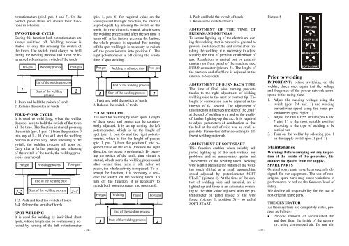
potentiometers (pic.1 pos. 6 and 7). On thecontrol panel there are shown their functionsin schemes.TWO-STROKE CYCLEDuring this function both potentiometers arealways switched off. Welding process isstarted by only the pressing the switch ofthe torch. The switch must always be heldduring the welding process and it can be interruptedreleasing the switch of the torch.11. Push and hold the switch of torch2. Release the switch of torchFOUR-WORK CYCLEIt is used to weld long, when the welderdoes not have to hold the switch of the torchall the time. The function is started pressingthe switch (pic. 1 pos. 7) from the position 0into any of 1 – 10.You will start the weldingprocess in such a way. After releasing of theswitch, the welding process still goes on.Only after a further pressing and releasingof the switch of the torch, the welding processis interrupted.1-2Pre-gasPre-gasWelding procesEnd of the welding processStart of the weldingprocessWelding processEnd of the welding procStart of the welding process1-2. Push and hold the switch of torch3-4. Release the switch of torchPost-gasSPOT WELDINGIt is used for welding by individual shortspots, whose length can be continuously adjustedby turning of the left potentiometer2Post-gas3-4- 34 -(pic. 1, pos. 6) for required value on thescale (toward the right direction, the intervalis prolonged). By pressing the switch on thetorch, the time circuit is started, which startsthe welding process and after the set time itturns off. After further pressing the button,the whole process is repeated. For turningoff the spot welding it is necessary to switchoff the potentiometer into position 0. Theright potentiometer is off during the wholetime of spot welding.Pre-gasWelding in adjusted timeEnd of the welding process1Start of the welding process1. Push and hold the switch of torch2. Release the switch of torchPost-gasPULSE WELDINGIt is used for welding by short spots. Lengthof these spots and pauses can be continuouslyadjusted. It is set up turning the leftpotentiometer, which is for the lenght ofspot (pic. 1, pos. 6) and the right potentiometer,which is for the lenght of pauses(pic. 1, pos. 7) from the position 0 into requiredvalue on the scale (towards the rightdirection, the pause is prolonged). By pressingthe switch of the torch, time circuit isstarted, which starts the welding process andafter certain time turns it off. After setpause, the whole activity is repeated. To interruptthe function, it is necessary to realeasethe switch on the welding torch. Toturn off the function, it is necessary toswitch both potentiometers into position 0.Pre-gasWeldingPauseEnd of the welding process1Start of the welding process2Post-gas21. Push and hold the switch of torch2. Release the switch of torchADJUSTMENT OF THE TIME OFPREGAS AND POSTGASTo secure lighting-up of the electric arc duringthe welding start in protective gas and toprevent oxidation of the end crater after finishingthe welding, it is necessary to adjustsuitably the time of preblow or afterblow ofgas. Regulation is carried out by potentiometerson front panel of the machine nextEURO connector (picture 4). The lenght ofthe preblow and afterblow is adjusted in theinterval 0-5 seconds.ADJUSTMENT OF BURN BACK TIMEThe time of final wire burning preventsthanks to the right adjustment of stickingwelding wire to the melt or contact tip. Thelenght of combustion can be adjusted in theinterval of 0-1 second. The adjustment ofthis function influences the size of the „ball“at the end of welding wire and so the qualityof further lighting-up the arc. It is requiredto adjust parameters of combustion so thatthe ball at the end of wire was as small aspossible. Parameters differ according to differentwelding materials.ADJUSTMENT OF SOFT STARTThis function enables when suitably adjustedlighting-up of the arch without anyproblems and no unnecessary spatter and„movement“ of the welding torch. Weldingwire is after pressing the button of the weldingtorch shifted at a small approachingspeed adjusted by potentiometer SOFTSTART (picture 4). At the time of the contactof welding wire and material, arc islighted-up and there is an automatic switchingto the shift value adjusted with the potentiometeron panel inside of the wirefeeder (picture 1, position 5) – so calledSOFT START.- 35 -Picture 4Prior to weldingIMPORTANT: before switching on thewelder, check once again that the voltageand frequency of the power network correspondto the rating plate.1. Adjust the welding voltage using theswitch (pos. 2,4 pict. 1) and weldingcurrent/wire speed using the panel potentiometer(pos. 5 pict. 1).2. Adjust the PROCESS switch (pos.6 and7 pict. 1) to the most suitable positionaccording to the type of welding to becarried out.3. Turn on the welder by selecting pos. 1on the supply switch (pos. 1 pict. 1).MaintenanceWarning: Before carrying out any inspectionof the inside of the generator, disconnectthe system from the supply.SPARE PARTSOriginal spare parts have been specially designedfor our equipment. The use of nonoriginalspare parts may cause variations inperformance or reduce the foreseen level ofsafety.We decline all responsibility for the use ofnon-original spare parts.THE GENERATORAs these systems are completely static, proceedas follows:• Periodic removal of accumulated dirtand dust from the inside of the generator,using compressed air. Do not aim