Datasheet - Source Photonics
Datasheet - Source Photonics
Datasheet - Source Photonics

Create successful ePaper yourself
Turn your PDF publications into a flip-book with our unique Google optimized e-Paper software.
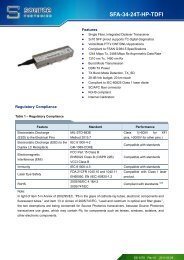
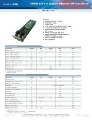
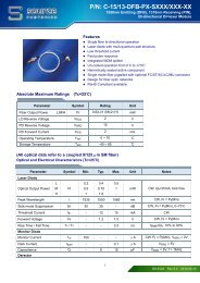
Feb 27, 2007155 Mbps SFP Transceiver with Spring Latch(With monitoring function, for 15km~80km transmission)Members of Flexon TM FamilyCompatible with FCC 47 CFR Part 15, Class BCompatible with FDA 21 CFR 1040.10 and1040.11, Class ICompliant with RoHSDescriptionFeatures Up to 155Mbps data-rate 1310nm FP laser and PIN photodetector for15km and 40km transmission 1550nm uncooled DFB laser and PINphotodetector for 80km transmission Digital diagnostic monitor interface compatiblewith SFF-8472 SFP MSA package with duplex LC connector With spring latch for easily removing Very low EMI and excellent ESD protection +3.3V single power supply Operating case temperature: 0 to +70°CFiberxon 155Mbps Spring-latch SFP transceiver ishigh performance, cost effective module thatsupports data-rate of 155Mbps and transmissiondistance from 15km to 80km.The transceiver consists of two sections: Thetransmitter section incorporates a FP or uncooledDFB laser, and the receiver section consists of aPIN photodiode integrated with a trans-impedancepreamplifier (TIA). All modules satisfy class I lasersafety requirements.The optical output can be disabled by a TTL logichigh-level input of Tx Disable. Tx Fault is provided toindicate degradation of the laser. Loss of signal(LOS) output is provided to indicate the loss of aninput optical signal of receiver.Applications SDH STM-1, S-1.1, L-1.1, L-1.2 SONET OC-3 IR1, LR1, LR2 Fast Ethernet Other optical linksStandardAn enhanced Digital Diagnostic Monitoring InterfaceCompatible with SFF-8472 has been incorporatedinto the transceivers. It allows real time access tothe transceiver operating parameters such astransceiver temperature, laser bias current,transmitted optical power, received optical powerand transceiver supply voltage by reading a built-inmemory with I 2 C interface. Compatible with SFP MSA Compatible with SFF-8472 Rev 9.5 Compatible with ITU-T G.957 and G.958 Compatible with Telcordia GR-253-COREFiberxon Proprietary and Confidential, Do Not Copy or Distribute Page 1 of 12
155Mbps Spring-latch SFP Transceiver15~80 km transmission with Monitoring function Preliminary <strong>Datasheet</strong> Feb 27, 2007Regulatory ComplianceThe transceivers have been tested according to American and European product safety and electromagneticcompatibility regulations (See Table 1). For further information regarding regulatory certification, please referto Fiberxon regulatory specification and safety guidelines, or contact with Fiberxon, Inc. America sales officelisted at the end of the documentation.Table 1- Regulatory ComplianceFeature Standard PerformanceElectrostatic Discharge MIL-STD-883E(ESD) to the Electrical Pins Method 3015.7Class 2(>2000 V)Electrostatic Discharge (ESD) IEC 61000-4-2to the Duplex LC Receptacle GR-1089-CORECompatible with standardsFCC Part 15 Class BElectromagneticEN55022 Class B (CISPR 22B)Interference (EMI)VCCI Class BCompatible with standardsImmunity IEC 61000-4-3 Compatible with standardsLaser Eye SafetyFDA 21CFR 1040.10 and 1040.11EN60950, EN (IEC) 60825-1,2Compatible with Class 1 laserproduct.Component Recognition UL and CSA Compatible with standards2002/95/EC 4.1&4.2Compliant with standards noteRoHS2005/747/ECNote:In light of item 5 in Annex of 2002/95/EC, “Pb in the glass of cathode ray tubes, electronic components andfluorescent tubes.” and item 13 in Annex of 2005/747/EC, “Lead and cadmium in optical and filter glass.”, thetwo exemptions are being concerned for Fiberxon’s transceivers, because Fiberxon’s transceivers use glass,which may contain Pb, for components such as lenses, windows, isolators, and other electronic components.Absolute Maximum RatingsStress in excess of the maximum absolute ratings can cause permanent damage to the module.Table 2 - Absolute Maximum RatingsParameter Symbol Min. Max. UnitStorage Temperature T S -40 +85 °CSupply Voltage V CC -0.5 3.6 VOperating Relative Humidity - 5 95 %Recommended Operating ConditionsTable 3- Recommended Operating ConditionsParameter Symbol Min. Typical Max. UnitOperating Case Temperature T C 0 +70 °CFiberxon Proprietary and Confidential, Do Not Copy or Distribute Page 2 of 12
155Mbps Spring-latch SFP Transceiver15~80 km transmission with Monitoring function Preliminary <strong>Datasheet</strong> Feb 27, 2007Power Supply Voltage V CC 3.13 3.47 VPower Supply Current I CC 300 mAData Rate 155 MbpsOptical and Electrical CharacteristicsAll parameters are specified at overall operating case temperature and power supply range, unless otherwisestated.FTM-3101C-SL15G (1310nm FP and PIN, 15km, Monitoring function)Table 4 - Optical and Electrical CharacteristicsParameter Symbol Min. Typical Max. Unit NotesTransmitterCentre Wavelength λ C 1261 1360 nmAverage Output Power P 0ut -15 -8 dBm 1Spectral Width (RMS) σ 4 nmExtinction Ratio EX 8.2 dBJitter Generation (RMS) 0.01 UIJitter Generation (pk-pk) 0.1 UIOutput Optical EyeCompatible with Telcordia GR-253-CORE and ITU-TG.9572Data Input Swing Differential V IN 300 1860 mV 3Input Differential Impedance Z IN 90 100 110 ΩTX DisableDisable 2.0 Vcc VEnable 0 0.8 VTX FaultFault 2.0 Vcc+0.3 VNormal 0 0.8 VReceiverCentre Wavelength λ C 1260 1580 nmReceiver Sensitivity -34 dBm 4Receiver Overload -8 dBm 4Optical Path Penalty 1 dB 5LOS De-Assert LOS D -37 dBmLOS Assert LOS A -45 dBmLOS Hysteresis 1 4 dBData Output Swing Differential V OUT 370 1800 mV 6LOSHigh 2.0 Vcc+0.3 VLow 0 0.8 VNotes:1. The optical power is launched into SMF.2. Measured with a PRBS 2 23 -1 test pattern @155Mbps.3. Internally AC coupled and terminated.Fiberxon Proprietary and Confidential, Do Not Copy or Distribute Page 3 of 12
155Mbps Spring-latch SFP Transceiver15~80 km transmission with Monitoring function Preliminary <strong>Datasheet</strong> Feb 27, 20074. Measured with a PRBS 2 23 -1 test pattern @155Mbps, BER ≤1×10 -10 .5. Measured with a PRBS 2 23 -1 test pattern @155Mbps, over 15km G.652 SMF, BER ≤1×10 -10 .6. Internally AC coupled.FTM-3101C-SL40G (1310nm FP and PIN, 40km, Monitoring function)Table 5 - Optical and Electrical CharacteristicsParameter Symbol Min. Typical Max. Unit NotesTransmitterCentre Wavelength λ C 1263 1360 nmAverage Output Power P 0ut -5 0 dBm 1Spectral Width (RMS) σ 3 nmExtinction Ratio EX 10 dBJitter Generation (RMS) 0.01 UIJitter Generation (pk-pk) 0.1 UIOutput Optical EyeCompatible with Telcordia GR-253-CORE and ITU-TG.9572Data Input Swing Differential V IN 300 1860 mV 3Input Differential Impedance Z IN 90 100 110 ΩTX DisableDisable 2.0 Vcc VEnable 0 0.8 VTX FaultFault 2.0 Vcc+0.3 VNormal 0 0.8 VReceiverCentre Wavelength λ C 1260 1580 nmReceiver Sensitivity -34 dBm 4Receiver Overload -8 dBm 4Optical Path Penalty 1 dB 5LOS De-Assert LOS D -37 dBmLOS Assert LOS A -45 dBmLOS Hysteresis 1 4 dBData Output Swing Differential V OUT 370 1800 mV 6LOSHigh 2.0 Vcc+0.3 VLow 0 0.8 VNotes:1. The optical power is launched into SMF.2. Measured with a PRBS 2 23 -1 test pattern @155Mbps.3. Internally AC coupled and terminated.4. Measured with a PRBS 2 23 -1 test pattern @155Mbps, BER ≤1×10 -10 .5. Measured with a PRBS 2 23 -1 test pattern @155Mbps, over 40km G.652 SMF, BER ≤1×10 -10 .6. Internally AC coupled.Fiberxon Proprietary and Confidential, Do Not Copy or Distribute Page 4 of 12
155Mbps Spring-latch SFP Transceiver15~80 km transmission with Monitoring function Preliminary <strong>Datasheet</strong> Feb 27, 2007FTM-5101C-SL80G (1550nm DFB and PIN, 80km, Monitoring function)Table 6 - Optical and Electrical CharacteristicsParameter Symbol Min. Typical Max. Unit NotesTransmitterCentre Wavelength λ C 1480 1580 nmAverage Output Power P 0ut -5 0 dBm 1Spectral Width (-20dB) ∆λ 1 nmSide Mode Suppression Ratio SMSR 30 dBExtinction Ratio EX 10 dBJitter Generation (RMS) 0.01 UIJitter Generation (pk-pk) 0.1 UIOutput Optical EyeCompatible with Telcordia GR-253-CORE and ITU-TG.9572Data Input Swing Differential V IN 300 1860 mV 3Input Differential Impedance Z IN 90 100 110 ΩTX DisableDisable 2.0 Vcc VEnable 0 0.8 VTX FaultFault 2.0 Vcc+0.3 VNormal 0 0.8 VReceiverCentre Wavelength λ C 1260 1580 nmReceiver Sensitivity -34 dBm 4Receiver Overload -8 dBmOptical Path Penalty 1 dB 5LOS De-Assert LOS D -37 dBmLOS Assert LOS A -45 dBmLOS Hysteresis 1 4 dBData Output Swing Differential V OUT 370 1800 mV 6LOSHigh 2.0 Vcc+0.3 VLow 0 0.8 VNotes:1. The optical power is launched into SMF.2. Measured with a PRBS 2 23 -1 test pattern @155Mbps.3. Internally AC coupled and terminated.4. Measured with a PRBS 2 23 -1 test pattern @155Mbps, BER ≤1×10 -10 .5. Measured with a PRBS 2 23 -1 test pattern @155Mbps, over 80km G.652 SMF, BER ≤1×10 -10 .6. Internally AC coupled.EEPROM InformationThe SFP MSA defines a 256-byte memory map in EEPROM describing the transceiver’s capabilities,standard interfaces, manufacturer, and other information, which is accessible over a 2 wire serial interface atthe 8-bit address 1010000X (A0h). The memory contents refer to Table 7.Fiberxon Proprietary and Confidential, Do Not Copy or Distribute Page 5 of 12
155Mbps Spring-latch SFP Transceiver15~80 km transmission with Monitoring function Preliminary <strong>Datasheet</strong> Feb 27, 2007Table 7 - EEPROM Serial ID Memory Contents (A0h)Field SizeAddr. Name of Field(Bytes)Hex Description0 1 Identifier 03 SFP1 1 Ext. Identifier 04 MOD42 1 Connector 07 LC3—10 8 Transceiver 00 xx xx 00 00 00 00 00 OC 3, Single mode inter. or long reach11 1 Encoding 03 NRZ12 1 BR, nominal 02 155Mbps13 1 Reserved 0014 1 Length (9um)-km 0F/28/50 15km/40km/80km15 1 Length (9um) 96/FF/FF 15km/40km/80km16 1 Length (50um) 0017 1 Length (62.5um) 0018 1 Length (copper) 0019 1 Reserved 0020—35 16 Vendor name46 49 42 45 52 58 4F 4E20 49 4E 43 2E 20 20 20“FIBERXON INC. “(ASCⅡ)36 1 Reserved 0037—39 3 Vendor OUI 00 00 0040—55 16 Vendor PN46 54 4D 2D xx 31 30 3143 2D 53 4C xx xx 47 20“FTM-x101C-SLxxG ” (ASC Ⅱ )56—59 4 Vendor rev xx xx 20 20 ASC Ⅱ ( “31 30 20 20” means 1.0 revision)60-61 2 Wavelength 05 1E/06 0E 1310nm/1550nm62 1 Reserved 0063 1 CC BASE xx Check sum of bytes 0 - 6264—65 2 Options 00 1A LOS, TX_FAULT and TX_DISABLE66 1 BR, max 0067 1 BR, min 0068—83 16 Vendor SNxx xx xx xx xx xx xx xxxx xx xx xx xx xx xx xxASC Ⅱ .84—91 8 Vendor date codexx xx xx xx xx xx 20 20 Year (2 bytes), Month (2 bytes), Day (2 bytes)92 1 Diagnostic type 58 Diagnostics(Ext.Cal)93 1 Enhanced option B0Diagnostics (Optional Alarm/warning flags,Soft TX_FAULT and Soft TX_LOS monitoring)94 1 SFF-8472 02 Diagnostics(SFF-8472 Rev 9.4)95 1 CC EXT xx Check sum of bytes 64 - 9496—255 160 Vendor specificNote: The “xx” byte should be filled in according to practical case. For more information, please refer to therelated document of SFF-8472 Rev 9.5.Monitoring SpecificationFiberxon Proprietary and Confidential, Do Not Copy or Distribute Page 6 of 12
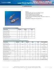
155Mbps Spring-latch SFP Transceiver15~80 km transmission with Monitoring function Preliminary <strong>Datasheet</strong> Feb 27, 2007The digital diagnostic monitoring interface also defines another 256-byte memory map in EEPROM, whichmakes use of the 8 bit address 1010001X (A2h). Please see Figure 1. For detail EEPROM information,please refer to the related document of SFF-8472 Rev 9.5. The monitoring specification of this product isdescribed in Table 8.Figure 1, EEPROM Memory Map Specific Data Field DescriptionsTable 8- Monitoring SpecificationParameter Range Accuracy CalibrationTemperature -10 to 80°C ±3°C ExternalVoltage 3.0 to 3.6V ±3% ExternalBias Current 0 to 100mA ±10% ExternalFTM-3101C-SL15G -16 to –7 dBmTX Power FTM-3101C-SL40G -6 to +1 dBm±3dBExternalFTM-5101C-SL80G -6 to +1 dBmFTM-3101C-SL15G -30 to –7 dBmRX Power FTM-3101C-SL40G -34 to –9 dBm±3dBExternalFTM-5101C-SL80G -34 to –9 dBmRecommended Host Board Power Supply CircuitFigure 2 shows the recommended host board power supply circuit.Fiberxon Proprietary and Confidential, Do Not Copy or Distribute Page 7 of 12
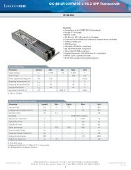
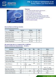
155Mbps Spring-latch SFP Transceiver15~80 km transmission with Monitoring function Preliminary <strong>Datasheet</strong> Feb 27, 2007Figure 2, Recommended Host Board Power Supply CircuitRecommended Interface CircuitFigure 3 shows the recommended interface circuit.Host BoardVcc (+3.3V)2×4.7K to 10KTX DisableSFP ModuleVccT10KTX FaultSerDat Out +Z=50TD +ProtocolICSERDESICSerDat Out -SerDat In +Z=50Z=50TD -RD +LaserdriverSerDat In -Z=50RD -AmplifierLOSVcc (+3.3V)3×4.7K to 10KMOD-DEF2MOD-DEF1MOD-DEF0EEPROMRGNDPin DefinitionsFigure 3, Recommended Interface CircuitFigure 4 below shows the pin numbering of SFP electrical interface. The pin functions are described in Table 9with some accompanying notes.Fiberxon Proprietary and Confidential, Do Not Copy or Distribute Page 8 of 12
155Mbps Spring-latch SFP Transceiver15~80 km transmission with Monitoring function Preliminary <strong>Datasheet</strong> Feb 27, 2007TOP VIEWOF BOARDPin 20Pin 11Pin 10BOTTOM VIEWOF BOARDPin 1Figure 4, Pin ViewTable 9 - Pin Function DefinitionsPin No. Name Function Plug Seq. Notes1 VeeT Transmitter Ground 12 TX Fault Transmitter Fault Indication 3 Note 13 TX Disable Transmitter Disable 3 Note 24 MOD-DEF2 Module Definition 2 3 Note 35 MOD-DEF1 Module Definition 1 3 Note 36 MOD-DEF0 Module Definition 0 3 Note 37 Rate Select Not Connected 38 LOS Loss of Signal 3 Note 49 VeeR Receiver Ground 110 VeeR Receiver Ground 111 VeeR Receiver Ground 112 RD- Inv. Received Data Out 3 Note 513 RD+ Received Data Out 3 Note 514 VeeR Receiver Ground 115 VccR Receiver Power 216 VccT Transmitter Power 217 VeeT Transmitter Ground 118 TD+ Transmit Data In 3 Note 619 TD- Inv. Transmit Data In 3 Note 620 VeeT Transmitter Ground 1Notes:1. TX Fault is an open collector output, which should be pulled up with a 4.7k~10kΩ resistor on the hostboard to a voltage between 2.0V and Vcc+0.3V. Logic 0 indicates normal operation; logic 1 indicates alaser fault of some kind. In the low state, the output will be pulled to less than 0.8V.2. TX Disable is an input that is used to shut down the transmitter optical output. It is pulled up within themodule with a 4.7k~10kΩ resistor. Its states are:Low (0~0.8V):Transmitter on(>0.8V,
155Mbps Spring-latch SFP Transceiver15~80 km transmission with Monitoring function Preliminary <strong>Datasheet</strong> Feb 27, 2007Open:Transmitter Disabled3. MOD-DEF 0,1,2 are the module definition pins. They should be pulled up with a 4.7k~10kΩ resistor onthe host board. The pull-up voltage shall be VccT or VccR.MOD-DEF 0 is grounded by the module to indicate that the module is presentMOD-DEF 1 is the clock line of two wires serial interface for serial IDMOD-DEF 2 is the data line of two wires serial interface for serial ID4. LOS is an open collector output, which should be pulled up with a 4.7k~10kΩ resistor on the host board toa voltage between 2.0V and Vcc+0.3V. Logic 0 indicates normal operation; logic 1 indicates loss of signal.In the low state, the output will be pulled to less than 0.8V.5. These are the differential receiver output. They are internally AC-coupled 100Ω differential lines whichshould be terminated with 100Ω (differential) at the user SERDES.6. These are the differential transmitter inputs. They are AC-coupled, differential lines with 100Ω differentialtermination inside the module.Mechanical Design DiagramThe mechanical design diagram is shown in Figure 5.Figure 5, Mechanical Design Diagram of the SFP with Spring LatchOrdering informationFiberxon Proprietary and Confidential, Do Not Copy or Distribute Page 10 of 12
155Mbps Spring-latch SFP Transceiver15~80 km transmission with Monitoring function Preliminary <strong>Datasheet</strong> Feb 27, 2007FTM x 1 0 1 C S L x xGWavelength3 : 1310nm5 : 1550nmFunction1: MonitoringData rate01: 155MReceptacleC : LCPackageSL: SFP with spring latchDistance15 : 15 km40 : 40 km80:80 kmOthersG: RoHS CompliancePart No.FTM-3101C-SL15GFTM-3101C-SL40GFTM-5101C-SL80GProduct Description1310nm, 155Mbps, 15km, SFP with spring latch, Monitoring function, 0°C~+70°C,RoHScompliance1310nm, 155Mbps, 40km, SFP with spring latch, Monitoring function, 0°C~+70°C,RoHScompliance1550nm, 155Mbps, 80km, SFP with spring latch, Monitoring function, 0°C~+70°C,RoHScomplianceRelated DocumentsFor further information, please refer to the following documents:■ Fiberxon SFP Application Notes■ SFP Multi-<strong>Source</strong> Agreement (MSA)■ SFF-8472 Rev 9.5Obtaining DocumentYou can visit our website:http://www.fiberxon.comOr contact Fiberxon, Inc. America Sales Office listed at the end of the documentation to get the latestdocuments.Revision HistoryRevision Initiate Review Approve Subject Release DateRev. 1a Solaris Zhu Simon Jiang Walker.Wei Initial datasheet Feb 27, 2007© Copyright Fiberxon Inc. 2007All Rights Reserved.All information contained in this document is subject to change without notice. The products described in thisdocument are NOT intended for use in implantation or other life support applications where malfunction mayFiberxon Proprietary and Confidential, Do Not Copy or Distribute Page 11 of 12
155Mbps Spring-latch SFP Transceiver15~80 km transmission with Monitoring function Preliminary <strong>Datasheet</strong> Feb 27, 2007result in injury or death to persons.The information contained in this document does not affect or change Fiberxon’s product specifications orwarranties. Nothing in this document shall operate as an express or implied license or indemnity under theintellectual property rights of Fiberxon or third parties. All information contained in this document was obtainedin specific environments, and is presented as an illustration. The results obtained in other operatingenvironment may vary.THE INFORMATION CONTAINED IN THIS DOCUMENT IS PROVIDED ON AN ”AS IS” BASIS. In no eventwill Fiberxon be liable for damages arising directly from any use of the information contained in this document.ContactU.S.A. Headquarter:5201 Great America Parkway, Suite 340Santa Clara, CA 95054U. S. A.Tel: 408-562-6288Fax: 408-562-6289Or visit our website: http://www.fiberxon.comFiberxon Proprietary and Confidential, Do Not Copy or Distribute Page 12 of 12