Modules - Beriled
Modules - Beriled
Modules - Beriled

You also want an ePaper? Increase the reach of your titles
YUMPU automatically turns print PDFs into web optimized ePapers that Google loves.
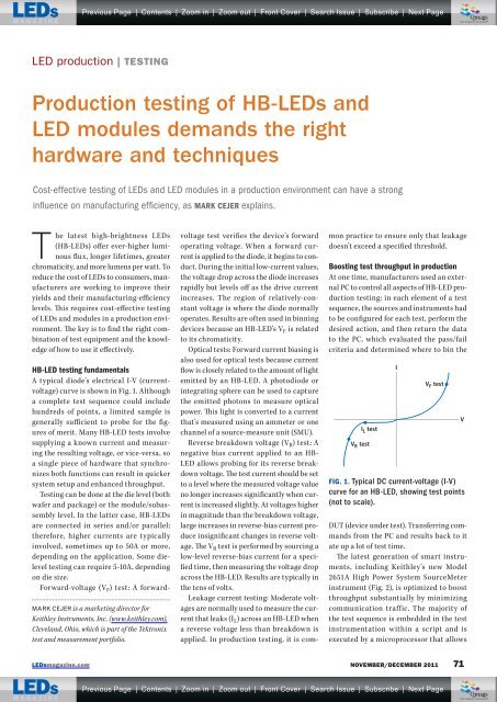
Previous Page | Contents | Zoom in | Zoom out | Front Cover | Search Issue | SubscribeqMqM | Next PageqqM qMMQmagsTHE WORLD’S NEWSSTAND ®LED production | TESTINGProduction testing of HB-LEDs andLED modules demands the righthardware and techniquesCost-effective testing of LEDs and LED modules in a production environment can have a stronginfl uence on manufacturing effi ciency, as MARK CEJER explains.The latest high-brightness LEDs(HB-LEDs) offer ever-higher luminousflux, longer lifetimes, greaterchromaticity, and more lumens per watt. Toreduce the cost of LEDs to consumers, manufacturersare working to improve theiryields and their manufacturing-efficiencylevels. This requires cost-effective testingof LEDs and modules in a production environment.The key is to find the right combinationof test equipment and the knowledgeof how to use it effectively.MARK CEJER is a marketing director forKeithley Instruments, Inc. (www.keithley.com),Cleveland, Ohio, which is part of the Tektronixtest and measurement portfolio.HB-LED testing fundamentalsA typical diode’s electrical I-V (currentvoltage)curve is shown in Fig. 1. Althougha complete test sequence could includehundreds of points, a limited sample isgenerally sufficient to probe for the figuresof merit. Many HB-LED tests involvesupplying a known current and measuringthe resulting voltage, or vice-versa, soa single piece of hardware that synchronizesboth functions can result in quickersystem setup and enhanced throughput.Testing can be done at the die level (bothwafer and package) or the module/subassemblylevel. In the latter case, HB-LEDsare connected in series and/or parallel;therefore, higher currents are typicallyinvolved, sometimes up to 50A or more,depending on the application. Some dieleveltesting can require 5-10A, dependingon die size.Forward-voltage (V F ) test: A forwardvoltagetest verifies the device’s forwardoperating voltage. When a forward currentis applied to the diode, it begins to conduct.During the initial low-current values,the voltage drop across the diode increasesrapidly but levels off as the drive currentincreases. The region of relatively-constantvoltage is where the diode normallyoperates. Results are often used in binningdevices because an HB-LED’s V F is relatedto its chromaticity.Optical tests: Forward current biasing isalso used for optical tests because currentflow is closely related to the amount of lightemitted by an HB-LED. A photodiode orintegrating sphere can be used to capturethe emitted photons to measure opticalpower. This light is converted to a currentthat’s measured using an ammeter or onechannel of a source-measure unit (SMU).Reverse breakdown voltage (V R ) test: Anegative bias current applied to an HB-LED allows probing for its reverse breakdownvoltage. The test current should be setto a level where the measured voltage valueno longer increases significantly when currentis increased slightly. At voltages higherin magnitude than the breakdown voltage,large increases in reverse-bias current produceinsignificant changes in reverse voltage.The V R test is performed by sourcing alow-level reverse-bias current for a specifiedtime, then measuring the voltage dropacross the HB-LED. Results are typically inthe tens of volts.Leakage current testing: Moderate voltagesare normally used to measure the currentthat leaks (I L ) across an HB-LED whena reverse voltage less than breakdown isapplied. In production testing, it is commonpractice to ensure only that leakagedoesn’t exceed a specified threshold.Boosting test throughput in productionAt one time, manufacturers used an externalPC to control all aspects of HB-LED productiontesting; in each element of a testsequence, the sources and instruments hadto be configured for each test, perform thedesired action, and then return the datato the PC, which evaluated the pass/failcriteria and determined where to bin theI L testV R testIV F testFIG. 1. Typical DC current-voltage (I-V)curve for an HB-LED, showing test points(not to scale).DUT (device under test). Transferring commandsfrom the PC and results back to itate up a lot of test time.The latest generation of smart instruments,including Keithley’s new Model2651A High Power System SourceMeterinstrument (Fig. 2), is optimized to boostthroughput substantially by minimizingcommunication traffic. The majority ofthe test sequence is embedded in the testinstrumentation within a script and isexecuted by a microprocessor that allowsVLEDsmagazine.com NOVEMBER/DECEMBER 2011 71Previous Page | Contents | Zoom in | Zoom out | Front Cover | Search Issue | SubscribeqMqM qMM MQmags| Next Page q qTHE WORLD’S NEWSSTAND ®