miniLAB 1008 User's Guide - eConceptOnline
miniLAB 1008 User's Guide - eConceptOnline
miniLAB 1008 User's Guide - eConceptOnline

Create successful ePaper yourself
Turn your PDF publications into a flip-book with our unique Google optimized e-Paper software.
<strong>miniLAB</strong> <strong>1008</strong> <strong>User's</strong> <strong>Guide</strong> Functional Details<br />
Single-ended configuration<br />
When all of the analog input channels are configured for single-ended input mode, eight analog channels<br />
are available. In single-ended mode, the input signal is referenced to signal ground (GND). The input<br />
signal is delivered through two wires:<br />
� The wire carrying the signal to be measured connects to CH# IN.<br />
� The second wire connects to GND.<br />
The input range for single-ended mode is ±10 V, max, with a gain of 2. No other gains are supported in<br />
single-ended mode.<br />
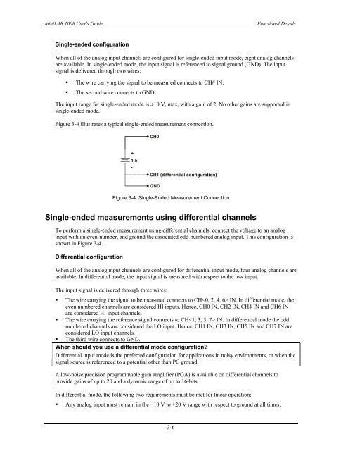
Figure 3-4 illustrates a typical single-ended measurement connection.<br />
+<br />
1.5<br />
-<br />
CH0<br />
CH1 (differential configuration)<br />
GND<br />
Figure 3-4. Single-Ended Measurement Connection<br />
Single-ended measurements using differential channels<br />
To perform a single-ended measurement using differential channels, connect the voltage to an analog<br />
input with an even-number, and ground the associated odd-numbered analog input. This configuration is<br />
shown in Figure 3-4.<br />
Differential configuration<br />
When all of the analog input channels are configured for differential input mode, four analog channels are<br />
available. In differential mode, the input signal is measured with respect to the low input.<br />
The input signal is delivered through three wires:<br />
� The wire carrying the signal to be measured connects to CH IN. In differential mode, the<br />
even numbered channels are considered HI inputs. Hence, CH0 IN, CH2 IN, CH4 IN and CH6 IN<br />
are considered HI input channels.<br />
� The wire carrying the reference signal connects to CH IN. In differential mode the odd<br />
numbered channels are considered the LO input. Hence, CH1 IN, CH3 IN, CH5 IN and CH7 IN are<br />
considered LO input channels.<br />
� The third wire connects to GND.<br />
When should you use a differential mode configuration?<br />
Differential input mode is the preferred configuration for applications in noisy environments, or when the<br />
signal source is referenced to a potential other than PC ground.<br />
A low-noise precision programmable gain amplifier (PGA) is available on differential channels to<br />
provide gains of up to 20 and a dynamic range of up to 16-bits.<br />
In differential mode, the following two requirements must be met for linear operation:<br />
� Any analog input must remain in the −10 V to +20 V range with respect to ground at all times.<br />
3-6