miniLAB 1008 User's Guide - eConceptOnline
miniLAB 1008 User's Guide - eConceptOnline
miniLAB 1008 User's Guide - eConceptOnline

You also want an ePaper? Increase the reach of your titles
YUMPU automatically turns print PDFs into web optimized ePapers that Google loves.
<strong>miniLAB</strong> <strong>1008</strong> <strong>User's</strong> <strong>Guide</strong> Functional Details<br />
Since the analog inputs are restricted to a −10 V to +20 V signal swing with respect to ground, all ranges<br />
except ±20 V can realize a linear output for any differential signal with zero common mode voltage and<br />
full scale signal inputs. The ±20 V range is the exception. You cannot put −20 V on CHHI, and 0 V on<br />
CHLO, since this violates the input range criteria. Table 3-3 shows some possible inputs and the expected<br />
results.<br />
Table 3-3. Sample Inputs and Differential Results<br />
CHHI CHLO Result<br />
-20 V 0 V Invalid<br />
-15 V +5 V Invalid<br />
-10 V 0 V -10 V<br />
-10 V +10 V -20 V<br />
0 V +10 V -10 V<br />
0 V +20 V -20 V<br />
+10 V -10 V +20 V<br />
+10 V 0 V +10 V<br />
+15 V -5 V +20 V<br />
+20 V 0 +20 V<br />
Additional information on analog signal connections<br />
For general information regarding single-ended and differential inputs, refer to the <strong>Guide</strong> to Signal<br />
Connections (available on our web site at www.mccdaq.com/signals/signals.pdf).<br />
Digital I/O terminals (DIO0 - DIO3)<br />
Connect up to four digital I/O lines to the screw terminals containing pins DIO0 to DIO3. Refer to the<br />
pinout diagrams on page 3-5 for the location of these pins. You can configure each digital channel<br />
independently for either input or output.<br />
Overvoltage/short circuit protection is provided with a 1.5 kΩ series resistor on each I/O pin. Use of the<br />
resistor may limit the value of the output current, however. For example, if the output current is 1 mA, the<br />
resistor drops 1.5 V, resulting in an output of 3.5 V.<br />
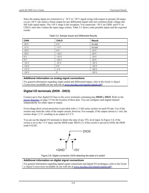
You can use the digital I/O terminals to detect the state of any TTL level input. In Figure 3-8, if the<br />
switch is set to the +5 V input, and the DIO0 reads TRUE (1). If the switch is moved to GND, the DIO0<br />
reads FALSE.<br />
+GND<br />
+5V<br />
DIO0<br />
Figure 3-8. Digital connection DIO0 detecting the state of a switch<br />
Additional information on digital signal connections<br />
For general information regarding digital signal connections and digital I/O techniques, refer to the <strong>Guide</strong><br />
to Signal Connections (available on our web site at www.mccdaq.com/signals/signals.pdf).<br />
3-8