Unvented Cylinder Manual - BHL.co.uk
Unvented Cylinder Manual - BHL.co.uk
Unvented Cylinder Manual - BHL.co.uk

Create successful ePaper yourself
Turn your PDF publications into a flip-book with our unique Google optimized e-Paper software.
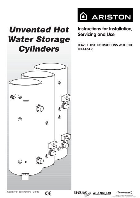
<strong>Unvented</strong> HotWater Storage<strong>Cylinder</strong>sInstructions for Installation,Servicing and UseLEAVE THESE INSTRUCTIONS WITH THEEND-USERCountry of destination:GB/IE
TABLE OF CONTENTS1. GENERAL INFORMATION Page 31.1 Guarantee Page 31.2 Delivery Page 32. INSTALLATION Page 42.1 Water Regulations Page 42.2 Building Regulations Page 42.3 General Guidance Page 42.4 How the Appliance Works Page 52.5 Cold Water Supply Page 52.6 Siting and Fixing Page 52.7 Overall Dimensions Page 72.8 Connection of Mains Supply Page 82.9 Cold Water Combination Valve Page 112.10 Connection to Services Page 132.11 Se<strong>co</strong>ndary Return Page 132.12 Discharge Pipework Page 132.13 Electrical Connection Page 162.14 Electrical Diagrams Page 183. COMMISSIONING Page 214. MAINTENANCE Page 234.1 ProTech Anti-<strong>co</strong>rrosion System Page 234.2 Thermal Cut-out(s) Page 234.3 Immersion Heater(s) Page 234.4 <strong>Unvented</strong> Controls Page 234.5 Thermostats Page 244.6 Maintenance Page 245. FAULT FINDING Page 266. TECHNICAL INFORMATION Page 272
1. GENERALINFORMATIONThis manual is an integral and essential part of the product. It should be keptwith the appliance so that it can be <strong>co</strong>nsulted by the user and our authorisedpersonnel.Please read carefully the instructions and notices about the appliance<strong>co</strong>ntained in this manual, as they provide important information regarding thesafe installation, use and maintenance of the cylinder.Failure to do so may invalidate the guarantee.When installing and servicing the cylinder, MTS re<strong>co</strong>mmend the use ofprotective clothing i.e. gloves.1.1 GUARANTEEThe MTS range of unvented cylinders <strong>co</strong>me with varying guaranteesdepending on the model of cylinder. The guarantee periods offered witheach model of cylinder are as follows:ST Range - 10 Years tank- 2 Years electrical <strong>co</strong>mponentsClassi<strong>co</strong> Range - 5 Years tank- 2 Years electrical <strong>co</strong>mponentsPrimo Range - 25 Years tank- 2 Years electrical <strong>co</strong>mponentsHigh Capacity Range - 10 Years tank- 2 Years electrical <strong>co</strong>mponentsNote: The guarantee is subject to the cylinder being installed and servicedannually by a <strong>co</strong>mpetent person as per the servicing instructions in Section4.6 of this manual. For units with the ProTech anti-<strong>co</strong>rrosion device it mustbe ensured that this is <strong>co</strong>nnected and operating <strong>co</strong>rrectly (green LED only).1.2 DELIVERYThe MTS range of <strong>Unvented</strong> <strong>Cylinder</strong>s are available in the following options:The Wall-hung ProTech range (50, 75, 100 litre models), which are suppliedas follows;One box <strong>co</strong>ntaining;1) The cylinder with factory fitted temperature & pressure relief valve,immersion heater and thermostat with thermal cut-out.One box <strong>co</strong>ntaining;1) <strong>Unvented</strong> <strong>co</strong>ntrol pack (expansion vessel, 2 piece <strong>co</strong>ld water <strong>co</strong>mbinationvalve and tundish), instructions for installation, servicing and use and theBenchmark Log Book).The High Capacity ProTech floor-standing range (500 litre models), whichare supplied as follows;One box <strong>co</strong>ntaining;1) The cylinder with factory fitted temperature & pressure relief valve.One box <strong>co</strong>ntaining;1) <strong>Unvented</strong> <strong>co</strong>ntrol pack (expansion vessel, 2 piece <strong>co</strong>ld water <strong>co</strong>mbinationvalve and tundish), motorised valve (indirect only, non-high temperature).Immersion heater(s) and thermostat(s) with thermal cut-out(s), cylinderthermostat with thermal cut-out (indirect only), feet (x 3), instructions forinstallation, servicing and use and the Benchmark Log Book.The STD and STI and the ITD and ITI floor standing ranges (125, 150, 200and 300 litre models) which are supplied as follows;One box <strong>co</strong>ntaining;1) The cylinder with factory fitted temperature & pressure relief valve.3
One box <strong>co</strong>ntaining;1) <strong>Unvented</strong> <strong>co</strong>ntrol pack (expansion vessel, 2 piece <strong>co</strong>ld water <strong>co</strong>mbinationvalve and tundish), motorised valve (indirect only, non-high temperature).Immersion heater(s) and thermostat(s) with thermal cut-out(s), cylinderthermostat with thermal cut-out (indirect only), feet (x3), expansionvessel mounting bracket and hose, instructions for installation, servicingand use and the Benchmark Log Book.The ITSI twin <strong>co</strong>il floor standing range (200 and 300 litre models) aresupplied with the following;One box <strong>co</strong>ntaining;1) The cylinder with factory fitted temperature & pressure relief valve.One box <strong>co</strong>ntaining;1) <strong>Unvented</strong> <strong>co</strong>ntrol pack (expansion vessel, 2 piece <strong>co</strong>ld water <strong>co</strong>mbinationvalve and tundish), 2 x motorised valves (non-high temperature), 2 xImmersion heaters and thermostats with thermal cut-out, 2 x cylinderthermostats with thermal cut-out, 1 x elongated thermostat pocket (forsolar applications), feet (x3), expansion vessel mounting bracket andhose, instructions for installation, servicing and use and the BenchmarkLog Book.2. INSTALLATION2.1 WATER REGULATIONS2.2 BUILDING REGULATIONS2.3 GENERAL GUIDANCEThe appliance should be installed in ac<strong>co</strong>rdance with the Domestic HeatingCompliance Guide.These regulations (byelaws in S<strong>co</strong>tland) ensure a good supply ofwholesome water, and that only approved materials, pipes and fittings areused to <strong>co</strong>nvey water.These are a statutory document and take priority over all other regulationsand re<strong>co</strong>mmendations. The installation of an unvented hot water storagecylinder is classified as a “Controlled Service” and Regulation G3 applies. Tomeet the requirements of the Regulation, installation of an unvented systemshould be undertaken by a “<strong>co</strong>mpetent installer”.All installations of unvented hot water storage systems having a capacity ofmore than 15 litres should be notified to the relevant Local Authority bymeans of building notice or by the submission of full plans. It is important tonote that it is a criminal offense to install an unvented hot water storagesystem without notifying the Local Authority. The installation of the unventedcylinder and hot water system must <strong>co</strong>mply with BS 6700 and the HSELegionella Code of Practice.Current guidance notes do not <strong>co</strong>ver the <strong>co</strong>nnection of a solar thermalcircuit to an unvented storage vessel (cylinder). However, if guidance issought for <strong>co</strong>mpliance with current regulations the fundamental principle isto provide a failsafe means of shutting off the solar input to the heatexchanger if the cylinder temperature should rise above the set temperatureof the cylinder’s energy cut out. (See Note 1).As with all unvented hot water systems, notification of intention to installshould be given to your local building <strong>co</strong>ntrol.Option A. A non self resetting mechanical shut-off should be installed onthe solar primary flow to the cylinder. The mechanical shut-off should besuitable for use with a solar primary circuit (i.e. high temperature and gly<strong>co</strong>lresistant). The mechanical shut-off should be integrated electrically with thecylinder energy cut out/s and if necessary the solar circuit temperature<strong>co</strong>ntrol, please refer to the solar <strong>co</strong>ntroller manufacturer for furtherinformation.Option B. Where the solar <strong>co</strong>ntroller and hydraulic system demonstrate thatby no lesser means the requirement in Option A is satisfied by other means;certification by an approvals body is required to demonstrate that in theevent of the stored water going over temperature, the heat input to thecylinder is isolated by physical means and is non self resetting.These systems should be clearly identified with reference to the approvals4
ody. (See Note 2)Note 1 :Whilst most solar cylinders use a <strong>co</strong>il type heat exchanger otheroptions such as external plate to plate devices , external annulars or ‘tank intank’ systems may be used but the same <strong>co</strong>ntrol options always apply.Note 2 :Current approved bodies include the British Board of Agrement(BBA) , WRc-NSF Limited, or KIWA2.4 HOW THE APPLIANCEWORKSThe immersion heater(s) are <strong>co</strong>ntrolled through a thermostat which sensesthe water temperature. The operating temperature can be pre-set byadjusting the spindle in the head of the thermostat. In addition to thethermostat there is a thermal cut-out in<strong>co</strong>rporated if the thermostat fails andthe water temperature rises too high. Once the cut-out operates it can onlybe re-set manually after the fault has been rectified.Indirect models have dual thermal <strong>co</strong>ntrols. In addition to the above there isa separate cylinder thermostat and thermal cut-out for <strong>co</strong>ntrolling eachindirect circuit. Again the thermal cut-out operates if the cylinder thermostatfails, by dis<strong>co</strong>nnecting the live feed (call for hot water) from the programmer.ITI/ITD/ITSI models have a stainless steel tank and therefore need noprotection against <strong>co</strong>rrosion.STD/STI models have an enamelled steel tank and therefore are suppliedwith magnesium anodes to prevent <strong>co</strong>rrosion of the cylinder tank. It isimperative that the top anode is checked during the annual service and iffound to be <strong>co</strong>rroded both anodes should be replaced. Failure to do so<strong>co</strong>uld invalidate the warranty of the tank.All High Capacity (STD/STI) 500 litre models and Wall-hung (ST) unitsutilise the ProTech anti-<strong>co</strong>rrosion system (electronic anode). This preventsan electrolytic reaction between the tank and dissimilar metals. The ProTechsystem shows if it is operating <strong>co</strong>rrectly (green LED) or in<strong>co</strong>rrectly (redLED). In the event that the red LED lights, it is imperative that a serviceagent is <strong>co</strong>ntacted immediately as <strong>co</strong>ntinued use with the ProTech system inthis state <strong>co</strong>uld invalidate the warranty on the tank.The factory fitted temperature & pressure relief valve at the top of thecylinder is a safety device to back-up the thermostat(s) and thermal cutout(s).It works by sensing an excess in water temperature or pressure andreleasing the hot water into a discharge tundish and drain.The cylinder will only work in the vertical position. The inlet pipe needs todeliver <strong>co</strong>ld water to the bottom of the tank. When water is heated itexpands. To ac<strong>co</strong>mmodate this increase in volume an expansion vessel isprovided. A <strong>co</strong>ld water <strong>co</strong>mbination valve is also provided in two pieces,loose jointed for ease of installation. These <strong>co</strong>mprise a <strong>co</strong>mbined linestrainer/pressure reducing valve and <strong>co</strong>re non-return valve/expansion reliefvalve.2.5 COLD WATER SUPPLY2.6 SITING AND FIXINGThe strainer prevents any debris entering the other <strong>co</strong>ntrols. The pressurereducer ensures the <strong>co</strong>rrect operation of the expansion vessel, and preventsany damage to the <strong>co</strong>ntrol valves through too great a pressure.The non-return valve ensures the water expansion is forced into theexpansion vessel and prevents <strong>co</strong>ntamination of the mains <strong>co</strong>ld watersupply. The expansion relief valve will discharge expanded water to thedischarge tundish if the expansion vessel fails.It is important to ensure that the <strong>co</strong>ld water main is capable of supplying theincreased demand which will be imposed on it. Hot and <strong>co</strong>ld water are bothdrawn off the same source of supply. Remember, there will not be a storagetank to help <strong>co</strong>mpensate for variations in the demand on the system.5
A minimum pressure of approximately 1.5 bar and 20 litres per minute isrequired for satisfactory operation. 85% of UK dwellings have a mainspressure above 2.0 bar.NOTE: THE MAINS WATER SUPPLY MUST NOT EXCEED 16 BAR.The cylinder should be left packed until it is time to install. When unpackingthe appliance follow the guidelines within the packaging and take care not todamage the temperature and pressure relief valve.The cylinder may be installed in any <strong>co</strong>nvenient position. As it is <strong>co</strong>nnectedto the mains <strong>co</strong>ld water supply, it is equally effective on any floor, however,<strong>co</strong>nsideration must be given to allow ease of access for maintenancepurposes.Additionally, do not install the unit in premises which may be subject tofreezing.Ensure that the floor load bearing strength is adequate to take the weight ofthe cylinder when full of water (see TABLE 1).The ST50, ST80 and ST100 ProTech models are wall mounted. All othermodels are free standing. These are supplied with feet which are attached tothe heater via self-tapping screws which are also supplied.All units must be installed in the VERTICAL POSITION.For maintenance purposes leave at least 500 mm free space in front of theunit, for access.IMPORTANT: In the event that the installation of this cylinder wil require a thirdsensor to be fitted (i.e. Solar) the following actions will be necessary:Replace one of the thermostat pockets supplied with the indirectthermostats in the <strong>Unvented</strong> Kit with the elongated thermostat pocket alsosupplied.This thermostat and pocket must now be fitted to the top thermostat<strong>co</strong>nnection.Please also refer to Section 2.3 General Guidance Options A and B (page4) of this manual.For further technical advice, please <strong>co</strong>ntact the Ariston Technical AdviceLine on 0870 241 8180.6
2.7 OVERALL DIMENSIONSST ProTech50-80-100STD/STD ProTech/ITD125-150-200-300STI/STI ProTech/ITII125-150-200-300500 STD ProTech500 STI ProTechITSI 210-300TABLE 1Model Storage Units Pipe Size Coil Dimensions in mm WeightSurface When FullCapacity m 2 KgInlet Outlet A B C D E F G H I JDIRECT RANGEWall-hungST 50ST 80ST 100Floor StandingSTD ProTechSTD / STD ProTech / ITD 125STD / STD ProTech / ITD 150STD / STD ProTech / ITD 210STD / STD ProTech / ITD 300500 STD ProTechINDIRECT RANGESTI / STI ProTech / ITI 125STI / STI ProTech / ITI 150STI / STI ProTech / ITI 210STI / STI ProTech / ITI 300500 STI ProTechITSI 210 (top/bottom)ITSI 300 (top/bottom)50 l75 l100 l100 l125 l150 l200 l300 l495 l125 l150 l200 l300 l495 l200 l300 l1/2”3/4”3/4”3/4”3/4”3/4”3/4”3/4"1”3/4”3/4”3/4”3/4”1"3/4”3/4”0.750.90.90.91.50.75/0.900.90/0.90---------410590550530650790940121513906507909401215139094012151201751756507559151230155533575591512301555335123015555807407008909951155147517901870995115514751790187014751790160230230625765765815700625800------475475575-------------460460560505505505505560714505505505560714505560265265265265275-265265265275-8061116---225225225255-225260-------------12301555--------------------12061516----77115141129158/138*190/164*245/220*385/331*630166/143**201/171**256/227**395/337**641244360*ITD Models **ITI Models7
2.8 CONNECTION OF MAINSWATER SUPPLYFor floor standing models:On the front of the unit there is a label to identify the <strong>co</strong>nnection ports.Please check this before making any <strong>co</strong>nnection to the unit.For units up to 300 litres it is re<strong>co</strong>mmended that all mains <strong>co</strong>ld water supplypipe work is a minimum of 22mm, with the exception of model ST 50ProTech where 15mm can be used. For 500 litre models the supply shouldbe 28mm. An isolating valve should be installed between the <strong>co</strong>ld watersupply and the cylinder for servicing. ALL PIPEWORK MUST BE FLUSHEDTO AVOID DAMAGE TO THE CONTROL VALVES.Please refer to FIGS. 2.1 - 2.7 for a suggested installation layout.8
3/4” B.S.P. CONNECTIONFOR EXPANSION VESSEL22mm COLDMAINS IN3.5 6 BAR22mm TO WATER HEATERSERVICEABLE 3/4” PRESSURE REDUCINGCARTRIDGE AND LINE STRAINER(SET AT 3.5 BAR)15mm EXPANSION RELIEFOUTLET TO TUNDISHEXPANSION RELIEF VALVE(SET AT 6 BAR)22mm COLDMAINS IN22mm TO CYLINDERNON-RETURN VALVE(WITHIN HOUSING)FIG. 2.922mm BALANCED COLD WATER TAKE OFFWITH NON-RETURN VALVESERVICEABLE 1” PRESSURE REDUCINGCARTRIDGE AND LINE STRAINER(SET AT 3.5 BAR)EXPANSION RELIEF VALVE(SET AT 6 BAR)28mm COLDMAINS IN28mm TOCYLINDERFIG. 2.101” BALANCED COLD WATER TAKE OFFWITH NON-RETURN VALVE3/4” B.S.P. CONNECTIONFOR EXPANSION VESSELFor 500 litreModels12
2.10 CONNECTION TO SERVICES It is re<strong>co</strong>mmended that a 22mm pipe run should supply the outletsthroughout the building, especially to baths and showers. Short runs of15mm pipe may be used to <strong>co</strong>nnect basins and sinks.2.11 SECONDARY RETURNOn floor-standing models a se<strong>co</strong>ndary return may be fitted (<strong>co</strong>nsult the labelon the face of the unit for the <strong>co</strong>rrect location). A non-return valve (notsupplied) must be fitted to prevent back flow and a bronze pump will beneeded in <strong>co</strong>njunction with a pipe thermostat and timer to circulate the hotwater (both not supplied).NOTE: an extra expansion vessel may be required where the additionalvolume of the se<strong>co</strong>ndary return exceeds the capacity of the expansionvessel supplied.2.12 DISCHARGE PIPEWORKNOTE!THE SAFETY RELIEF VALVES MUST NOT BE USED FOR ANY OTHER PURPOSE1) The tundish must be vertical and fitted within 500mm of the temperature& pressure relief valve and must be located with the cylinder. The tundishmust also be in a position visible to the occupants, and positioned awayfrom any electrical devices. The discharge pipe from the tundish shouldterminate in a safe place where there is no risk to persons in the vicinityof the discharge and to be of metal.2) Discharge pipes from the temperature & pressure relief and expansionrelief valve may be joined together.3) The pipe diameter must be at least one pipe size larger than the nominaloutlet size of the safety device unless it's total equivalent hydraulicresistance exceeds that of a straight pipe 9m long.I.e. Discharge pipes between 9m and 18m equivalent resistance lengthshould be at least 2 sizes larger than the nominal outlet size of the safetydevice. Between 18m and 27m at least 3 larger, and so on.Bends must be taken into ac<strong>co</strong>unt in calculating the flow resistance.See FIG. 2.11 and TABLE 2.4) The discharge pipe must have a vertical section of pipe at least 300mmin length below the tundish, before any elbows or bends in the pipework.5) The discharge pipe must be installed with a <strong>co</strong>ntinuous fall.6) The discharge should be visible at both the tundish and the final point ofdischarge, but where this is not possible or practically difficult; thereshould be clear visibility at one or other of these locations. Examples ofacceptance are:i) Ideally below a fixed grating and above the water seal in a trappedgully.ii) Downward discharges at a low level; i.e. up to 100mm aboveexternal surfaces such as car parks, hard standings, grassedareas etc. These are acceptable providing that where childrenmay play or otherwise <strong>co</strong>me into <strong>co</strong>ntact with discharges, a wirecage or similar guard is positioned to prevent <strong>co</strong>ntact, whilstmaintaining visibility.iii) Discharges at high level; i.e. into a metal hopper and metal downpipe with the end of the discharge pipe clearly visible (tundishvisible or not). Or onto a roof capable of withstanding hightemperature discharges of water 3m from any plastic gutteringsystems that would <strong>co</strong>llect such a discharge (tundish visible).iv) Where a single pipe serves a number of discharges, such as inblocks of flats, the number served should be limited to not morethan 6 systems so that any installation can be traced reasonablyeasily.13
FITTING IMMERSION HEATER(S) (100 - 300 litre foor standing only)These are supplied with but not fitted to 100 - 300 floor-standing models. Asealing gasket is supplied with each element, however the use of a suitablesealing <strong>co</strong>mpound is re<strong>co</strong>mmendedto ensure a <strong>co</strong>rrect seal. Care must betaken not to cross thread the immersion heater(s) when fitting. Eachimmersion heater is supplied with a regulation thermostat and manual resetthermal cut-out. This will activate if the regulation thermostat fails. Under nocircumstances should this be by-passed. The immersion heaters suppliedare rated at 3kW.Note!The immersion heaters must not be fitted without thethermostat/thermal cut-out.DIRECT SYSTEMSA mains supply of 240V, 3kW (13 amps) is required. Heat resistant cable,round 3 or 4 <strong>co</strong>re 2.5mm 2 (to BS6141 table 8) must be used to <strong>co</strong>nnect theelectrical supply through the E<strong>co</strong>nomy 7 time <strong>co</strong>ntrol switch using eithersystem ‘A’ or ‘B’ as illustrated in Fig. 2.11.SYSTEM ASYSTEM BFIG. 2.1317
2.14 ELECTRICAL DIAGRAMS Should the E<strong>co</strong>nomy 7 system not to be used, a separate 13 amp supply toeach element will be required through a double pole fused isolating switchhaving a <strong>co</strong>ntact gap of at least 3mm on each pole.The immersion heatershall be installed with 85°C rubber insulated HOFR-sheathed flexible cable<strong>co</strong>mplying with Table 8 of BS 6141: 1991. Make the <strong>co</strong>nnection(s) to theimmersion heater(s) as per FIG. 2.12 and FIG. 2.13. For High Capacity 500litre models see FIG. 2.14 (page 18).Single ElementTHERMALCUT-OUTTHERMOSTATELEMENTL1N3 kW240V~FIG. 2.14L1THERMALCUT-OUTTHERMOSTATDAY ELEMENT3 kW 240V~NL2NTHERMALCUT-OUTTHERMOSTATNIGHT ELEMENT3 kW 240V~ECONOMY 7FIG. 2.1518
ThermostatL NB1 B2 B3A1 A2 A3violetbrownAll phials are to beinserted in this hole1brown3 4 6violet2brownviolet5HeatingElementsDual PoleSwitchFIG. 2.16green / yellowbluebrownNeutralLiveIMPORTANT: WHEN WIRING THE 500 LITRE CYLINDERS IMMERSION HEATERENSURE THAT A SUITABLE HEAT RESISTANT CABLE IS USED.19
NOTE: WITH REGARDS TO THE PRIMO ITSI CYLINDERS, FORMORE DETAILED WIRING INSTRUCTIONS PLEASE CONTACTTHE TECHNICAL DEPARTMENT ON 0870 241 8180.20
3. COMMISSIONINGThe thermostat(s) on the immersion heater(s) should be adjusted to trip at60°C. This is the ideal temperature to prolong element life in hard waterareas. Scale on the sheath builds up more rapidly at temperatures abovethis causing the element to overheat and premature failure can occur. Highertemperatures without additional <strong>co</strong>ntrols would result in scalding.In addition to the thermostat the thermal cut-out will switch power off to theelement should the thermostat malfunction, causing an excessive rise inwater temperature. The thermal cut-out can be reset manually after the faulthas been <strong>co</strong>rrected.INDIRECT SYSTEMSFor models up to 300 litres a mains supply of 240V, 3kW (13 amps) will berequired for the direct immersion heater. heat resistant cable, round 3 <strong>co</strong>re2.5mm 2 (to BS) must be used. For High Capacity 500 litre models <strong>co</strong>nsultthe wiring diagram on the reverse of the inspection panel.For indirect <strong>co</strong>ntrols a 240V, 3 amp supply is required.On floor standing models it is necessary to fit the thermostat using P.T.F.Etape (Please <strong>co</strong>nsult the label on the face of the unit for the <strong>co</strong>rrect locationin both cases).The cables must be clamped in position (as previously stated) and the<strong>co</strong>ntrol thermostat should be set at 60°C for the reasons above. In additionto the thermostat there is a thermal cut-out should the thermostat fail. Referto FIG. 2.15.WARNING : THE APPLIANCE MUST BE EARTHED.The earth <strong>co</strong>ntinuity <strong>co</strong>nductor of the electrical installation must beeffectively <strong>co</strong>nnected to all exposed parts of other appliances and servicesin the room in which the water heater is to be installed, <strong>co</strong>nformity with theI.E.E. wiring regulations.NOTE: Do not switch on the immersion heater or fire the boiler until thecylinder is full of water.Check for obvious signs of damage to the cylinder and <strong>co</strong>ntrols, and alsothat the <strong>co</strong>ntrols fitted <strong>co</strong>rrespond with the references quoted in theseinstructions.Ensure that the Drain Cock at the base of the appliance is closed before<strong>co</strong>mmencing.1) ProTech Models Only. Ensure that the ProTech anti-<strong>co</strong>rrosion system is<strong>co</strong>nnected to the electrical supply;2) Ensure that the line strainer (situated in the pressure reducing valve) isclear of installation debris and clean if necessary;3) Check that the pressure in the expansion vessel is <strong>co</strong>rrect;4) Open all outlet taps;5) Turn on mains water supply and allow the water heater to fill;6) Ensure that the hot water system is flushed in ac<strong>co</strong>rdance with BS 6700;7) Close taps in turn after having purged the system of air;8) Check for leaks around the <strong>co</strong>ntrols and immersion heaters and againafter the unit has heated up;21
9) Check that no water is passing to waste through the relief valves;10) Test the operation of the temperature & pressure relief and expansionvalves by lifting/turning the manually operated test lever/cap andobserving that water flows through freely and safely to waste;11) Check that the discharge pipe is plumbed so that it falls <strong>co</strong>ntinuouslyand that no taps, valves or other shut off devices are installed in thepipe;12) Check that all thermostats are set at 60°C;13) DIRECT UNITS. Switch on immersion heater(s) and allow unit to heatup. Check operation of thermostat(s);14) INDIRECT UNITS. Fill the indirect (primary) circuit following the boilerinstructions. Switch on the boiler, ensure that the programmer is in thedomestic hot water position. Allow unit to heat up and check operation ofindirect thermostat on motorised valve(s);15) Check the temperature of the hot water at the nearest outlet and re<strong>co</strong>rdin the Benchmark Log Book;16) Demonstrate operation to user, including operation of temperature &pressure relief valve and what to do if it operates;17) Give this manual along with the <strong>co</strong>mpleted Benchmark Log Book to theuser to retain for future reference and make the customer aware thatperiodic checks of the equipment are essential for safety.22
4. MAINTENANCE To ensure efficient and safe operation, and to maintain the warranty, it isnecesary to ensure the appliance is serviced annually by a <strong>co</strong>mpetentperson.After servicing, preliminary electrical system checks must be carried out toensure electrical safety (i.e. polarity, earth <strong>co</strong>ntinuity, resistance to earth andshort circuit).4.1 PROTECHANTI-CORROSION SYSTEMWARNING: SWITCH OFF THE POWER SUPPLY BEFORE WORKING ONTHE APPLIANCE.Trouble-shooting:1) The green L.E.D. is NOT on:- Check to see that the circuits electric plug is <strong>co</strong>nnected (if not,<strong>co</strong>nnect);- Check to see that the P.C.B, is supplied with electricity (if not, replacethe supply cable);- Check to see that 230 V electricity is supplied (if not, ensure that 230 Vis supplied);- If all these checks fail to locate the problem, replace the electroniccircuit (installer).2) The red L.E.D. is on:- Check to see that the tank is filled with water (if not, fill it beforecarrying out the following checks);- Check to see that the clip-on circuit <strong>co</strong>nnector is in the proper position(if not, position <strong>co</strong>rrectly);- Check to see that the electrodes <strong>co</strong>nnection lead is property <strong>co</strong>nnected(to check this, gently pull on it) (if not, replace the electrode);- Check to see that the <strong>co</strong>nnection lead to the tank is properly <strong>co</strong>nnectedto the tank (if not, <strong>co</strong>nnect properly); .- Check to see that the two leads from the clip-on circuit <strong>co</strong>nnector arenot damaged, stripped, etc. (if so, replace the electrode);- If all these checks fail to locate the problem, replace the electroniccircuit.NOTE: To replace the P.C.B, there is no need to drain the cylinder;1) Dis<strong>co</strong>nnect the two supply cables from the P.C.B. to the supply terminal;2) Dis<strong>co</strong>nnect the clip-on circuit <strong>co</strong>nnector and polarising slot which<strong>co</strong>nnects the circuit to the tank and the electrode;3) Dis<strong>co</strong>nnect the P.C.B. from its supporting plate (plastic clips in the 4<strong>co</strong>rners) and;4) Replace the defective circuit with a new one, then re-install in reverseorder to the above.4.2 THERMAL CUT-OUT(S)If the thermal cut-out has operated the cause must be found before resetting(see section 5).4.3 IMMERSION HEATER(S)Should the immersion heater(s) be<strong>co</strong>me scaled, we would re<strong>co</strong>mmend thatthe immersion heaters be replaced, also ensure that the thermostat is setbelow 60 O C to prevent further scale formation.4.4 UNVENTED CONTROLSCheck <strong>co</strong>ntrols as per the following:1) Line strainer - with the water supply turned off remove screen fromstrainer and clean off any detritus;2) Expansion vessel - with the water supply turned off and taps open, checkexpansion vessel pressure and top up as necessary;3) Temperature & pressure relief valve - with the water supply turned on,check manually by lifting the test lever/turning the test knob (ensure valvecloses after testing);23
4) Expansion relief valve - check manually by turning the test knob (ensurevalve closes after testing);5) Discharge pipes (D1) - from both temperature & pressure relief andexpansion relief valve for obstructions;6) Tundish & discharge pipe (D2) - open either valve gradually to produce afull bore discharge into tundish and D2 without any back pressure;7) Pressure reducing valve - check that the <strong>co</strong>rrect outlet pressure is beingmaintained by re<strong>co</strong>rding the pressure at an in-line terminal fitting e.g. tap.4.5 THERMOSTATSEnsure that all thermostats are adjusted for the <strong>co</strong>rrect temperature setting,this should be between 60 and 65°C.4.6 MAINTENANCE PROCEDURETo ensure efficient and safe operation, and to maintain the warranty, it isnecesary to ensure the appliance is serviced annually by a <strong>co</strong>mpetentperson.After servicing, preliminary electrical system checks must be carried out toensure electrical safety (i.e. polarity, earth <strong>co</strong>ntinuity, resistance to earth andshort circuit).To drain the cylinder it is necessary to proceed as follows:1) Close the mains supply service valve;2) Open hot water taps;3) Attach a hose and open the drain <strong>co</strong>ck and allow the cylinder to empty.Magnesium Anodes (STD and STI models only)No longer than every 12 months, the installer should check the magnesiumanti-<strong>co</strong>rrosion anodes (<strong>co</strong>nsult the label on the face of the unit for the <strong>co</strong>rrectlocation). Assessment of the <strong>co</strong>ndition of the bottom anode (where fitted)can be made by judging the <strong>co</strong>ndition of the top anode.Removal of anodes;1) Close the mains supply service valve;2) Open hot water taps;3) Attach a hose and open the drain <strong>co</strong>ck and allow the cylinder to empty;4) The anodes are removed by unscrewing;EXAMINE THE ANODES AND REPLACE IF THE DIAMETER IS LESSTHAN 10mm.The use of an approved P.T.F.E. sealing tape is re<strong>co</strong>mmended to ensurewatertight <strong>co</strong>nnection for anodes.Thermal Cut-out(s)If the thermal cut-out has operated the cause must be found beforeresetting.Immersion Heater(s)Should the immersion heater be scaled, we would re<strong>co</strong>mmend it bereplaced.24
<strong>Unvented</strong> Controls(s)Check <strong>co</strong>ntrols as per the following:1) Line strainer - with the water supply turned off remove screen fromstrainer and clean of any detritus;2) Expansion vessel - with the water supply turned off and taps open, checkexpansion vessel pressure and top up as necessary;3) Temperature & pressure relief valve - with the water supply turned on,check manually by lifting the test lever/turning the test knob (ensure valvecloses after testing);4) Expansion relief valve - check manually by turning the test knob (ensurevalve closes after testing);5) Discharge pipes (D1) - from both temperature & pressure relief andexpansion relief valve for obstructions;6) Tundish & discharge pipe (D2) - open either valve gradually to produce afull bore discharge into tundish and D2 without any back pressure;7) Pressure reducing valve - check that the <strong>co</strong>rrect outlet pressure is beingmaintained by re<strong>co</strong>rding the pressure at an in-line terminal fitting i.e. tap.ThermostatsEnsure that all thermostats adjusted for the <strong>co</strong>rrect temperature setting, thisshould be between 60 and 65°C.NOTE!WHERE THERE IS A POSSIBILITY OF SCALE FORMING, IT IS RECOMMENDED TO ADJUSTTHE THERMOSTAT TO BELOW 60 O C25
5. FAULT FINDINGFAULT POSSIBLE CAUSES REMEDY1) Mains <strong>co</strong>ld water Check and open Isolatingsupply shut offand/or stop valve. Checkwater, Local Water AuthorityNO HOT WATER 2) Line strainer Turn off mains water supply,FLOW blocked remove line strainer andclean3) Cold Water Check direction of flowCombination valve arrows on valve, refit infitted in<strong>co</strong>rrectly<strong>co</strong>rrect position if necessary1) Low mains water Check pressure, <strong>co</strong>nsultpressureLocal Water Authority ifnecessaryREDUCED FLOW 2) Line strainer Turn off mains water supply,RATE partially blocked remove line strainer andclean3) Size of service Increase to size stated onpipe too small page 61) Direct immersion Check immersion heater,heater is notswitch on if necessaryswitched on2) Direct thermal Test thermostat operationcut-out hasand wiring, if faulty,operated<strong>co</strong>rrect/replace. Reset cut-outWATER FROM 3) Boiler programmer Check switch on domesticHOT TAPS set to central hot water if necessaryIS COLDheating only(Indirect models)4) Boiler is not Check boiler operation, iffunctioningfault suspected <strong>co</strong>nsult(Indirect models)manufacturer's instructions5) Indirect thermal Test thermostat operationcut-out hasand wiring, if faulty,operated<strong>co</strong>rrect/replace. Resetcut-out6) Motorised valve Check wiring and operation ofjammed or notmotorised valve <strong>co</strong>rrect/wired <strong>co</strong>rrectlyreplace as necessary(Indirect models)DISCHARGE FROM 1) Pressure above 7 Shut down boiler or immersionPRESSURE/ bar, failure of heater. Check pressureTEMPERATURE pressure reducing reducing valve and thermalRELIEF VALVE valve. Temperature <strong>co</strong>ntrols. Replace ifabove 90 C failure necessaryof thermal <strong>co</strong>ntrolDISCHARGE FROM 1) Continually. Check pressure from valve.EXPANSION Pressure reducing Replace if over 3.5 barVALVEvalve faulty2) When heater is heating. Check charge of vessel. Re-Faulty expansioncharge vessel to 3.5 bar orvessel or lost chargee replace if necessary3) Back feed of high mains Service / replace mixerpressure via mixer.26
63 mins 33 mins15 mins 13 mins24 mins21 mins50 mins39 mins21 mins 16 mins40 mins 34 mins44 mins38 mins?? mins?? mins2 hrs 30 mins 1 hr 15 mins1 hr 58 mins1 hr 12 mins3 hrs 4 mins1 hr 39 mins56 mins39 mins*** Indirectly heated. Figures obtained by WRc-NSF Limited in ac<strong>co</strong>rdance with Test Criteria 1-50-220 & 1-50-222.**** As above utilising bottom <strong>co</strong>il only.ModelST ProTech 50ST ProTech 80ST ProTech 100ITI/STI/STI ProTech 125-300ITD/STD/STD ProTech 125-300ITSI 210 - 300High Capacity 500 STIMake of PressureReducing ValveSYR (15mm)SYR (15mm)SYR (22mm)SYR (22mm)SYR (22mm)SYR (22mm)RWC (28mm)Make of 6 barSafety ValveSYR (15mm)SYR (15mm)SYR (22mm)SYR (22mm)SYR (22mm)SYR (22mm)RWC (28mm)Make ofT&P ValveCASHHCASHHCASHHCASHHCASHHCASHHCASHHST ProTech 50ST ProTech 80ST ProTech 100STD/STD ProTech 125STD/STD ProTech 150STD/STD ProTech 210STD/STD ProTech 300STI/STI ProTech 125STI/STI ProTech 150STI/STI ProTech 210STI/STI ProTech 300ITD 125ITD 150ITD 210ITD 300ITI 125ITI 150ITI 210ITI 300High Capacity500 STD UKHigh Capacity500 STI UKMaximum Water Supply Pressure* barOperating Pressure barExpansion Vessel Charge Pressure barExpansion Relief Valve Setting barPressure & Temperature Relief Valve Setting bar/°CPressure Reducing Valve Set Pressure barElectrical Supply VImmersion Heater Rating kWImmersion Heater Length mmImmersion Heater TypeImmersion Heater Reference NumberDirect Reheat Time (Single Immersion Heater) (DT 50°C) minsMaximum Primary Pressure barIndirect Coil Rating kWCoil Surface Area m 2Indirect Reheat Time (DT 50°C)** minsHeat Loss (kWh in 24h) @ 60°CNett Weight Kg123.53.567/903.52403480(1)(3)60-1.1527---123.53.567/903.52403480(1)(3)90-1.4040---123.53.567/903.52403480(1)(3)120-1.2641---123.53.567/903.52403+3350(1)(3)150-1.7033---123.53.567/903.52403+3350(1)(3)175-1.9040---123.53.567/903.52403+3350(1)(3)240-2.1045123.53.567/903.52403+3350(1)(3)350-2.8585------123.53.567/903.52403350(1)(3)1503.520.50.75182.0041123.53.567/903.52403350(1)(3)1753.526.70.90222.2051123.53.567/903.52403350(1)(3)2403.526.70.90262.4056123.53.567/903.52403350(1)(3)3503.526.70.90402.8595123.53.567/903.52403+3350(1)(3)150-1.7013---123.53.567/903.52403+3350(1)(3)175-1.9014---123.53.567/903.52403+3350(1)(3)240-2.1020---123.53.567/903.52403+3350(1)(3)350-2.8531---123.53.567/903.52403350(1)(3)1503.520.50.75212.0017123.53.567/903.52403350(1)(3)1753.526.70.90222.2021123.53.567/903.52403350(1)(3)2403.526.70.90262.4027123.53.567/903.52403350(1)(3)2403.526.70.90402.8537* To pressure reducing valve **Primary circuit 80°C, 1m 3 /h circulation. (1) Single Phase (2) Single Phase/Three Phase (3) BS 3456 Section 2.21123.53.567/903.5240/4156400(2)(3)290-3.60130---123.53.567/903.5240/4156400(2)(3)2903.531.81.50543.60149ITSI 210ITSI 300123.53.567/903.52403+3350(1)(3)2403.526.70.75/0.90262.4044123.53.567/903.52403+3350(1)(3)3503.526.70.90/0.90402.85601 hr 56 mins 72 mins27
Manufacturer:MTS Benelux sa/nv - BelgiumCommercial subsidiary: MTS (GB) LIMITEDMTS BuildingHughenden AvenueHigh Wy<strong>co</strong>mbeBucks. HP13 5FTTelephone: (01494) 755600Fax: (01494) 459775Internet: www.mtsgroup.<strong>co</strong>m/<strong>uk</strong>E-mail: info@<strong>uk</strong>.mtsgroup.<strong>uk</strong>Technical Service Hot Line: (0870) 241 8180Customer Service Help Desk: (0870) 600 9888<strong>Unvented</strong> <strong>Cylinder</strong> <strong>Manual</strong> 6/12/2006