Baxi Megaflo HE System Boilers 15,18,24,28,32 ... - BHL.co.uk
Baxi Megaflo HE System Boilers 15,18,24,28,32 ... - BHL.co.uk
Baxi Megaflo HE System Boilers 15,18,24,28,32 ... - BHL.co.uk

You also want an ePaper? Increase the reach of your titles
YUMPU automatically turns print PDFs into web optimized ePapers that Google loves.
Installer Notification GuidelinesChoose BuildingRegulations NotificationRouteCompetent Person'sSelf Certification SchemeBuilding ControlInstall and Commission thisappliance to manufacturer'sinstructionsComplete theBenchmark ChecklistContact your relevant LocalAuthority Building Control(LABC) who will arrangean inspection or <strong>co</strong>ntacta government approvedinspectorIf you notify via CORGI Scheme,CORGI will then notify therelevant Local AuthorityBuilding Control Schemeon member's behalfInstall and Commission thisappliance to manufacturer'sinstructionsScheme Members onlyCall CORGI on: 0870 88 88 777or log onto:www.<strong>co</strong>rgi-notify.<strong>co</strong>mwithin 10 daysComplete theBenchmark ChecklistYou must ensure that thenotification number issued byCORGI is written onto theBenchmark ChecklistCORGI will re<strong>co</strong>rd the data andwill send a certificate of<strong>co</strong>mpliance to the propertyLABC will re<strong>co</strong>rd the dataand will issue acertificate of <strong>co</strong>mpliance© <strong>Baxi</strong> Heating UK Ltd 20083
LegislationIMPORTANT - Installation, Commissioning, Service & RepairThis appliance must be installed in ac<strong>co</strong>rdance with the manufacturer’s instructions andthe regulations in force. Read the instructions fully before installing or using theappliance.In GB, this must be carried out by a <strong>co</strong>mpetent person as stated in the Gas Safety(Installation & Use) Regulations.Definition of <strong>co</strong>mpetence: A person who works for a CORGI registered <strong>co</strong>mpany andholding current certificates in the relevant ACS modules, is deemed <strong>co</strong>mpetent.In IE, this must be carried out by a <strong>co</strong>mpetent person as stated in I.S. 813 “DomesticGas Installations”.The addition of anything that may interfere with the normal operation of the appliancewithout express written permission from the manufacturer or his agent <strong>co</strong>uld invalidatethe appliance warranty. In GB this <strong>co</strong>uld also infringe the Gas Safety (Installation andUse) Regulations.Warning - Check the information on the data plate is <strong>co</strong>mpatible with local supply<strong>co</strong>nditions.All CORGI registered installers carry a CORGI identification card and have aregistration number. You can check your installer is registered by telephoning 08704012300 or writing to:-1 Elmwood,Chineham Business Park,Crockford Lane,Basingstoke. RG<strong>24</strong> 8WGor check online at www.<strong>co</strong>rgi-gas-safety.<strong>co</strong>mThis <strong>co</strong>mpany declare that no substances harmful to healthare <strong>co</strong>ntained in the appliance or used during appliancemanufacture.The appliance is suitable only for installation in GB and IE andshould be installed in ac<strong>co</strong>rdance with the rules in force, andonly used in a suitably ventilated location.In GB, the installation must be carried out by a CORGIRegistered Installer. It must be carried out in ac<strong>co</strong>rdance withthe relevant requirements of the:• Gas Safety (Installation & Use) Regulations.• The appropriate Building Regulations either The BuildingRegulations, The Building Regulations (S<strong>co</strong>tland), BuildingRegulations (Northern Ireland).• The Water Fittings Regulations or Water Byelaws inS<strong>co</strong>tland.• The Current I.E.E. Wiring Regulations.Where no specific instructions are given, reference should bemade to the relevant British Standard Code of Practice.In IE, the installation must be carried out by a <strong>co</strong>mpetentPerson and installed in ac<strong>co</strong>rdance with the current edition ofI.S. 813 ‘Domestic Gas Installations’, the current BuildingRegulations and reference should be made to the current ETCIrules for electrical installation.All systems must be thoroughly flushed and treated withinhibitor (see section 6.2).Codes of Practice - refer to the most recent versionThe boiler meets the requirements of Statutory Instrument “ The Boiler (Efficiency)Regulations 1993 N o 3083” and is deemed to meet the requirements of Directive92/42/EEC on the energy efficiency requirements for new hot water boilers fired withliquid or gaseous fuels:-Type test for purpose of Regulation 5 certified by:Notified Body 0085.Product/Production certified by:Notified Bodies 0085 & 0086.For GB/IE only.In GB the following Codes of Practice apply:StandardS<strong>co</strong>peBS 6891Gas Installation.BS 5546Installation of hot water supplies for domesticpurposes.BS 5449Forced circulation hot water systems.BS 6798Installation of gas fired hot water boilers.BS 5440 Part 1 Flues.BS 5440 Part 2 Ventilation.BS 7074Expansion vessels and ancillary equipment forsealed water systems.BS 7593Treatment of water in domestic hot watercentral heating systems.In IE the following Codes of Practice apply:StandardS<strong>co</strong>peI.S. 813Domestic Gas Installations.The following standards give valuable additional information;BS 5546Installation of hot water supplies for domesticpurposes.BS 5449Forced circulation hot water systems.BS 7074Expansion vessels and ancillary equipment forsealed water systems.BS 7593Treatment of water in domestic hot watercentral heating systems.4© <strong>Baxi</strong> Heating UK Ltd 2008
Safe Manual HandlingGeneralThe following advice should be adhered to, from when first handling the boiler to the final stages of installation, and also during maintenance.Most injuries as a result of inappropriate handling and lifting are to the back, but all other parts of the body are vulnerable, particularly shoulders, arms and hands.Health & Safety is the responsibility of EVERYONE.There is no ‘safe’ limit for one man - each person has different capabilities. The boiler should be handled and lifted by TWO PEOPLE.Do not handle or lift unless you feel physically able.Wear appropriate Personal Protection Equipment e.g. protective gloves, safety footwear etc.PreparationCo-ordinate movements - know where, and when, you are both going.Minimise the number of times needed to move the boiler - plan ahead.Always ensure when handling or lifting the route is clear and unobstructed. If possible avoid steps, wet or slippery surfaces, unlit areas etc. and take special careon ladders/into lofts.TechniqueWhen handling or lifting always use safe techniques - keep your back straight, bend your knees. Don’t twist - move your feet, avoid bending forwards andsideways and keep the load as close to your body as possible.Where possible transport the boiler using a sack truck or other suitable trolley.Always grip the boiler firmly, and before lifting feel where the weight is <strong>co</strong>ncentrated to establish the centre of gravity, repositioning yourself as necessary. See the‘Installation’ section of these instructions for re<strong>co</strong>mmended lift points.RememberThe circumstances of each installation are different. Always asses the risks associated with handling and lifting ac<strong>co</strong>rding to the individual <strong>co</strong>nditions.If at any time when installing the boiler you feel that you may have injured yourself STOP !!DO NOT ‘work through’ the pain - you may cause further injury.IF IN ANY DOUBT DO NOT HANDLE OR LIFT T<strong>HE</strong> BOILER - OBTAIN ADVICE OR ASSISTANCE BEFORE PROCEEDING !!© <strong>Baxi</strong> Heating UK Ltd 20085
CONTENTSSectionPage1.0 Introduction 72.0 General Layout 83.0 Appliance Operation 94.0 Technical Data 105.0 Dimensions and Fixings 116.0 <strong>System</strong> Details 127.0 Site Requirements 148.0 Flue Options <strong>18</strong>9.0 Plume Displacement 2310.0 Installation 2711.0 Commissioning <strong>32</strong>12.0 Completion 3413.0 Servicing 3514.0 Changing Components 37<strong>15</strong>.0 Combustion Check 4516.0 Electrical 4617.0 Short Parts List 47<strong>18</strong>.0 Fault Finding 48Benchmark Checklist 546 © <strong>Baxi</strong> Heating UK Ltd 2008
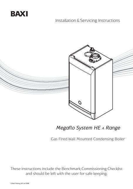
1.0 Introduction1.1 DescriptionCase Front Panel1. The <strong>Baxi</strong> <strong>Megaflo</strong> <strong>System</strong> <strong>HE</strong> A is a fully automatic gas firedwall mounted <strong>co</strong>ndensing system boiler. It is room sealed andfan assisted.2. The boiler is set to give a maximum output of :-<strong>15</strong> models - <strong>15</strong> kW16.2 kW (Condensing)<strong>18</strong> models - <strong>18</strong> kW19.4 kW (Condensing)<strong>24</strong> models - <strong>24</strong> kW25.9 kW (Condensing)<strong>28</strong> models - <strong>28</strong> kW30.3 kW (Condensing)<strong>32</strong> models - <strong>32</strong> kW34.4 kW (Condensing)3. It is designed for use on Natural Gas (G20).4. The boiler in<strong>co</strong>rporates a circulating pump and expansionvessel. It is suitable for use only on fully pumped sealedsystems.Control Box5. The boiler data badge gives details of the model, serialnumber and Gas Council number and is situated on the innerdoor panel. It is visible when the case front panel is removed(Fig. 1).Fig. 1Data BadgeInformation Label6. The boiler model name and serial number are also shownon the information label on the rear of the lower door panel.This is for user reference.7. The boiler is intended to be installed in residential /<strong>co</strong>mmercial / light industrial E.M.C. environments on agoverned meter supply only.8. The boiler must be installed with one of the purposedesigned flues such as the standard horizontal teles<strong>co</strong>pic fluekit, part no. 51<strong>18</strong>069.9. All systems must be thoroughly flushed and treated withinhibitor (see section 6.1).1.2 Contents of PackThe pack <strong>co</strong>ntains:-• Boiler• Wall Plate (including taps)• Set of Pipe Connections• Template & ‘Quick Fit’ Guide• Literature Pack© <strong>Baxi</strong> Heating UK Ltd 20087
2.0 General Layout2.1 Layout221. Expansion Vessel121142. Automatic Air Vent3. Circulation Pump4. Drain Off Point135. Pressure Relief Valve6. Selector Switch7. Central Heating <strong>System</strong> Pressure Gauge8. PCB9. Control Box201210. Gas Valve11. Condensate Trap12. Flame Sensing Electrode<strong>15</strong>13. Spark Electrode14. Primary Heat Exchanger619<strong>15</strong>. Fan Assembly16. On/Off/Reset Selector Switch17. Central Heating Temperature Control<strong>18</strong>. Calibration Control19. Venturi98720. Air/Gas Collector21. Combustion Box Cover & Burner22. Igniter23. Burner On Light11<strong>24</strong>. Central Heating Mode Light25. Display210354<strong>24</strong>1230bar4816 2523 17 <strong>18</strong> 7© <strong>Baxi</strong> Heating UK Ltd 2008
3.0 Appliance OperationBoiler Primary Circuit13.1 Operating Mode (Fig. 2)1. With a demand for heating or hot water, the pumpcirculates water through the primary circuit. If the pressure isat least 0.5 bar the ignition sequence will start.<strong>18</strong>20342192. When the flow temperature exceeds the settingtemperature, a 3 minute delay occurs before the burnerrelights automatically (anti-cycling). The pump <strong>co</strong>ntinues torun during this period.3. When the demand is satisfied the burner is extinguishedand the pump <strong>co</strong>ntinues to run for a period of 3 minutes(Pump Overrun).576IMPORTANT: When the selector switch is in the ‘0’(Off) position the electrical supply to the boiler isisolated. The boiler will not operate.<strong>15</strong>17161413983.2 Frost Protection Mode1. The frost protection mode is integral to the appliance andfunctions when the selector switch (see Section 2.1) is in theON position ( ). If the system temperature falls below5° C then the boiler will fire on its minimum setting until aflow temperature of 30° C is reached. Further protectioncan be in<strong>co</strong>rporated by using a system frost thermostat.3.3 Pump Protection1110 121. With the selector switch (see Section 2.1) in the ONposition ( ) the pump will automatically operate for 1minute in every <strong>24</strong> hours to prevent sticking.KeyFig. 21 Heat Exchanger2 Burner3 Ignition Electrode4 Flame Sensing Electrode5 Gas Valve6 Pump7 Automatic Air Vent8 Pressure Relief Valve9 Boiler Drain Point10 Gas Inlet11 Boiler Flow12 Boiler Return13 Pressure Gauge14 Automatic By-Pass<strong>15</strong> Water Pressure Sensor16 Safety Thermostat17 Temperature Sensor<strong>18</strong> Expansion Vessel19 Return Temperature Sensor20 Fan© <strong>Baxi</strong> Heating UK Ltd 20089
4.0 Technical Data4.1 <strong>Megaflo</strong> <strong>System</strong> <strong>15</strong>, <strong>18</strong>, <strong>24</strong>, <strong>28</strong> & <strong>32</strong> <strong>HE</strong> AAppliance Type C 13 C 33 C 53 Inlet Pressure (Natural Gas - G20)mbar 20Appliance Category CAT I 2HHeat Input (Net) Max Min<strong>15</strong> model kW <strong>15</strong>.4 4<strong>18</strong> model kW <strong>18</strong>.5 4.3<strong>24</strong> model kW <strong>24</strong>.7 7<strong>28</strong> model kW <strong>28</strong>.9 9.7<strong>32</strong> model kW <strong>32</strong>.8 9.7Heat Input (Gross) Max Min<strong>15</strong> model kW 17.1 4.4<strong>18</strong> model kW 20.5 4.8<strong>24</strong> model kW 27.4 7.8<strong>28</strong> model kW <strong>32</strong>.1 10.8<strong>32</strong> model kW 36.4 10.8Heat Output (Non-Condensing)Max Min<strong>15</strong> model kW <strong>15</strong> 3.9<strong>18</strong> model kW <strong>18</strong> 4.2<strong>24</strong> model kW <strong>24</strong> 6.8<strong>28</strong> model kW <strong>28</strong> 9.4<strong>32</strong> model kW <strong>32</strong> 9.4Heat Output (Condensing)Max Min<strong>15</strong> model kW 16.2 4.2<strong>18</strong> model kW 19.4 4.5<strong>24</strong> model kW 25.9 7.4<strong>28</strong> model kW 30.3 10.2<strong>32</strong> model kW 34.4 10.2Max Gas Rate (Natural Gas - G20)(After 10 mins)<strong>15</strong> model m 3 /h 1.69<strong>18</strong> model m 3 /h 1.95<strong>24</strong> model m 3 /h 2.61<strong>28</strong> model m 3 /h 3.1<strong>32</strong> model m 3 /h 3.48Electrical Supply230V~ 50H z(Appliance must be <strong>co</strong>nnected to anearthed supply)Power Consumption<strong>15</strong> model 130W<strong>18</strong> model 140W<strong>24</strong> model <strong>15</strong>0W<strong>28</strong> & <strong>32</strong> models 160WElectrical ProtectionIPX5DExternal Fuse RatingInternal Fuse Rating F2LCondensate DrainTo accept 21.5mm ( 3 /4 in) plastic waste pipeFlue Terminal Diameter 100mmDimensions Projection 125mmConnections<strong>co</strong>pper tailsGas Supply - 22mmCentral Heating Flow - 22mmCentral Heating Return - 22mmPressure Relief Discharge - <strong>15</strong>mmOutercase DimensionsCasing HeightOverall Height Inc Flue ElbowCasing WidthCasing DepthClearancesAbove CasingBelow CasingFrontFrontL.H. SideR.H. Side3A- 780mm- 965mm- 450mm- 345mm200 mm Min200 mm Min450 mm Min (For Servicing)5 mm Min (In Operation)5 mm Min5 mm Min (In Operation)NO x Class 5Central Heating Primary CircuitPressuresbarSafety Discharge 3Max Operating 2.5Min Operating 0.5Re<strong>co</strong>mmended Operating Range 1-2PumpAvailable HeadSee graph belowExpansion Vessel - (Integral with appliance)barMin Pre-charge Pressure 0.5litreMax Capacity ofCH <strong>System</strong> 125Primary Water Contentof Boiler (unpressurised) 2.5TemperaturesFlow Temp (adjustable)25°C to 80°C max (± 5°C)Weights<strong>15</strong> & <strong>18</strong> <strong>24</strong>Packaged Boiler Carton 43.6kg 44.2kgInstallation Lift Weight 38.6kg 39.2kgPackaged Boiler CartonInstallation Lift Weight<strong>28</strong> & 3<strong>24</strong>6kg41kgInjector (Natural Gas - G20)<strong>15</strong> model 4.5mm<strong>18</strong> model 5.7mm<strong>24</strong> model 7.5mm5.5Pump - Available Head<strong>28</strong> model 12mm5<strong>32</strong> model 12mm4.5SEDBUK DeclarationThe seasonal efficiency (SEDBUK) for all models is:-91.2% Band AThis value is used in the UK Government’s Standard Assessment Procedure(SAP) for energy rating of dwellings. The test data from which it has beencalculated have been certified by 0087.Metre (wg)43.5<strong>32</strong>.521.510.510 © <strong>Baxi</strong> Heating UK Ltd 200800200 400 600 800 1000 1200Flow Rate (l/h)
5.0 Dimensions and FixingsDimensionsAt least 1.5°GEAB780mm345mmC 450mmAD 116mm Ø Min.EF<strong>18</strong>5mm(207mm for 80/125mmflue systems)145mmB360° OrientationG 131mmH <strong>18</strong>0mmDCHTube Ø 100mmFTap Rail<strong>32</strong>.5 mmCondensateDrain130 mm 130 mm 65 mmHeatingFlow(22mm)GasInlet(22mm)HeatingReturn(22mm)Pressure ReliefValve(<strong>15</strong>mm)© <strong>Baxi</strong> Heating UK Ltd 200811
6.0 <strong>System</strong> Details6.1 Central Heating Circuit1. The appliance is suitable for fully pumped SEALED SYSTEMSONLY.Treatment of Water Circulating <strong>System</strong>s• All recirculatory water systems will be subject to<strong>co</strong>rrosion unless an appropriate water treatment isapplied. This means that the efficiency of the system willdeteriorate as <strong>co</strong>rrosion sludge accumulates within the system,risking damage to pump and valves, boiler noise and circulationproblems.• When fitting new systems flux will be evident within the system,which can lead to damage of system <strong>co</strong>mponents.• All systems must be thoroughly drained and flushed out. Using,for example Betz-Dearborn Sentinel X300 or X400 or FernoxSuperfloc Universal Cleanser. They should be used following theflushing agent manufacturer’s instructions.• <strong>System</strong> additives - <strong>co</strong>rrosion inhibitors and flushingagents/descalers should <strong>co</strong>mply to BS7593 requirements, e.g.Betz-Dearborn Sentinel X100 and Fernox-Copal which should beused following the inhibitor manufacturer’s instructions.Failure to flush and add inhibitor to the system willinvalidate the appliance warranty.• It is important to check the inhibitor <strong>co</strong>ncentration afterinstallation, system modification and at every service inac<strong>co</strong>rdance with the manufacturer’s instructions. (Test kits areavailable from inhibitor stockists.)• For information or advice regarding any of the above <strong>co</strong>ntactTechnical Enquiries.6.2 Bypass1. The boiler is fitted with an automatic integral bypass.6.3 <strong>System</strong> Control1. For optimum operating <strong>co</strong>nditions, the heating system intowhich the boiler is installed should include a <strong>co</strong>ntrol system.2. Such a system will <strong>co</strong>mprise of a timer <strong>co</strong>ntrol and separateroom or cylinder thermostats as appropriate.3. The boiler should be <strong>co</strong>ntrolled so that it operates ondemand only.4. Operation of the system under <strong>co</strong>ntrol of the boilerthermostat & TRV’s only does not produce the best results.12© <strong>Baxi</strong> Heating UK Ltd 2008
6.0 <strong>System</strong> Details6.4 <strong>System</strong> Filling and Pressurising1. A filling point <strong>co</strong>nnection on the central heating returnpipework must be provided to facilitate initial filling andpressurising and also any subsequent water lossreplacement/refilling.Fig. 3StopValveMainsColdWaterDoubleCheckValveTemporaryHoseStopValveCHReturn2. The filling method adopted must be in ac<strong>co</strong>rdance with allrelevant water supply regulations and use approvedequipment.3. Your attention is drawn to:for GB: Guidance G<strong>24</strong>.2 and re<strong>co</strong>mmendation R<strong>24</strong>.2 of theWater Regulations Guide.for IE: the current edition of I.S. 813 “Domestic GasInstallations”.4. The sealed primary circuits may be filled or replenished bymeans of a temporary <strong>co</strong>nnection between the circuit and asupply pipe, provided a ‘Listed’ double check valve or someother no less effective backflow prevention device ispermanently <strong>co</strong>nnected at the inlet to the circuit and thetemporary <strong>co</strong>nnection is removed after use.6.5 Expansion Vessel1. The appliance expansion vessel is pre-charged to 0.5 bar.Therefore, the minimum <strong>co</strong>ld fill pressure is 0.5 bar. Thevessel is suitable for <strong>co</strong>rrect operation for system capacities upto 125 litres. For greater system capacities an additionalexpansion vessel must be fitted. For GB refer to BS 7074 Pt 1.For IE, the current edition of I.S. 813 “Domestic GasInstallations”.6.6 Pressure Relief Valve (Fig. 4)1. The pressure relief valve is set at 3 bar, therefore allpipework, fittings, etc. should be suitable for pressures inexcess of 3 bar and temperature in excess of 100°C.2. The pressure relief discharge pipe should be not less than<strong>15</strong>mm dia, run <strong>co</strong>ntinuously downward, and discharge outsidethe building, preferably over a drain. It should be routed insuch a manner that no hazard occurs to occupants or causesdamage to wiring or electrical <strong>co</strong>mponents. The end of thepipe should terminate facing down and towards the wall.Fig. 43. The discharge must not be above a window, entrance orother public access. Consideration must be given to thepossibility that boiling water/steam <strong>co</strong>uld discharge from thepipe.Pressure Relief ValveDischarge Pipe4. A remote relief valve kit is available to enable the boiler tobe installed in cellars or similar locations below outsideground level (kit no. 5121379).© <strong>Baxi</strong> Heating UK Ltd 200813
7.0 Site Requirements5mm Min450mm5mm Min7.1 Location200mm Min(300mm Min ifusing 80/125mmflueing system)1. The boiler may be fitted to any suitable wall with the fluepassing through an outside wall or roof and discharging toatmosphere in a position permitting satisfactory removal of<strong>co</strong>mbustion products and providing an adequate air supply.The boiler should be fitted within the building unlessotherwise protected by a suitable enclosure i.e. garage orouthouse. (The boiler may be fitted inside a cupboard-seeSection 7.3).2. If the boiler is sited in an unheated enclosure then it isre<strong>co</strong>mmended to leave the ON/OFF Selector Switch in theOn position.780mm3. If the boiler is fitted in a room <strong>co</strong>ntaining a bath or showerreference must be made to the relevant requirements.In GB this is the current I.E.E. Wiring Regulations and BuildingRegulations.In IE reference should be made to the current edition of I.S.813 “Domestic Gas Installations” and the current ETCI rules.Fig. 5200mm Min4. If the boiler is to be fitted into a building of timber frame<strong>co</strong>nstruction then reference must be made to the currentedition of Institute of Gas Engineers Publication IGE/UP/7(Gas Installations in Timber Framed Housing).7.2 Clearances (Figs. 5 & 6)At least 1.5°1. A flat vertical area is required for the installation of theboiler.2. These dimensions include the necessary clearances aroundthe boiler for case removal, spanner access and airmovement. Additional clearances may be required for thepassage of pipes around local obstructions such as joistsrunning parallel to the front face of the boiler.450mm MinFor ServicingPurposes5mm MinFig. 6In Operation14© <strong>Baxi</strong> Heating UK Ltd 2008
7.0 Site RequirementGas Service Cock7.3 Ventilation of Compartments1. Where the appliance is installed in a cupboard or<strong>co</strong>mpartment, no air vents are required.2. BS 5440: Part 2 refers to room sealed appliancesinstalled in <strong>co</strong>mpartments. The appliance will run sufficiently<strong>co</strong>ol without ventilation.7.4 Gas Supply1. The gas installation should be in ac<strong>co</strong>rdance with therelevant standards. In GB this is BS 6891. In IE this is thecurrent edition of I.S. 813 “Domestic Gas Installations”.Fig. 72. The <strong>co</strong>nnection to the appliance is a 22mm <strong>co</strong>pper taillocated at the rear of the gas service <strong>co</strong>ck (Fig. 7).Zone 1Zone 0Zone 2WindowRecessZone 2Zone 30.6 m 2.4 m3. Ensure that the pipework from the meter to theappliance is of adequate size, and the demands of anyother gas appliances in the property are taken into<strong>co</strong>nsideration. Do not use pipes of a smaller diameter thanthe boiler gas <strong>co</strong>nnection (22mm).7.5 Electrical Supply1. External wiring must be <strong>co</strong>rrectly earthed, polarised andin ac<strong>co</strong>rdance with relevant regulations/rules. In GB this isthe current I.E.E. Wiring Regulations. In IE reference shouldbe made to the current edition of ETCI rules.WindowRecessZone 2Zone <strong>32</strong>. The mains supply is 230V ~ 50H z fused at 3A.NOTE: The method of <strong>co</strong>nnection to the electricitysupply must facilitate <strong>co</strong>mplete electrical isolation ofthe appliance.Fig. AIn GB OnlyConnection may be via a fused double-pole isolatorwith a <strong>co</strong>ntact separation of at least 3mm in all polesand servicing the boiler and system <strong>co</strong>ntrols only.Zone 2Zone 3Outside ZonesCeiling3. When the system includes an indirect domestic hotwater cylinder it is re<strong>co</strong>mmended that a cylinderthermostat is used in <strong>co</strong>njunction with a 3 port 2 positionvalve or 2 port zone valve.WindowRecessZone 23.0 mZone 1 Zone 2Zone 00.6 mFig. B In GB Only© <strong>Baxi</strong> Heating UK Ltd 2008Zone <strong>32</strong>.4 m2.25 mOutsideZones7.6 Bath & Shower Rooms1. If the boiler is fitted in a room <strong>co</strong>ntaining a bath orshower and NOT FITTED with any optional integral timeror thermostat, it can be fitted in zone 2, (Figs. A & B showszone dimensions for a bathtub. For other examples refer toSection 601 of the Current I.E.E. Wiring Regulations)reference must be made to the relevant requirements.In GB this is the current I.E.E. Wiring Regulations andBuilding Regulations.In IE reference should be made to the current edition of I.S.813 “Domestic Gas Installations” and the current ETCIrules.<strong>15</strong>
7.0 Site RequirementsSinkBoiler50mm per metre of pipe run2.5° Minimum fall450mm minBoilerTermination to an internal soil andvent pipe50mm per metre of pipe run2.5° Minimum fallExternal termination via internal dischargebranche.g sink waste - downstreamPipe must terminateabove water level butbelow surroundingsurface7.7 Condensate DrainFAILURE TO INSTALL T<strong>HE</strong> CONDENSATE DISCHARGEPIPEWORK CORRECTLY WILL AFFECT T<strong>HE</strong> RELIABLEOPERATION OF T<strong>HE</strong> BOILERThe <strong>co</strong>ndensate discharge pipe MUST NOT RISE at any pointalong its length. There MUST be a fall of AT LEAST 2.5°(50mm per metre) along the entire run.1. The <strong>co</strong>ndensate outlet will accept 21.5mm ( 3 /4in) plasti<strong>co</strong>verflow pipe which should generally discharge internally intothe household drainage system. If this is not possible, dischargeinto an outside drain is acceptable.2. Ensure the discharge of <strong>co</strong>ndensate <strong>co</strong>mplies with anynational or local regulations in force.BS 6798:2000 & Part H1 of the Building Regulations givefurther guidance.3. The discharge pipe should be run in a proprietary drain pipematerial e.g. PVC, PVC-U, ABS, PVC-C or PP.4. Metal pipework is NOT suitable for use in <strong>co</strong>ndensatedischarge systems.5. The pipe should be a minimum of 21.5mm diameter andmust be supported using suitably spaced clips to preventsagging.6. It is advisable to keep the <strong>co</strong>ndensate pipe internal.7. External runs greater than 3 metres or runs in <strong>co</strong>ld areasshould use <strong>32</strong>mm waste pipe.BoilerTermination to a drain or gullyPipe must terminate abovewater level but belowsurrounding surface8. If the boiler is fitted in an unheated location the entire<strong>co</strong>ndensate discharge pipe should be treated as an externalrun.9. In all cases discharge pipe must be installed to aid disposalof the <strong>co</strong>ndensate. To reduce the risk of <strong>co</strong>ndensate beingtrapped, as few bends and fittings as possible should be used.Boiler50mm per metre of pipe run2.5° Minimum fallTermination to a purpose made soakaway500mm min10. When discharging <strong>co</strong>ndensate into a soil stack or wastepipe the effects of existing plumbing must be <strong>co</strong>nsidered. If soilpipes or waste pipes are subjected to internal pressurefluctuations when WC's are flushed or sinks emptied thenback-pressure may force water out of the boiler trap andcause appliance lockout.Examples are shown of the following methods of termination:-i) to an internal soil & vent pipeii) via an internal discharge branch (e.g. sink waste)iii) to a drain or gullyiv) to a purpose made soakaway50mm per metre of pipe run2.5° Minimum fallHoles in the soak-away mustface away from the building16© <strong>Baxi</strong> Heating UK Ltd 2008
Terminal Position with Minimum Distance (Fig. 9)TerminalAssembly300 min(mm)A a Directly below an opening, air brick, openingwindows, etc. 300B a Above an opening, air brick, opening window etc. 300C a Horizontally to an opening, air brick, opening window etc. 300D Below gutters, soil pipes or drain pipes. 25E Below eaves. 25F Below bal<strong>co</strong>nies or car port roof. 25G From a vertical drain pipe or soil pipe. 25H From an internal or external <strong>co</strong>rner. 25I Above ground, roof or bal<strong>co</strong>ny level. 300J From a surface or boundary line facing a terminal. 600K From a terminal facing a terminal (Horizontal flue). 1200From a terminal facing a terminal (Vertical flue). 600L From an opening in carport (e.g. door, window)into the dwelling. 1200M Vertically from a terminal on the same wall. <strong>15</strong>00N Horizontally from a terminal on the same wall. 300R From adjacent wall to flue (vertical only). 300S From an adjacent opening window (vertical only). 1000T Adjacent to windows or opening on pitched and flat roofs. 600U Below windows or openings on pitched roofs. 2000a In addition, the terminal should be no nearer than <strong>15</strong>0 mm to anopening in the building fabric formed for the purpose of ac<strong>co</strong>mmodatinga built-in element such as a window frame. See BS 5440 Pt. 1.NOTE: The distance from a fanned draught appliance terminalinstalled parallel to a boundary may not be less than 300mm inac<strong>co</strong>rdance with the diagram below*7.0 Site Requirements7.8 FlueNOTE: Due to the nature of the boiler a plume of watervapour will be discharged from the flue. This should betaken into ac<strong>co</strong>unt when siting the flue terminal.1. The following guidelines indicate the general requirementsfor siting balanced flue terminals. For GB re<strong>co</strong>mmendationsare given in BS 5440 Pt 1. For IE re<strong>co</strong>mmendations are givenin the current edition of I.S. 813 “Domestic GasInstallations”.2. If the terminal discharges onto a pathway or passageway,check that <strong>co</strong>mbustion products will not cause a nuisanceand that the terminal will not obstruct the passageway.3. If a terminal is less than 2 metres above a bal<strong>co</strong>ny, aboveground or above a flat roof to which people have access,then a suitable terminal guard must be provided.IMPORTANT:• Only ONE 25mm clearance is allowed per installation.• Under car ports we re<strong>co</strong>mmend the use of the plumedisplacement kit.• The terminal position must ensure the safe andnuisance - free dispersal of <strong>co</strong>mbustion products.Fig. 8Top View Rear FlueProperty Boundary LinePlumeDisplacement KitIMPORTANT: If fitting a PlumeDisplacement Flue Kit, the air inletmust be a minimum of 100mm fromany opening windows or doors (seeSection 9.0).J,KTUAir InletOpening Windowor DoorRMNCDEA100mmMIN.Fig. 10IIISIFLGAIBHA F HJ,KLikely flue positions requiringa flue terminal guardFig. 9© <strong>Baxi</strong> Heating UK Ltd 200817
8.0 Flue Options8.1 Horizontal Flue <strong>System</strong>sY1. The standard flue is suitable only for horizontaltermination applications.X2. All fittings should be fully engaged. The approximateengagement is 40mm. Apply soap solution to the seal oneach fitting to aid assembly.3. Maximum permissible equivalent flue lengths are:-HorizontalFluesHorizontal Concentric (<strong>15</strong>/<strong>18</strong> models)Horizontal Concentric (<strong>24</strong>/<strong>28</strong>/<strong>32</strong> models)Horizontal Concentric (all)(60/100)<strong>15</strong> metres(60/100)10 metres(80/125)20 metresPlume Displacement 60 /100 dia Kit1M Extensions 45° & 93° elbowsare also available - see Section 9.0Plume Displacement.4. Any additional “in line” bends in the flue system must betaken into <strong>co</strong>nsideration.Their equivalent lengths are:-Concentric Pipes:135° bend 0.5 metres93° bend 1.0 metresTwin Flue Pipe135° bend 0.25 metres91.5° bend 0.50 metresThe elbow supplied with the standard horizontal teles<strong>co</strong>picflue kit is not included in any equivalent length calculationsNOTE: Flue length is measured from point X to Y asshown.NOTE: Horizontal flue pipes should always be installed with a fall of at least 1.5°from the terminal to allow <strong>co</strong>ndensate to run back to the boiler.This bend is equivalent to1 metreACBYXThis bend is equivalent to1 metreTotal equivalent length =A+B+C+2x90°Bends<strong>18</strong>© <strong>Baxi</strong> Heating UK Ltd 2008
8.0 Flue OptionsVerticalFluesVerticalFlues(Twin Pipe)Yx8.2 Twin & Vertical Flue <strong>System</strong>s1. Maximum permissible equivalent flue lengths are:-(60/100) (80/125)Vertical Concentric 10 metres 20 metresVertical Twin Pipe <strong>15</strong> metres2. Any additional “in line” bends in the flue system must betaken into <strong>co</strong>nsideration.Their equivalent lengths are:-Concentric Pipes:135° bend 0.5 metres93° bend 1.0 metresTwin Flue Pipe135° bend 0.25 metres91.5° bend 0.50 metresThe elbow supplied with the standard horizontal teles<strong>co</strong>picflue kit is not included in any equivalent length calculationsNOTE: Flue length is measured from point X to Y asshown.YXTotal Equivalent Length =A+B+C+1x90°BendAll vertical and angled runs must be included,measured from the boiler adaptor (point X) to thejoint with the flue terminal (point Y). One 91.5°bend or two 135° bends can be included withoutreduction of the flue length.RoofTerminalIf further elbows are required the flue length mustbe reduced by the following amounts:-1 metre for each 91.5° bend0.5 metre for each 45° bendAXBYC660mmThis bend is equivalent to1 metreThe total equivalent length for this example is= 6.5 metres.1m extension135°bend91.5°bend1m extension135°bend91.5°bendEquivalentLength Value1m0.25m0.5mAIR DUCTN o offittings/pipes522Sub total5.0m0.5m1.0mEquivalent Length Air Duct = 6.5mEquivalentLength Value1m0.25m0.5mFLUE DUCTN o offittings/pipes522Sub total5.0m0.5m1.0mEquivalent Length Flue Duct = 6.5m© <strong>Baxi</strong> Heating UK Ltd 200819
8.0 Flue OptionsA48.3 Flue AccessoriesA3A2BEAPKey Accessory Size Code NoFLUE GROUP AConcentric Flue <strong>System</strong> 100mm diameterA3 Teles<strong>co</strong>pic Internal Flue Kit 3<strong>15</strong>-500mm 5119654A2 Teles<strong>co</strong>pic Flue (incl elbow) 51<strong>18</strong>069A Horizontal Flue Terminal (incl elbow) 51<strong>18</strong>489B Flue Extension 1000mm 5111074C Flue Bend 93° 5111075D Flue Bend (pair) 135° 5111085U Pipe Support (painted) 100mmØ 5111080R Vertical Flue Adaptor 5111070P Wall Liner 5111067S Flue Terminal Deflector 5111068K,K1FLUE GROUP NTwin Flue <strong>System</strong> 80mm diameterE Flue Extension (pair) 1000mm 5111087F Flue Bend (pair) 90° 5111072G Flue Bend (2 pair) 135° 5111086J Vertical Flue Boiler Adaptor Kit 5111079H Vertical Flue Adaptor 5111084W Pipe Support (pair) 80mm 5111081CDRFLUE GROUP GFlue <strong>System</strong> 80/125mm diameterA4 Horizontal Flue Kit 51<strong>18</strong>580B Straight Extension Kit 1000mm 51<strong>18</strong>584D Bend Kit (pair) 135° 51<strong>18</strong>597C Bend 91.5° 51<strong>18</strong>588GFHMFLUE GROUP A, N, GVertical Flue KitsK Vertical Flue Terminal (use with 5111070) 5111078K1 Vertical Flue Terminal 51<strong>18</strong>576L Pitch Roof Flashing 25°/50° 5122<strong>15</strong>1M Roof Cover Plate <strong>24</strong>6143N Flat Roof Flashing <strong>24</strong>6144U,WNLSJ20© <strong>Baxi</strong> Heating UK Ltd 2008
8.0 Flue OptionsFor Twin Flue <strong>System</strong>s fit the adaptors as follows:-Blanking PlateFlue Duct Adaptor8.4 Flue Duct Adaptor1. Engage the flue adaptor on the boiler adaptor, making surethat it is pushed down as far as possible.Boiler Adaptor8.5 Air duct adaptor1. Undo the screws securing the blanking plate to the boilertop panel. Discard the plate.2. There are three restrictor plates supplied in the kit. Onemarked ‘23’ can be discarded. The one marked ‘27’ must beused on the <strong>15</strong>/<strong>18</strong> kW (models). The third restrictor is for allother models in the range. The restrictors MUST bepositioned as shown in the diagrams below.3. Take one of the gaskets supplied in the kit and place onthe boiler top panel.4. Align the appropriate restrictor as shown. Position these<strong>co</strong>nd gasket over the restrictor.5. Using the screws previously removed secure the inletadaptor to the top panel.6. Continue to fit the twin flue system.Air Duct AdaptorPosition of RestrictorGasketRestrictorGasket<strong>15</strong>/<strong>18</strong> kW models<strong>24</strong> kW models<strong>28</strong>/<strong>32</strong> kW models© <strong>Baxi</strong> Heating UK Ltd 200821
8.0 Flue Options8.6 For Roof TerminalsApprox1425mm1. In the case of a pitched roof 25 - 50 degrees, position the leadtile to replace/flash over existing roof tiling. Make an aperture inthe roof suitable for the lower tube of the roof terminal andensure the integrity of the roof <strong>co</strong>ver is maintained. Theadjustable plastic <strong>co</strong>llar can either be positioned on the lead tileor the lower tube of the roof terminal prior to the finalpositioning of the vertical flue through the tile. Check the <strong>co</strong>llar is<strong>co</strong>rrectly located to suit required roof pitch (either 25° to 38° or37° to 50°). From inside the roof adjust the flue to a verticalposition and secure to the roof structure with the clamp supplied.Cut the sameamount off theAir Duct &Flue DuctAir DuctFlue Duct2. For flat roof installations the aluminium flashing must bein<strong>co</strong>rporated into the roof <strong>co</strong>vering and the appropriate aperturemade in the roof decking. The vertical flue is lowered onto theflashing making sure the <strong>co</strong>llar of the flue locates securely with theflashing. (A mastic seal may be necessary). From inside the roof,adjust the flue to a vertical position and secure to the roofstructure with the clamp supplied.Push Fit AdaptorIMPORTANT: If the boiler is not fitted immediately after the fluesystem, temporary precautions must be taken to prevent rainentry into the room of installation. Any precautionary measuresmust be removed prior to <strong>co</strong>mmissioning the boiler.8.7 Flue DimensionsThe standard horizontal teles<strong>co</strong>pic flue kit allows for lengthsbetween 3<strong>15</strong>mm and 500mm from elbow to terminal (Fig. 11).3<strong>15</strong>mm 500mmThe maximum permissible equivalent horizontal flue length is:10 metres (60/100 system, <strong>24</strong>/<strong>28</strong>/<strong>32</strong> models)<strong>15</strong> metres (60/100 system, <strong>15</strong>/<strong>18</strong> models)20 metres (80/125 system, all models)Fig. 11Flue Deflector8.8 Flue Trim1. The rubber flue trim supplied may be fitted to either theoutside wall or on the inner wall of installation.8.9 Terminal Guard (Fig. 12)1. When <strong>co</strong>des of practice dictate the use of terminal guards, theycan be obtained from most Plumbers’ and Builders’ Merchants.2. There must be a clearance of at least 50mm between any partof the terminal and the guard.3. When ordering a terminal guard, quote the appliance nameand model number.4. The flue terminal guard should be positioned centrally over theterminal and fixed as illustrated.22Fig. 12© <strong>Baxi</strong> Heating UK Ltd 20088.10 Flue Deflector1. If required, push the flue deflector over the teminal end androtate to the optimum angle for deflecting plume. Secure thedeflector to the terminal with screws provided.
93° Elbow/PlumeOutlet Assembly9.0 Plume DisplacementO Ring60Ø SupportBracket9.1 Plume Displacement Kit (Fig. 14)Fig. 130.9 metresO RingAdaptorO Ring60Ø ExhaustFlue Pipe60Ø SupportBracketFlexible FlueTrim‘Jubilee’ ClipKit No 51<strong>18</strong>638Content of kit1 0.9m 60/100 Concentric Flue1 1m 60 Dia Exhaust Flue Pipe1 Adaptor2 60 Dia Support Brackets1 93° Elbow/Plume Outlet Assembly1 Flexible Flue Trim3 “O” Rings1 ‘Jubilee Clip1 Elbow1. This kit is re<strong>co</strong>mmended for installations where the<strong>co</strong>ndensate plume emitted from the flue may cause a nuisanceor affect the surroundings.2. The terminal must be positioned outside the building withthe air inlet facing downward and outlet <strong>co</strong>nnection upwards.60/100ØConcentric FlueFig. 14Elbow3. The plume outlet must always be at least 45° to the wall,with the ‘peak’ uppermost to prevent rain entry (Figs. <strong>15</strong> &16), and be at least 2 metres above ground level. It must besecured as shown in Fig. 10. The plume outlet must also be atleast 500mm from the air inlet in any direction (Fig. 16).45°45°Outlet must be atleast 45° fromwall face‘Peak’ UppermostNOTE: The outlet must be positioned so that any<strong>co</strong>ndensate plume is directed away from adjacent surfaces.There must be a <strong>co</strong>nstant fall along the entire length of theflue system from the outlet back to the boiler.4. It is possible to reduce or increase (with the addition ofextensions) the length of either or both the 60/100 <strong>co</strong>ncentricand 60Ø exhaust.5. Standard <strong>co</strong>ncentric flue extension kits may be addedbetween the boiler elbow and the terminal assembly.500mm Min.6. The minimum length of the <strong>co</strong>ncentric flue is 100mm whenmeasured from the edge of the flue elbow.Fig. <strong>15</strong>Air Inlet at BottomIMPORTANT: The maximum equivalent length of<strong>co</strong>ncentric flue is:- 8 metres (<strong>24</strong>/<strong>28</strong>/<strong>32</strong>)14 metres (<strong>15</strong>/<strong>18</strong>)Additional bends may be fitted in the <strong>co</strong>ncentric flue, butthe equivalent length must be reduced by 1 metre (93°elbow) or 0.5 metres (45° elbow).Fig. 167. 60Ø 1 metre extensions (including support bracket), andadditional 93° & 45° elbows are available. Any additional 93°& 45° elbows must be ac<strong>co</strong>unted for when calculating fluelengths.NOTE: Permitted positions of the plume outlet relative todoors, windows etc. are the same as for <strong>co</strong>nventional<strong>co</strong>ncentric flues as detailed in the main Installation &Servicing Instructions and BS5440 Pt. 1. It is NOTnecessary to fit a terminal guard over the air inlet or theplume outlet.© <strong>Baxi</strong> Heating UK Ltd 200823
9.0 Plume Displacement9.2 Determining Permissible Lengths161660 Ø Exhaust (metres) X1412108642<strong>15</strong>/<strong>18</strong><strong>24</strong><strong>28</strong>/<strong>32</strong>60 Ø Exhaust (metres) X1412108642<strong>15</strong>/<strong>18</strong><strong>24</strong><strong>28</strong>/<strong>32</strong>In the graph the solid line diagonal represents therelationship between the <strong>co</strong>ncentric flue assembly (and anyextensions) and the 60Ø exhaust (and any extensions oradditional bends).002 1 3 4 6 5 7 9 8 10 12 1411 13 <strong>15</strong>Concentric 60/100 Flue (metres) YExample 1Flue Lengths - Not Permissible00 2 1 3 4 6 5 7 9 8 10 12 1411 13 <strong>15</strong>Concentric 60/100 Flue (metres) YExample 2Flue Lengths - OKExample 1 - Not PermissibleIf, for instance, a <strong>co</strong>ncentric length of 5 metres was requiredand the 60Ø exhaust needed to be 6 metres the graphshows that this <strong>co</strong>mbination would NOT be permissible asthe intersection point would be above the solid diagonal line.60 Ø Exhaust (metres) X16141210864200<strong>15</strong>/<strong>18</strong><strong>24</strong><strong>28</strong>/<strong>32</strong>1 2 3 4 5 6 7 8 9 10 11 12 13 14 <strong>15</strong>Concentric 60/100 Flue (metres) YExample 3Flue Lengths - OKExample 2 - Flue Lengths OKWhere both lengths have been determined they can beapplied to the graph to check that the installation ispermissible. For example, if it was known that 2 metres of<strong>co</strong>ncentric flue and 4 metres of 60Ø exhaust were required,the values <strong>co</strong>uld be applied to the graph as shown inExample 2. As the point of intersection of the dotted lines isbelow the solid diagonal line, the <strong>co</strong>mbination of lengths isshown to be acceptable.Example 3 - Flue Lengths OKIn the example shown, assume that the <strong>co</strong>ncentric part ofthe flue needs to be 2.3 metres long. Find the position of‘2.3’ on the horizontal axis of the graph and then projectupwards to the solid diagonal line. This is represented by thevertical thick dotted line. Where this dotted line intersectswith the solid diagonal line on the graph, project across tothe vertical axis. As can be seen this <strong>co</strong>rresponds with 6metres. Therefore, the total equivalent length of the 60Øexhaust can be up to 6 metres. Any elbow equivalenciesmust be ac<strong>co</strong>unted for i.e. 93° elbows are equal to 1 metre,each 45° elbow to 0.5 metres.60Ø ExhaustSupportBracketYX45° ElbowFlue Length - Worked Example<strong>Baxi</strong> <strong>Megaflo</strong> <strong>System</strong> <strong>28</strong> <strong>HE</strong> AConcentric 60/100 Flue93° Elbow1 metre ExtensionIn Fig. <strong>18</strong> opposite an additional 93° elbow and pair of 45°elbows have been included in the 60Ø exhaust.Also 3 straight extension pieces have been used.Fig. 171 metre supplied in kitTo calculate total length:-Length of 60Ø supplied in kit = 1 metre3 x 1 metre Extensions = 3 metres1 x 93° Elbow = 1 metre2 x 45° Elbow = 1 metre (0.5 metres each)Concentric FlueTotal 60Ø =6 metresAdditional Accessories93° Elbow 512136945° Elbow (Pair) 51213701 metre 60Ø Extension 5121368Fig. <strong>18</strong>After <strong>co</strong>nsulting the table in Example 3 it can be determinedthat the <strong>co</strong>ncentric flue <strong>co</strong>uld be up to approximately 2.3metres long.<strong>24</strong>© <strong>Baxi</strong> Heating UK Ltd 2008
9.0 Plume Displacement9.3 General Fitting Notes1. Cut a hole in the external wall which the <strong>co</strong>ncentric flueassembly will pass through. The hole should allow the flueto fall back to the boiler at an angle of 1.5° to 3°.Min. 2 metres2. When <strong>co</strong>mpleted the terminal must be at least 2 metresabove ground level (Fig. 19).3. Measure and cut to size the <strong>co</strong>ncentric assembly and anyextensions that are being used.4. Insert the <strong>co</strong>ncentric assembly through the hole fromoutside the building.Fig. 195. If required, the flexible flue trim should be fitted prior tothis as it cannot be fitted after. Use the large ‘Jubilee’ clip tosecure the trim to the flue (See Fig. 20, trim showndotted), with the screw part of the clip at the bottom.Flue Trim6. Connect any extensions or elbows that are being usedto the <strong>co</strong>ncentric assembly. Engage the extension, elbowor <strong>co</strong>ncentric assembly in the boiler flue elbow. Fit theboiler flue elbow to the boiler adaptor.7. Ensure that the <strong>co</strong>ncentric assembly and any extensionsfall back to the boiler at an angle of 3° and that theexternal air inlet is to the bottom.Spigot8. Use suitable brackets to support the <strong>co</strong>ncentricassembly and any extensions, and make good inside andoutside.Fig. 2050mmPosition of ‘Jubilee’ Clipscrew9. The 60Ø exhaust can now be fitted. Slide the adaptorover the plain end of the 60Ø exhaust (Fig. 22) and engagethe exhaust in the terminal. Slide the adaptor down overthe spigot. Mark and drill the adaptor, using a 2mm bit, asshown in Fig. 21. Secure the adaptor to the spigot usingone of the screws supplied.Adaptor10. If it is necessary to shorten the 60Ø exhaust or any ofthe extensions, the excess material must be cut from theplain end of the pipe.Fig. 2211. Determine the position of the 60Ø exhaust and markon the wall a suitable position for the support bracket. Ifextensions are being used, a support bracket is supplied ineach kit.30mmFig. 2112. Drill the wall, and fit the bracket(s) using the plug andscrew provided.Fig. 2330mm13. Mark and drill the 60Ø exhaust, using a 2mm bit, asshown in Fig. 23. Complete the installation of the 60Øexhaust, securing in the brackets.14. Fit the 93° elbow/plume outlet and secure with thetwo remaining screws supplied. Ensure the plume outlet isat least 45° to the wall and that the ‘peak’ is uppermost(Fig. <strong>24</strong>).© <strong>Baxi</strong> Heating UK Ltd 2008Fig. <strong>24</strong>25
Plume OutletElbow9.0 Plume Displacement9.3 General Fitting Notes (<strong>co</strong>nt.)<strong>15</strong>. For aesthetic purposes it is permissible to route the60Ø exhaust in an enclosed box, but the air inlet andplume outlet MUST remain in free air.500mm Min.16. It is also possible to separate the plume outlet from the93° elbow to allow the flue to be installed as shown inFig. 25.Fig. 2517. To do this, first slacken the two screws retaining theplume outlet to the elbow, and remove the outlet (Fig. 26).The elbow can now be used to <strong>co</strong>nnect the vertical tohorizontal 60Ø exhaust (Fig. 25). Retighten the screws inthe elbow.<strong>18</strong>. The outlet can now be fitted into the female end of an60Ø extension piece. It must be secured using two of thescrews supplied in the bag with the ‘Jubilee’ clip.Fig. 2630mm19. Mark the female end of the extension at 30mm asshown in two positions, directly opposite each other(Fig. 27).20. Using a suitable bit (e.g. 2mm), drill through theextension and outlet. Secure using two of the screwssupplied.Fig. 2721. The remaining screw must be used to secure theadaptor to the <strong>co</strong>ncentric terminal.200mm Min.22. When the plume outlet is positioned under a bal<strong>co</strong>nyor other projection (Fig. <strong>28</strong>) it must protrude at least200mm (it is not necessary to extend it further than this).23. When under bal<strong>co</strong>nies or projections it is permissible torotate the <strong>co</strong>ncentric flue length up to 70°, clockwise oranti-clockwise (Fig. 29), if there is insufficient space to<strong>co</strong>nnect vertically.<strong>24</strong>.This will allow the <strong>co</strong>nnection of the exhaust to theoutlet spigot.25. All other minimum & maximum dimensions must beadhered to, and the air inlet positioned such that it will notbe subject to rain entry.Fig. <strong>28</strong>70°Outlet SpigotConcentric Flue Length(shown end-on)26© <strong>Baxi</strong> Heating UK Ltd 2008Fig. 29
10.0 Installation10.1 Unpacking & Initial PreparationThe gas supply, gas type and pressure must be checked forsuitability before <strong>co</strong>nnection (see Section 7.4).NOTE: a small amount of water may drain from theboiler in the upright position.Fig. 301. Remove staples, open flaps and remove the cardboardsheet. Remove the polystyrene side pieces and literature.Two people can then lift out the boiler (Figs. 30 & 31).2. After <strong>co</strong>nsidering the site requirements(see Section 7.0) position the fixing template on the wallensuring it is level both horizontally and vertically.Fig. 313. Mark the position of the two most suitable fixing slots forthe wall plate and boiler lower fixing holes. It is preferable touse the vertical fixing slots.4. Mark the position of the centre of the flue hole (rearexit). For side flue exit, mark as shown (Fig. <strong>32</strong>).5. If required, mark the position of the gas and water pipes.Remove the template.145mm6. Cut the hole for the flue (minimum diameter 116mm).7. Drill the wall as previously marked to accept the wallplugs supplied. Secure the wall plate using the fixing screws.Fig. <strong>32</strong>For Side Flue ExitFlushing Tube8. Using a spirit level ensure that the plate is level beforefinally tightening the screws.9. Connect the gas and water pipes to the valves on thewall plate using the <strong>co</strong>pper tails supplied. Ensure that thesealing washers are fitted between the <strong>co</strong>nnections.Wall Plate10.2 Flushing1. Connect a tube to the central heating flow or return pipe(Fig. 33).2. Flush thoroughly (see <strong>System</strong> Details, Section 6.2).Central Heating ReturnFig. 33© <strong>Baxi</strong> Heating UK Ltd 200727
10.0 Installation10.3 Fitting The Boiler1. Remove the sealing caps from the boiler <strong>co</strong>nnections.NOTE: A small amount of water may drain from theboiler once the caps are removed.2. Lift the boiler as indicated by the shaded areas. The boilershould be lifted by TWO PEOPLE. Engage the slots at thetop rear of the boiler on the wall plate (Fig. 34) (see SafeManual Handling page 5).3. Insert the sealing washers between the valves and pipeson the wall plate and the boiler <strong>co</strong>nnections. The rubberwashers must be used on the gas <strong>co</strong>nnection.Fig. 344. Tighten all the <strong>co</strong>nnections.10.4 Fitting the Pressure Relief Discharge Pipe(Fig. 35)Pressure Relief ValveFig. 351. Remove the discharge pipe from the kit.2. Determine the routing of the discharge pipe in the vicinityof the boiler. Make up as much of the pipework as ispractical, including the discharge pipe supplied.3. The pipework must be at least <strong>15</strong>mm diameter and run<strong>co</strong>ntinuously downwards to a discharge point outside thebuilding. See section 6.7 for further details.4. Utilising one of the sealing washers, <strong>co</strong>nnect the dischargepipe to the adaptor and tighten the nut.Discharge Pipe5. Complete the discharge pipework and route it to theoutside discharge point.IMPORTANT: Make all soldered joints before <strong>co</strong>nnectingto the pressure relief valve.10.5 Condensate Drain (see section 7.7)1. Connect the <strong>co</strong>ndensate drain to the trap outlet pipe.Ensure the discharge of <strong>co</strong>ndensate <strong>co</strong>mplies with anynational or local regulations in force (see British Gas“Guidance Notes for the Installation of Domestic GasCondensing <strong>Boilers</strong>”.2. The <strong>co</strong>nnection will accept 21.5mm ( 3 /4in) plastic overflowpipe which should generally discharge internally into thehousehold drainage system. If this is not possible, dischargeinto an outside drain is acceptable.<strong>28</strong> © <strong>Baxi</strong> Heating UK Ltd 2007
10.0 Installation3<strong>15</strong>mm 500mmTerminal Assembly10.6 Fitting The FlueHORIZONTAL TELESCOPIC FLUE1. There are two teles<strong>co</strong>pic sections, the TerminalAssembly and the Connection Assembly, a roll of sealingtape and two self tapping screws. A 93° elbow is alsosupplied. The outer duct of the Connection Assembly ispainted white. On the Terminal Assembly the outer duct isunpainted.Connection AssemblyFig. 362. The two sections can be adjusted to provide a lengthbetween 3<strong>15</strong>mm and 500mm (Fig. 36) when measuredfrom the flue elbow (there is 50mm engagement into theelbow).3. Locate the flue elbow on the adaptor at the top of theboiler. Set the elbow to the required orientation (Fig. 38).Wall Thickness20mmFlue ElbowIndicator lineNOTE: The flue elbow is angled at 93 degrees toensure a fall back to the boiler.4. Measure the distance from the outside wall face to theelbow. This dimension will be known as ‘X’ (Fig. 37).5. If the distance from the flue elbow to the outside face ofthe wall (‘X’ in Fig. 37) is less than 250mm the ConnectionAssembly can be discarded and the Terminal Assemblyfitted directly into the elbow.(X)Apply Lubricant forease of assembly.Ensure Elbow is fullyengaged into BoilerAdaptorAdaptor6. In instances where the dimension ‘X’ (Fig. 37) is between250mm and 3<strong>15</strong>mm it will be necessary to shorten theTerminal Assembly by careful cutting to ac<strong>co</strong>mmodatewalls of these thicknesses.7. To dimension ‘X’ add 50mm. This dimension to beknown as ‘Y’.Fig. 38(X)Wall ThicknessFig. 37© <strong>Baxi</strong> Heating UK Ltd 200829
Dimension ‘Y’Fig. 39Securing Screw‘Peak’ to be uppermost10.0 Installation10.6 Fitting the Flue (Cont)8. Adjust the two teles<strong>co</strong>pic sections to dimension ‘Y’(Fig. 39). Ensure that the rivets and holes in the ConnectionAssembly are aligned horizontally (Fig. 40).9. Using a 2mm bit, drill through the holes at the end of theConnection Assembly into the Terminal Assembly andsecure them together using the screws supplied (Fig. 39).Seal the joint with the tape provided (Fig. 41).Apply Lubricant forease of assembly.Ensure Flue is fullyengaged into FlueElbowRivet & Hole to bealigned on horizontalcentrelineFig. 40Sealing Tape10. Remove the flue elbow and insert the flue through thehole in the wall. Refit the elbow to the boiler adaptor,ensuring that it is pushed fully in (Fig. 38).11. Draw the flue back through the wall and engage it inthe elbow. It may be necessary to use soap solution orsimilar to ease assembly of the elbow adaptor and flue(Fig. 41).12. Ensure that the terminal is positioned with the slots tothe bottom (Fig. 42).IMPORTANT: It is essential that the flue terminal is fittedas shown to ensure <strong>co</strong>rrect boiler operation and preventwater entering the flue.Fig. 4113. Make good between the wall and air duct outside thebuilding.14. Fit the flue trim if required, and if necessary fit a terminalguard (see Section 8.8 & 8.9).CONCENTRIC VERTICAL FLUE<strong>15</strong>. Once the length of the vertical <strong>co</strong>ncentric extension hasbeen determined mark and carefully cut off the excessmaterial. The cut end MUST be square and free of burrs toensure <strong>co</strong>rrect insertion into the boiler adaptor.Slots at bottomFig. 4216. Measure 25mm from the end of the flue extension andapply a length of tape around the outer duct (Fig. 43).25mm17. Engage the extension into the adaptor up to thisposition (Fig. 44). Once the installation of the flue is<strong>co</strong>mplete and all support brackets are securely in placeremove the tape.ExtensionCut EndFig. 43TapeAdaptorApply Lubricant forease of assembly.Ensure Extension isfully engaged intoBoiler Adaptor30© <strong>Baxi</strong> Heating UK Ltd 2008Fig. 44
10.0 Installation10.7 Making The Electrical ConnectionsThe boiler is fitted with a 1.3m length of 3 <strong>co</strong>re of cable.This can be <strong>co</strong>nnected to the fused 3A 230V 50HZ supply.NOTE: Both the Live and Neutral <strong>co</strong>nnections are fused.Fig. 46Cable ClampTerminal Block CoverTo <strong>co</strong>nnect an external <strong>co</strong>ntrol proceed as follows:-1. Slacken the facia panel securing screws and lift theoutercase panel so that its securing tabs are clear of thefacia. Remove the panel.2. Completely undo the screws securing the facia panel andhinge it down (Fig. 45).3. Undo the terminal block <strong>co</strong>ver securing screw andremove the <strong>co</strong>ver (Fig. 45).Fig. 454. Slacken the unused cable clamp on the LH side of theboiler chassis (Fig. 46). Insert the external <strong>co</strong>ntrol wiringthrough the clamp and route it to the terminal block.Facia Panel5. Refer to the instructions supplied with the <strong>co</strong>ntrol.IMPORTANT: The external <strong>co</strong>ntrol MUST be suitablefor 230V switching and fused 3A maximum.Always fit fastblow 2A fuse6. Remove the link between terminals 1 & 2. The switchedoutput from the external <strong>co</strong>ntrol must be <strong>co</strong>nnected toterminal 1. (Fig. 47).Fused supply 3A230V ~ 50Hz230VEarth (green/yellow)12bkbkg/y7. Ensure that the external <strong>co</strong>ntrol input cable(s) havesufficient slack to allow the <strong>co</strong>ntrol box to drop down.Tighten the cable clamp on the boiler chassis.Neutral (blue)b8. Replace the terminal block <strong>co</strong>ver, routing the external<strong>co</strong>ntrol input cable(s) through the se<strong>co</strong>nd cut-out.Live (brown)br10.8 Preliminary Electrical ChecksTerminal BlockFuses1. Prior to <strong>co</strong>mmissioning the boiler preliminary electricalsystem checks should be carried out.Fig. 472. These should be performed using a suitable meter, andinclude checks for Earth Continuity,Resistance to Earth, Short Circuit and Polarity.© <strong>Baxi</strong> Heating UK Ltd 200831
Heat ExchangerAutomatic Air VentFig. 4811.0 Commissioning11.1 Commissioning the Boiler1. Reference should be made to BS 5449 Section 5 when<strong>co</strong>mmissioning the boiler.ScrewIMPORTANT: The heat exchanger air vent on top of theboiler (Fig. 48) MUST be opened before filling the primarysystem.2. Ensure that the filling loop is <strong>co</strong>nnected and open, thenopen the heating flow and return valves on the boiler.PumpAutomatic AirVent3. Open the screw on the automatic air vent on the pumpbody (Fig. 49).4. The system must be flushed in ac<strong>co</strong>rdance with BS 7593(see Section 6.2) and the flushing agent manufacturersinstructions.5. Pressurise the system to 1.5 bar then close and dis<strong>co</strong>nnectthe filling loop.Fig. 49Pump1236. Turn the gas supply on and purge the system ac<strong>co</strong>rding toin GB BS 6891 and in IE I.S. 813 “Domestic Gas Installations”.7. Test for gas soundness.Selector SwitchDisplayFig. 500bar2134Pressure Gauge8. Hinge the facia panel upwards and refit the case frontpanel. Tighten the securing screws.9. Turning the temperature <strong>co</strong>ntrol knob will set the relevanttemperature. When the knob is turned the display will alterand show the selected temperature. After a few se<strong>co</strong>nds thedisplay reverts to show the current boiler temperature(Fig. 51).04barFig. 51Central HeatingTemperature ControlCalibration Control<strong>32</strong>© <strong>Baxi</strong> Heating UK Ltd 2008
11.0 Commissioning11.2 Checkingx 21. The gas valve is factory set and the burner pressure cannotbe measured as it is altered by suction of the fan andmodulates as demand on the boiler alters. The gas supplypressure should be 20mb.2. If necessary the gas rate may be checked after running theboiler for 10 minutes with any other appliances and pilotlights turned off.Central HeatingTemperature ControlFig. 52CalibrationControl3. Ensure that the integral timer and any external <strong>co</strong>ntrols arecalling for heat, and the selector switch is in the centralheating and hot water position ( ). The current boilertemperature is shown on the display.Selector SwitchDisplay4. To check the gas rate it is necessary to set the boiler to‘Calibration Mode’.5. Turn both temperature <strong>co</strong>ntrol knobs fully anticlockwise,then quickly turn the Calibration Control knob 1 /4 clockwisetwice and back fully anticlockwise (Fig. 52).Central HeatingTemperature Control2130 4barCalibration Control6. The display will now alternate between ‘SF’ and thecurrent boiler temperature and both green LEDs will flash(Figs. 53 & 54).7. Turn CH temperature <strong>co</strong>ntrol knob fully clockwise. As theknob is turned the display will change from ‘0’ to ‘00’ (Fig. 55)indicating maximum rate, then revert to ‘P’ alternating withthe current boiler temperature (Figs 56 & 57).Fig. 53Fig. 548. A gas rate measurement may now be made. Approximatevalues are:-<strong>15</strong> model 1.69 m 3 /h<strong>18</strong> model 1.95 m 3 /h<strong>24</strong> model 2.61 m 3 /h<strong>28</strong> model 3.1 m 3 /h<strong>32</strong> model 3.48 m 3 /h9. The ‘Calibration Function’ is active for 20 minutes unlessthe maximum CH temperature is exceeded.10. The function can be disabled at any time by turning theCalibration Control knob.Fig. 55Fig. 56 Fig. 57© <strong>Baxi</strong> Heating UK Ltd 200833
12.0 Completion12.1 CompletionCase Front Panel1. Instruct the user in the operation of the boiler andsystem including external <strong>co</strong>ntrols, explaining theoperational sequence.2. Set the central heating and hot water temperature<strong>co</strong>ntrol knobs to the requirements of the user.3. Carefully read and <strong>co</strong>mplete all sections of theBenchmark Commissioning Checklist at the rear of thispublication that are relevant to the appliance andinstallation. These details will be required in the event ofany warranty work. The publication must be handed to theuser for safe keeping and each subsequent regular servicevisit re<strong>co</strong>rded.4. For IE, it is necessary to <strong>co</strong>mplete a “Declaration ofConformity” to indicate <strong>co</strong>mpliance with I.S. 813. Anexample of this is given in I.S. 813 “Domestic GasInstallations”. This is in addition to the BenchmarkCommissioning Checklist.5. Hand over the Users Operating, Installation andServicing Instructions giving advice on the necessity ofregular servicing.Facia PanelFig. 5834© <strong>Baxi</strong> Heating UK Ltd 2008
13.0 Servicing13 .1 Annual ServicingCase Front Panel1. For reasons of safety and e<strong>co</strong>nomy, it is re<strong>co</strong>mmended thatthe boiler is serviced annually. Servicing must be performed bya <strong>co</strong>mpetent person in ac<strong>co</strong>rdance with B.S. 7967-4:2007.If a suitably calibrated <strong>co</strong>mbustion analyser is available itmay not be necessary to perform a full strip down of theappliance. Proceed as follows.Check for/inspect:-Evidence of leakage of products of <strong>co</strong>mbustionWater leaksHeat stressDeterioration such as <strong>co</strong>rrosionVisible <strong>co</strong>ndition of seals and jointsFlue system and ventilationCondensate drain systemOperation at designed maximum heat inputFig. 59Facia Panel SecuringScrewsIf the above are satisfactory perform a <strong>co</strong>mbustion checkThe CO/CO2 ratio must be less than 0.004 and the CO2should be 8.7% ± 0.2 (max. rate) and 8.4% ± 0.2 (min.rate). This can be adjusted - see Section <strong>15</strong>.0 - if thereadings are in<strong>co</strong>rrect. When <strong>co</strong>rrect <strong>co</strong>mbustionreadings cannot be achieved by adjustment a full stripdown must be performed - see below. Carefully checkitems such as the burner, injector and heat exchangerfor blockage or damage, rectifying as necessary. Recheckthe <strong>co</strong>mbustion. Once satisfactory readings havebeen achieved and any other defects <strong>co</strong>rrected <strong>co</strong>mpletethe relevant Service Interval Re<strong>co</strong>rd section of theBenchmark Commissioning Checklist at the rear of thispublication.Where no suitable analyser is available a strip downservice must be performed as described below.2. After servicing, <strong>co</strong>mplete the relevant Service IntervalRe<strong>co</strong>rd section of the Benchmark Commissioning Checklist atthe rear of this publication.If a full strip-down is to be performed proceed as follows:-3. Ensure that the boiler is <strong>co</strong>ol.Inner DoorPanelFig. 60CondensateTrap4. Ensure that both the gas and electrical supplies to theboiler are isolated.5. Slacken the screws securing the facia panel. Lift theoutercase panel so that its securing tabs are clear of the facia.Remove the panel, allowing the facia to hinge down (Fig. 59).6. Remove the screws securing the inner door panel. Lift thepanel slightly to disengage it from the studs on top of the case(Fig. 60).7. Unscrew the sump from the bottom of the <strong>co</strong>ndensate trapassembly (Fig. 61).© <strong>Baxi</strong> Heating UK Ltd 2008Fig. 61Sump8. Remove any deposits from the sump and trap. Clean asnecessary and replace the sump.35
13.0 Servicing7.5 ± 1BurnerViewing Window4 ± 0.513.1 Annual Servicing (Cont)9. Undo the nut on the gas inlet pipe to the venturi (Fig. 63)and pull the sensing pipe off the fan.10. Dis<strong>co</strong>nnect the electrode leads, noting their position,and the fan electrical plugs (Fig. 62).11. Undo the four nuts retaining the <strong>co</strong>mbustion box <strong>co</strong>verto the heat exchanger.Electrode Position10 ± 1Fan, Collector and CoverAssembly12. Carefully draw the fan, <strong>co</strong>llector and <strong>co</strong>ver assemblyforward, being careful to retain the injector in the venturi(Figs. 62 & 63).13. Clean any debris from the heat exchanger and checkthat the gaps between the tubes are clear.14. Inspect the burner, electrodes position and insulation,cleaning or replacing if necessary. Clean any dirt or dustfrom the air box.<strong>15</strong>. Reassemble in reverse order.ElectrodeLeadsNOTE: The sensing pipe must be re<strong>co</strong>nnected to thefan, not the venturi.Fig. 62VenturiInjectorFig. 63Gas Inlet Pipe36© <strong>Baxi</strong> Heating UK Ltd 2008
14.0 Changing ComponentsBracketIgniterIgniter FeedPlugIMPORTANT: When changing <strong>co</strong>mponents ensure thatboth the gas and electrical supplies to the boiler areisolated before any work is started. When the<strong>co</strong>mponent has been changed turn the selector switchfully anticlockwise against the spring pressure to thereset position and hold for 5 se<strong>co</strong>nds to reset the boilerbefore re<strong>co</strong>mmissioning.See Section 13.1 “Annual Servicing” for removal of casepanel, door etc.ElectrodeLeadsFig. 6414.1 Igniter (Fig. 64)1. Dis<strong>co</strong>nnect the igniter feed plug and the electrode leads,noting their positions.2. Undo the screw securing the bracket to the boiler.3. Remove the igniter and transfer the bracket to the new<strong>co</strong>mponent.4. Reassemble in reverse order.14.2 Spark and Sensing Electrodes (Fig. 66)1. Dis<strong>co</strong>nnect the electrode leads, noting their positions.2. Remove the retaining screws securing each of theelectrodes to the <strong>co</strong>mbustion box <strong>co</strong>ver and remove theelectrodes.3. Check the <strong>co</strong>ndition of the sealing gaskets and replace ifnecessary. Reassemble in reverse order.SparkElectrodeElectrodeLeadsSensingElectrodeFig. 65© <strong>Baxi</strong> Heating UK Ltd 200837
14.0 Changing Components14.3 Fan (Fig. 66)1. Undo the nut on the gas inlet pipe to the venturi (Fig. 67)and pull the sensing pipe off the fan.2. Dis<strong>co</strong>nnect the electrode leads, noting their position anddis<strong>co</strong>nnect the fan electrical plugs.3. Undo the screws securing the <strong>co</strong>llector to the extensionpiece.4. Remove the <strong>co</strong>llector and fan assembly, being careful toretain the injector in the venturi.5. Undo the screws securing the fan to the venturi and fit thenew fan. On <strong>18</strong> models ONLY transfer the fan inlet flange tothe new fan. Replacing the seal if necessary.VenturiInjector6. Examine the burner gasket and replace if necessary.7. Reassemble in reverse order, ensuring that the injector isin place and the sensing pipe is <strong>co</strong>nnected to the fan.Cover14.4 Venturi (Fig. 66)1. Remove the <strong>co</strong>llector and fan assembly as described insection 14.3.Fig. 67Gas Inlet Pipe2. Extract the injector from the venturi.3. Undo the screws securing the fan to the venturi and theventuri to the <strong>co</strong>llector.Fan Inlet Flange(<strong>18</strong> model only)FanGas InletIMPORTANT: When fitting the new venturi, ensure thearrows on it’s base point into the <strong>co</strong>llector (Fig. 68).4. Examine the seals and burner gasket, replace if necessary.5. Reassemble in reverse order, ensuring that the injector isin place.Venturi14.5 Injector (Fig. 66)CollectorFig. 66Injector1. Remove the <strong>co</strong>llector and fan assembly as described insection 14.3.2. Extract and replace the injector and reassemble in reverseorder.Fig. 68When fitting the venturiensure that the arrow ispointing forward38© <strong>Baxi</strong> Heating UK Ltd 2008
Cover14.0 Changing ComponentsGasketExtension Piece(Not on <strong>28</strong> model)Burner14.6 Burner (Fig. 69)1. Undo the screws securing the <strong>co</strong>llector to the venturi andextension piece. Remove this extension piece from the<strong>co</strong>ver (on <strong>24</strong> models).2. Withdraw the burner from the <strong>co</strong>ver and replace withthe new one.3. Examine the gasket, replacing if necessary.Venturi4. Reassemble in reverse order.14.7 Insulation (Fig. 70)Fig. 69Collector1. Remove the electrode leads, noting their positions. Alsoremove the electrodes as described in section 14.2.2. Undo the screws securing the <strong>co</strong>llector to the venturi andthe nuts holding the <strong>co</strong>ver to the heat exchanger. Draw the<strong>co</strong>llector and <strong>co</strong>ver assembly away.3. Remove the <strong>co</strong>ver insulation piece.4. Fit the new insulation carefully over the burner and alignit with the slots for the electrodes.5. The rear insulation is retained by a screw and largewasher, remove these and draw the insulation out of theheat exchanger.6. Examine the <strong>co</strong>ver seal and replace if necessary.HeatExchangerRearInsulationSparkElectrodeSealCoverInsulationVenturiCollectorFig. 70ElectrodeLeadsSensingElectrode© <strong>Baxi</strong> Heating UK Ltd 200839
14.0 Changing ComponentsElectricalPlugFlue/Heat ExchangerThermostat Sensor14.8 Flue/Heat Exchanger Thermostat Sensor(Fig. 71)1. Ease the retaining tab on the sensor away and dis<strong>co</strong>nnectthe electrical plug.2. Turn the sensor 90 o anticlockwise to remove - it is abayonet <strong>co</strong>nnection.3. Reassemble in reverse order.Fig. 7114.9 Water Pressure Sensor (Fig. 73)1. Drain the primary circuit.2. Dis<strong>co</strong>nnect the two wires from the sensor.3. Undo the nut on the flow pipe securing and sealing thesensor.4. Remove the sensor, examine the sealing washer, replacing ifnecessary.5. Reassemble in reverse order. The <strong>co</strong>mponent is notpolarised - either wire will fit each terminal.Flow PipeCentral HeatingTemperature Sensor14.10 Central Heating Temperature Sensor (NTC)(Fig. 72)1. Ease the retaining tab on the sensor away and dis<strong>co</strong>nnectthe electrical plug.2. Unscrew the sensor from it’s pocket and reassemble inreverse order. The plug will only fit one way.Fig. 72Safety Thermostat14.11 Safety Thermostat (Fig. 72)1. Pull the plug off the thermostat.2. Remove the screws securing the thermostat to themounting plate on the flow pipe.3. Reassemble in reverse order, ensuring that the plug ispushed fully on.14.12 Return Heating Temperature Sensor (Fig. 74)1. Ease the retaining tab on the sensor away and dis<strong>co</strong>nnectthe electrical plug.2. Prise the sensor retaining clip off the pipe and remove thesensor from the clip.Return HeatingTemperature Sensor3. Reassemble in reverse order.Pressure SensorFig. 73Fig. 7440© <strong>Baxi</strong> Heating UK Ltd 2008
14.0 Changing Components14.13 Pump - Head Only (Fig. 75)1. Drain the primary circuit and remove the socket headscrews securing the pump head to the body and draw thehead away.2. Undo the screw on the pump wiring <strong>co</strong>ver and removethe <strong>co</strong>ver. Using a suitable flat bladed screw driver press thecable securing levers downwards to release each wire afternoting their position.3. A standard replacement Grundfos <strong>15</strong>-60 head can nowbe fitted. Connect the pump wiring to the new head. Thepump speed must be set to 3 (Fig. 76).4. Reassemble in reverse order.14.14 Pump - Complete (Fig. 77)1. Drain the primary circuit.Pump WiringCoverPump Body2. Undo the two screws securing the body to the pipe andmanifold and draw the pump forwards.3. Undo the screw on the pump wiring <strong>co</strong>ver and removethe <strong>co</strong>ver. Using a suitable flat bladed screw driver press thecable securing levers downwards to release each wire afternoting their position.Socket HeadedScrew4. Unscrew the automatic air vent from the pump body.Pump HeadFig. 755. Connect the wiring to the new pump. Examine the ‘O’ring seals on the return pipe and manifold, replacing ifnecessary.6. Fit the air vent to the pump body and reassemble inreverse order.14.<strong>15</strong> Automatic Air Vent (Fig. 77)Pump Setting1. Drain the primary circuit and unscrew the automatic airvent from the pump body.Fig. 76Automatic AirVent2. Examine the ‘O’ ring seal, replacing if necessary, and fit itto the new automatic air vent.Pump WiringCover3. Reassemble in reverse order.Fig. 77© <strong>Baxi</strong> Heating UK Ltd 200841
14.0 Changing ComponentsGauge RetainingBracket14.16 Pressure Gauge (Figs. 78 & 79)1. Drain the primary circuit and undo the nut on thepressure gauge capillary.2. Undo the screws securing the gauge retaining bracket.Pressure Gauge3. Remove the bracket and gauge assembly. Depress thebarbs on the side of the gauge and remove the retainingbracket.Fig. 784. Examine the sealing washer, replace if necessary.5. Reassemble in reverse order.14.17 Pressure Relief Valve (Fig. 80)1. Drain the primary circuit.Pressure GaugeCapillary2. Dis<strong>co</strong>nnect the discharge pipe from the valve. Using asuitable hexagon key undo the grub screw sufficiently torelease the valve.Fig. 793. Note the orientation of the valve, rotate it and withdrawit from the manifold.4. Fit the new valve and ‘O’ ring seal and set to thepreviously noted orientation. Reassemble in reverse order.‘O’ RingSealGrub ScrewDischarge PipeFig. 8042© <strong>Baxi</strong> Heating UK Ltd 2008
14.0 Changing Components14.<strong>18</strong> P.C.B. (Fig. 82)1. Note the settings of the temperature <strong>co</strong>ntrol knobs,rotate them fully anticlockwise and carefully pull them offthe drive pins.2. Completely undo the screws securing the <strong>co</strong>ntrol box<strong>co</strong>ver and release the <strong>co</strong>ver retaining barbs from their slots.Disengage the rear of the <strong>co</strong>ver from the <strong>co</strong>ntrol box hingepin (Fig. 81).3. Note the position of all plugs and wires on the P.C.B. anddis<strong>co</strong>nnect them.Fig. 81Control Box CoverP.C.B.4. Undo the securing screws and remove the P.C.B. Transferthe <strong>co</strong>ntrol knob drive pins to the new P.C.B. and turn themfully anticlockwise.5. Reassemble in reverse order, ensuring that thetemperature <strong>co</strong>ntrollers are reset to their previous positions.SelectorSwitch14.19 Selector Switch (Fig. 82)1. Note the setting of the selector switch knob and carefullypull it off the facia.Drive Pins2. Completely undo the screws securing the <strong>co</strong>ntrol box<strong>co</strong>ver and release the <strong>co</strong>ver retaining barbs from their slots.Disengage the rear of the <strong>co</strong>ver from the <strong>co</strong>ntrol box hingepin (Fig. 81).3. Note the position of the electrical <strong>co</strong>nnections and theorientation of the switch. Remove the electrical <strong>co</strong>nnections.FaciaSelector Switch KnobFig. 82Temperature Control Knobs4. Remove the screws securing the switch to the facia panel.5. Fit the new switch, ensuring that it is <strong>co</strong>rrectly positionedand reassemble in reverse order.© <strong>Baxi</strong> Heating UK Ltd 200843
Venturi InletPipe14.0 Changing ComponentsOutlet Adaptor14.23 Gas Valve (Fig. 83)Sensing PipeGas ValveIMPORTANT: After replacing the valve the CO2 must bechecked and adjusted as detailed in Section <strong>15</strong>.0Combustion Check. Only change the valve if a suitablecalibrated <strong>co</strong>mbustion analyser is available.Ignition Lead1. Turn the gas <strong>co</strong>ck off and undo the nut on the gas feedelbow under the boiler.2. Remove the screws securing the inlet pipe flange to theboiler bottom panel.3. Pull off the earth lead and sensing pipe.Fig. 83ValveInlet PipeGas FeedElbow4. Undo the nut on the venturi inlet pipe and slacken the nuton the venturi. Ease the pipe aside and remove the gas valve.5. Remove the outlet adaptor and inlet pipe and transfer themto the new valve. Examine the ‘O’ ring seals, replace ifnecessary.6. Reassemble in reverse order.Gas/AirAdjustment ScrewNOTE: To assist the boiler to light prior to final setting,use a suitable hexagon key to wind out the Gas/Airadjustment screw until it is flush with the valve body, thenturn the screw 4 full turns clockwise (Fig. 84). If the boilerwill not light, or the <strong>co</strong>rrect CO2 cannot be achieved<strong>co</strong>ntact the ‘heateam’ technical helpline.14.<strong>24</strong> Expansion Vessel (Fig. 85)Fig. 841. Drain the primary circuit and undo the nut on the vessel<strong>co</strong>nnection pipe.Retaining Bracket2. Undo and remove the locknut securing the vessel spigot tothe boiler air box.3. Remove the bracket and vessel from the boiler.Expansion Vessel4. Locate the retaining bracket on the upper flange of thevessel and fit to the boiler.5. Reassemble in reverse order.Boiler ChassisLock NutFig. 8544 © <strong>Baxi</strong> Heating UK Ltd 2008
<strong>15</strong>.0 Combustion Checkx 2<strong>15</strong>.1 Checking the CO2IMPORTANT: The CO2 must be only be checked andadjusted if a suitable calibrated <strong>co</strong>mbustion analyser isavailable.1. The <strong>co</strong>mbustion (CO2) may be checked using a suitablycalibrated analyser after running the boiler for severalminutes.Central HeatingTemperature ControlFig. 86CalibrationControl2. To do this it is necessary to set the boiler to ‘CalibrationMode’.Selector SwitchDisplay3. Ensure that all external <strong>co</strong>ntrols are calling for heat. Theactual current boiler temperature is shown on the display.Central HeatingTemperature Control2130 4barCalibration Control4. Turn both temperature <strong>co</strong>ntrol knobs fully anticlockwise,then quickly turn the Calibration Control knob 1 /4 clockwisetwice and back fully anticlockwise (Fig. 86).5. The display will now alternate between ‘SF’ and thecurrent boiler temperature and both green LEDs will flash(Figs. 87 & 88).6. Turn the CH temperature knob fully clockwise. As theknob is turned the display will change, indicating the fanspeed.7. The display will show ‘00’, indicating maximum rate, thenrevert to ‘P ‘ alternating with the current boiler temperature(Figs 89, 90 & 91).Fig. 87 Fig. 888. Remove the plug from the flue adaptor test point. Insertthe analyser probe and allow time for the reading to settle(Fig. 92).The CO2 should be 8.7% ± 0.2Fig. 89 Fig. 90 Fig. 91PlugAnalyser ProbeMin RateAdjustment Screw(cap fitted)Flue Adaptor TestPointMax RateAdjustment Screw(<strong>co</strong>ver removed)Fig. 929. It is possible to alter the CO2 by adjustment of the gasvalve. Remove the plastic <strong>co</strong>ver from the ‘Max Rate’adjustment screw. At maximum rate the ‘Max. Rate’adjustment screw should be turned, using a suitablehexagon key, until the <strong>co</strong>rrect reading is obtained (Fig. 93).Turning clockwise will reduce the CO2. Anti-clockwise willincrease the CO2.10. The CO2 must then be checked at minimum rate. Turnthe CH temperature knob fully anticlockwise. As the knob isturned the display will change, indicating the fan speed.When the display reads ‘ 0’ the boiler runs at minimum rate.The CO2 should be 8.4% ± 0.2.11. With the boiler on minimum, the ‘Min. Rate’ adjustmentscrew must be altered, using a suitable hexagon key, afterremoving the cap (Fig. 93). Turning anti-clockwise willreduce the CO2. Clockwise will increase the CO2. If the CO2is reset at either boiler rate it must be rechecked at theother rate and also adjusted if required.© <strong>Baxi</strong> Heating UK Ltd 2008Fig. 93Gas Valve12. The ‘Calibration Function’ is maintained for 20 minutesunless the maximum CH temperature is exceeded. Thefunction can be disabled at any time by turning theCalibration Control knob.45
16.0 Electrical16.1 Illustrated Wiring DiagramCentral HeatingNTC SensorOverheat StatbbWater PressureSwitchReturn HeatingTemperature SensorbwrrbbFlue Sensorbrb1425bbggbkbrgb3g/y12FanX400987654<strong>32</strong>110 9 8 7 6 54<strong>32</strong>1X401Control PCBX501X9X11 2X21 2 3 4 5 1 2 3 4 5 6 7 8 9X3FlameSensingElectrodebrbbbrbbrbrbbbrrbkPumpbrbLNSparkGeneratorbabbrbkgbrwGas ValveLinkg/ybbrbbkIgnitionElectroderMains Input Cablebrbkbw- brown- black- blue- whiteg - greeng/y - green / yellowr - red46© <strong>Baxi</strong> Heating UK Ltd 2008
17.0 Short Parts ListShort Parts List306Key G.C. Description ManufacturersNo. No. Part No.302 Flue Thermostat 5114747306 Burner (<strong>15</strong>/<strong>18</strong>) 5122149Burner (<strong>24</strong>/<strong>28</strong>) 5114697Burner (<strong>32</strong>) 5114698311 Fan 51146843<strong>15</strong>3163113<strong>15</strong> Igniter Electrode 5114702316 Sensing Electrode 51147034<strong>15</strong> Pump <strong>24</strong>804<strong>24</strong>19 Water Pressure Switch 5114748420 Overheat Thermostat 5114729421 NTC Sensor 5114725422 419422 Gas Valve 5114734434 NTC Sensor (Return) 5114725503 PCB <strong>15</strong> 512<strong>24</strong>57PCB <strong>18</strong> 512<strong>24</strong>58PCB <strong>24</strong> 51<strong>18</strong>297PCB <strong>28</strong> 51<strong>18</strong>642PCB <strong>32</strong> 512<strong>24</strong>59504 Pressure Gauge <strong>24</strong>80904<strong>15</strong>30<strong>24</strong>21 420434503504© <strong>Baxi</strong> Heating UK Ltd 200847
<strong>18</strong>.0 Fault Finding<strong>18</strong>.1 Initial Fault Finding ChecksNOTE: When instructed to turn theselector to the reset position turn theselector switch fully anticlockwise againstthe spring pressure to the reset positionand hold for 5 se<strong>co</strong>nds to reset theboiler.1. Check that gas, water and electrical supplies are availableat the boiler.2. Electrical supply = 230V ~ 50 Hz.3. CH water system pressurised to 0.5 bar minimum whenthe boiler is <strong>co</strong>ld.4. The preferred minimum gas pressure is 20 mbar.5. Carry out electrical system checks, i.e. Earth Continuity,Resistance to Earth, Short Circuit and Polarity with a suitablemeter.NOTE: These checks must be repeated after anyservicing or fault finding.6. Ensure all external <strong>co</strong>ntrols are calling for heat and checkall external and internal fuses. Before any servicing orreplacement of parts, ensure the gas and electrical suppliesare isolated.<strong>18</strong>.2 Error Codes1. If a fault occurs on the boiler an error <strong>co</strong>de may be shownby the facia display.Table Of Error CodesE20E<strong>28</strong>E110E119E125E130E133E160E193Central Heating NTC FaultFlue NTC FaultSafety Thermostat OperatedWater Pressure Switch Not OperatedCirculation Fault (Primary Circuit)Flue NTC OperatedInterruption Of Gas Supply or Flame FailureFan or Fan Wiring FaultPre-Circulation Fault2. The <strong>co</strong>des are either two or three digit, preceded by theletter 'E'. For example, <strong>co</strong>de E133 will be displayed by 'E1'alternating with '33'. E20 is shown as 'E' then '20'E20 and E<strong>28</strong> indicate faulty <strong>co</strong>mponents.E110 shows overheat of the primary water and E130overheat of the flue system.E119 is displayed when the primary water pressure is lessthan 0.5 bar.E133 indicates that the gas supply has been interrupted,ignition has failed or the flame has not been detected.E125 is displayed in either of two situations:-i) If within <strong>15</strong> se<strong>co</strong>nds of the burner lighting the boilertemperature has not changed by 1°.ii) If within 10 minutes of the burner lighting the boilertemperature twice exceeds the selected temperature by 30°.In these instances poor primary circulation is indicated.3. By turning the selector switch to the 'Reset' position for aminimum of 5 se<strong>co</strong>nds when E110, E130 & E133 aredisplayed it is possible to relight the boiler.4. If this does not have any effect, or the <strong>co</strong>des are displayedregularly further investigation is required.48© <strong>Baxi</strong> Heating UK Ltd 2008
Refer to Section 16.0 “Illustrated Wiring Diagram” for position of terminals and <strong>co</strong>mponentsCentral Heating - Follow operational sequence<strong>18</strong>.0 Fault FindingTurn selector switch toThe display illuminatesNOGo to section ‘A’YESError 110 flashingError 130 flashingError 133 flashingYESTurn the selector switch toreset position for 5 se<strong>co</strong>ndsYESIf the error 110 is still flashing.Go to section ‘I’NOError 20, <strong>28</strong> or 50 flashingYESGo to section ‘E’NOError 119 flashingNOYESGo to section ‘C’NOEnsure <strong>co</strong>ntrols are set todemand and verify the<strong>co</strong>ntacts are closedTurn Central Heatingthermostat to Maximum.Pump runsNOEnsure all <strong>co</strong>ntrols andintegral clock are calling forheatYESGo to section ‘B’YESError E125 or E193 flashingNOEnsure that primarycirculation is OK & thatthere is no blockageYES3-way valve is open to CentralHeating circuitYESGo to section ‘J’NOFan runsNOError 160 flashingGo to section ‘D’YESFan runs at <strong>co</strong>rrect speedNOError 160 flashingGo to section ‘L’YESSpark at ignition electrodes forup to 5 se<strong>co</strong>nds and for 3attemptsNOError 133 flashingYESGo to section ‘G’Turn the selector switch toresetYESNOGo to section ‘F’Burner lightsYESBurner does not stay alightsafter 5 se<strong>co</strong>ndsYESError 133 flashingGo to section ‘H’YESNOCheck the Central HeatingNTC sensorGo to section ‘E’Burner output modulates tomaintain the temperature setError 130 flashingGo to section ‘K’YESBurner goes outYESFan stops after 10 se<strong>co</strong>ndsYESPump <strong>co</strong>ntinues to run for 3minutes(room thermostat open)YESOperation sequencesuccessful© <strong>Baxi</strong> Heating UK Ltd 200849
<strong>18</strong>.0 Fault FindingFault Finding Solutions SectionsA1.Is there 230V at:Main terminals L and NNOCheck electrical supply2.3.Main terminal fusePCB - X1 <strong>co</strong>nnectorterminals 1,2NONOReplace fuseCheck wiringDisplayilluminatedNOReplace PCBBIs there 230V at:1.PumpYESIf pump jammed, releaseNOReplace pump2.PCB - X3 <strong>co</strong>nnector terminals 3 & 4YESNOReplace PCBChange pump supply cableC1.CH system pressure less than 0.5 barNOYESRe-pressurise systemCheck <strong>co</strong>nnection water pressureswitch terminalCOM - NO and PCB <strong>co</strong>nnectorX400 terminals 3,4YESReplace waterpressure switch2. Check the tap of the automatic air NOvent is openedOpen the automatic air ventD1.Fan <strong>co</strong>nnections <strong>co</strong>rrect at fan. PCB -X2 <strong>co</strong>nnector, is 230V AC acrossterminals 5 & 7YESFan jammed or faulty windingYESReplace fanNOReplace PCB50© <strong>Baxi</strong> Heating UK Ltd 2008
<strong>18</strong>.0 Fault FindingETemperature sensors faulty.Cold resistance approximately10kΩ @ 25° C (DHW and CH sensors)20kΩ @ 25° C (Flue sensor)(resistance reduces with increase in temp.)NOReplace sensorF1.Check and <strong>co</strong>rrect the <strong>co</strong>nnection of thetube between the venturi and gas valve2.Gas at burnerNOEnsure gas is on and purgedPCB - X3 <strong>co</strong>nnector is 230V AC acrossterminals 1 & 2NOReplace PCBYESReplace gas valveGCheck and <strong>co</strong>rrect if necessary1. Ignition electrode and lead2. Electrode <strong>co</strong>nnection3. Spark gap and positionYESVoltage at PCB - X2 <strong>co</strong>nnector is atleast 100V DC across terminals 2 & 5(Note: from multimeter <strong>co</strong>nnect‘<strong>co</strong>mmon’ to 2 & ‘volt’ to 5)Check wiringNOYESReplace PCBReplace igniterBurnerViewing Window7.5 ± 14 ± 0.5Electrode Position10 ± 1© <strong>Baxi</strong> Heating UK Ltd 200851
<strong>18</strong>.0 Fault FindingH1.Check the gas supply pressure:For Natural Gas greater than10 - 11 mbar2.Check and <strong>co</strong>rrect if necessary1. The mechanical set of the gas valve(CO2 values - see instruction)2. Flame sensing electrode and lead <strong>co</strong>nnections3. Flame sensing electrode positionFlame current should be more than 0.5 μAYESNOReplace PCBReplace flame sensing electrodeI1.Overheat thermostat operated orfaulty, i.e. <strong>co</strong>ntinuity acrossthermostat terminalsNOAllow to <strong>co</strong>ol. Continuityacross thermostat terminalsmore than 1.5 ohmYESReplace safety thermostatYESReplace PCBJ1.Fan <strong>co</strong>nnections <strong>co</strong>rrect at fan.PCB - X401 <strong>co</strong>nnector terminals 5,6,7 & 8YESReplace fanK1.Temperature sensors faulty.Cold resistance approximately10kΩ @ 25° C (CH sensor)20kΩ @ 25° C (Flue sensor)(resistance reduces with increase in temp.)NOReplace sensor2.If pump is running the heat exchanger <strong>co</strong>uld beobstructedYESReplace heat exchanger52 © <strong>Baxi</strong> Heating UK Ltd 2008
19.0 Notes© <strong>Baxi</strong> Heating UK Ltd 200853
COLLECTIVE MARKBENCHMARK 1.0 Introduction No. 5 1 2 2 3 2 8GAS BOILER COMMISSIONING C<strong>HE</strong>CKLISTBOILER SERIAL No.NOTIFICATION No.CONTROLS To <strong>co</strong>mply with the Building Regulations, each section must have a tick in one or other of the boxesTIME & TEMPERATURE CONTROL TO <strong>HE</strong>ATING ROOM T/STAT & PROGRAMMER/TIMER PROGRAMMABLE ROOMSTATTIME & TEMPERATURE CONTROL TO HOT WATER CYLINDER T/STAT & PROGRAMMER/TIMER COMBI BOILER<strong>HE</strong>ATING ZONE VALVES FITTED NOT REQUIREDHOT WATER ZONE VALVES FITTED NOT REQUIREDT<strong>HE</strong>RMOSTATIC RADIATOR VALVESFITTEDAUTOMATIC BYPASS TO SYSTEM FITTED NOT REQUIREDFOR ALL BOILERS CONFIRM T<strong>HE</strong> FOLLOWINGT<strong>HE</strong> SYSTEM HAS BEEN FLUS<strong>HE</strong>D IN ACCORDANCE WITH T<strong>HE</strong> BOILER MANUFACTURER’S INSTRUCTIONS?T<strong>HE</strong> SYSTEM CLEANER USEDT<strong>HE</strong> INHIBITOR USEDFOR T<strong>HE</strong> CENTRAL <strong>HE</strong>ATING MODE, MEASURE & RECORDGAS RATEm 3 /hrft 3 /hrBURNER OPERATING PRESSURE (IF APPLICABLE)N/AmbarCENTRAL <strong>HE</strong>ATING FLOW TEMPERATURE °CCENTRAL <strong>HE</strong>ATING RETURN TEMPERATURE °CFOR COMBINATION BOILERS ONLYHAS A WATER SCALE REDUCER BEEN FITTED? YES NOWHAT TYPE OF SCALE REDUCER HAS BEEN FITTED?FOR T<strong>HE</strong> DOMESTIC HOT WATER MODE, MEASURE & RECORDGAS RATEm 3 /hrft 3 /hrMAXIMUM BURNER OPERATING PRESSURE (IF APPLICABLE)N/AmbarCOLD WATER INLET TEMPERATURE °CHOT WATER OUTLET TEMPERATURE °CWATER FLOW RATElts/minFOR CONDENSING BOILERS ONLY CONFIRM T<strong>HE</strong> FOLLOWINGT<strong>HE</strong> CONDENSATE DRAIN HAS BEEN INSTALLED IN ACCORDANCE WITHT<strong>HE</strong> MANUFACTURER’S INSTRUCTIONS?YESFOR ALL INSTALLATIONS CONFIRM T<strong>HE</strong> FOLLOWINGT<strong>HE</strong> <strong>HE</strong>ATING AND HOT WATER SYSTEM COMPLIESWITH CURRENT BUILDING REGULATIONST<strong>HE</strong> APPLIANCE AND ASSOCIATED EQUIPMENT HAS BEEN INSTALLED AND COMMISSIONEDIN ACCORDANCE WITH T<strong>HE</strong> MANUFACTURER’S INSTRUCTIONSIF REQUIRED BY T<strong>HE</strong> MANUFACTURER, HAVE YOU RECORDED A CO/CO2 RATIO READING? N/A YES CO/CO2 RATIOT<strong>HE</strong> OPERATION OF T<strong>HE</strong> APPLIANCE AND SYSTEMCONTROLS HAVE BEEN DEMONSTRATED TO T<strong>HE</strong> CUSTOMERT<strong>HE</strong> MANUFACTURER’S LITERATURE HAS BEEN LEFT WITH T<strong>HE</strong> CUSTOMERCOMMISSIONING ENG’S NAME PRINTCORGI ID No.1 © <strong>Baxi</strong> Heating UK Ltd 2008SIGNDATE<strong>15</strong>4
SERVICE INTERVAL RECORDIt is re<strong>co</strong>mmended that your heating system is serviced regularlyand that you <strong>co</strong>mplete the appropriate Service Interval Re<strong>co</strong>rd Below.Service Provider. Before <strong>co</strong>mpleting the appropriate Service Interval Re<strong>co</strong>rd below, please ensure you have carried out the serviceas described in the boiler manufacturer’s instructions. Always use the manufacturer’s specified spare part when replacing all <strong>co</strong>ntrolsSERVICE 1 DATEENGINEER NAMECOMPANY NAMETEL No.CORGI ID CARD SERIAL No.COMMENTSSERVICE 2 DATEENGINEER NAMECOMPANY NAMETEL No.CORGI ID CARD SERIAL No.COMMENTSSIGNATURESIGNATURESERVICE 3 DATEENGINEER NAMECOMPANY NAMETEL No.CORGI ID CARD SERIAL No.COMMENTSSERVICE 4 DATEENGINEER NAMECOMPANY NAMETEL No.CORGI ID CARD SERIAL No.COMMENTSSIGNATURESIGNATURESERVICE 5 DATEENGINEER NAMECOMPANY NAMETEL No.CORGI ID CARD SERIAL No.COMMENTSSERVICE 6 DATEENGINEER NAMECOMPANY NAMETEL No.CORGI ID CARD SERIAL No.COMMENTSSIGNATURESIGNATURESERVICE 7 DATEENGINEER NAMECOMPANY NAMETEL No.CORGI ID CARD SERIAL No.COMMENTSSERVICE 8 DATEENGINEER NAMECOMPANY NAMETEL No.CORGI ID CARD SERIAL No.COMMENTSSIGNATURESIGNATURESERVICE 9 DATEENGINEER NAMECOMPANY NAMETEL No.CORGI ID CARD SERIAL No.COMMENTSSERVICE 10 DATEENGINEER NAMECOMPANY NAMETEL No.CORGI ID CARD SERIAL No.COMMENTSSIGNATURESIGNATURE55
All descriptions and illustrations provided in this leaflet have beencarefully prepared but we reserve the right to make changes andimprovements in our products which may affect the accuracy of theinformation <strong>co</strong>ntained in this leaflet. All goods are sold subject to ourstandard Conditions of Sale which are available on request.BAXIA Trading Division of <strong>Baxi</strong> Heating UK Ltd (3879<strong>15</strong>6)A Division of <strong>Baxi</strong> GroupBrooks House, Coventry Road, Warwick. CV34 4LLAfter Sales Service 0844 871 <strong>15</strong>25 Technical Enquiries 0844 871 <strong>15</strong>55Website www.baxi.<strong>co</strong>.<strong>uk</strong>e&oe<strong>co</strong>mpany© <strong>Baxi</strong> Heating UK Ltd 2008 UK Comp N o 51223<strong>28</strong> - Iss 4 - 1/08