HP ProBook 4320s Notebook PC HP ProBook 4321s ... - Warranty Life
HP ProBook 4320s Notebook PC HP ProBook 4321s ... - Warranty Life
HP ProBook 4320s Notebook PC HP ProBook 4321s ... - Warranty Life

You also want an ePaper? Increase the reach of your titles
YUMPU automatically turns print PDFs into web optimized ePapers that Google loves.
<strong>HP</strong> <strong>ProBook</strong> <strong>4320s</strong> <strong>Notebook</strong> <strong>PC</strong><strong>HP</strong> <strong>ProBook</strong> <strong>4321s</strong> <strong>Notebook</strong> <strong>PC</strong><strong>HP</strong> <strong>ProBook</strong> 4420s <strong>Notebook</strong> <strong>PC</strong><strong>HP</strong> <strong>ProBook</strong> 4421s <strong>Notebook</strong> <strong>PC</strong>Maintenance and Service GuideSUMMARYThis guide is a troubleshooting reference used for maintaining and servicing the computer. It providescomprehensive information on identifying computer features, components, and spare parts;troubleshooting computer problems; and performing computer disassembly procedures.
© Copyright 2010 Hewlett-PackardDevelopment Company, L.P.Bluetooth is a trademark owned by itsproprietor and used by Hewlett-PackardCompany under license. Intel andArrandale are trademarks of IntelCorporation in the United States and othercountries. Microsoft, Windows, andWindows Vista are U.S. registeredtrademarks of Microsoft Corporation. SDLogo is a trademark of its proprietor.The information contained herein is subjectto change without notice. The onlywarranties for <strong>HP</strong> products and services areset forth in the express warranty statementsaccompanying such products and services.Nothing herein should be construed asconstituting an additional warranty. <strong>HP</strong> shallnot be liable for technical or editorial errorsor omissions contained herein.First Edition: March 2010Document Part Number: 595288-001
MSG Revision historyRevision Publication date DescriptionA November 2010 The power connector board and cable are included in the PowerConnector Kit, spare part number 599517–001. The informationwas updated in the following locations:Illustrated parts catalogon page 22, Sequential part number listing on page 38, andPower connector board on page 61.iii
Safety warning noticeWARNING! To reduce the possibility of heat-related injuries or of overheating the computer, do notplace the computer directly on your lap or obstruct the computer air vents. Use the computer only ona hard, flat surface. Do not allow another hard surface, such as an adjoining optional printer, or a softsurface, such as pillows or rugs or clothing, to block airflow. Also, do not allow the AC adapter tocontact the skin or a soft surface, such as pillows or rugs or clothing, during operation. The computerand the AC adapter comply with the user-accessible surface temperature limits defined by theInternational Standard for Safety of Information Technology Equipment (IEC 60950).v
Table of contents1 Product description ........................................................................................................................................ 12 External component identification .............................................................................................................. 10Identifying hardware ........................................................................................................................... 10Top components ................................................................................................................................. 11TouchPad .......................................................................................................................... 11Lights ................................................................................................................................. 12Buttons, speakers, switches, and fingerprint reader (select models only) ......................... 13Keys ................................................................................................................................... 14Front components .............................................................................................................................. 15Right-side components ....................................................................................................................... 16Left-side components ......................................................................................................................... 17Bottom components ........................................................................................................................... 18Display ................................................................................................................................................ 19Wireless antennas (select models only) ............................................................................................. 20Additional hardware components ....................................................................................................... 213 Illustrated parts catalog ............................................................................................................................... 22Serial number label location ............................................................................................................... 22Computer major components ............................................................................................................. 23Display assembly components ........................................................................................................... 31Plastics Kit .......................................................................................................................................... 33Cable kit ............................................................................................................................................. 34Mass storage devices ......................................................................................................................... 35Miscellaneous parts ............................................................................................................................ 36Sequential part number listing ............................................................................................................ 384 Removal and replacement procedures ....................................................................................................... 45Preliminary replacement requirements ............................................................................................... 45Tools required .................................................................................................................... 45Service considerations ....................................................................................................... 45vii
Plastic parts ....................................................................................................... 45Cables and connectors ..................................................................................... 46Drive handling ................................................................................................... 46Grounding guidelines ......................................................................................................... 47Electrostatic discharge damage ........................................................................ 47Packaging and transporting guidelines ............................................. 48Workstation guidelines ..................................................................... 48Equipment guidelines ....................................................................... 49Component replacement procedures ................................................................................................. 50Serial number label ............................................................................................................ 50Computer feet .................................................................................................................... 50Battery ............................................................................................................................... 51SIM .................................................................................................................................... 52Switch cover ...................................................................................................................... 53Keyboard ........................................................................................................................... 55Memory module ................................................................................................................. 57Optical drive ....................................................................................................................... 59Power connector board ...................................................................................................... 61Speakers ............................................................................................................................ 62WWAN module .................................................................................................................. 64Palm rest ............................................................................................................................ 66Hard drive .......................................................................................................................... 68RTC battery ....................................................................................................................... 70WLAN module .................................................................................................................... 71Bluetooth module ............................................................................................................... 74Heat sink and fan ............................................................................................................... 76Processor ........................................................................................................................... 80Power connector cable ...................................................................................................... 82Display assembly ............................................................................................................... 83Top cover ........................................................................................................................... 91Modem module .................................................................................................................. 93System board ..................................................................................................................... 95USB connector board ........................................................................................................ 97Modem module cable ........................................................................................................ 995 Computer Setup .......................................................................................................................................... 101Computer Setup in Windows 7 ......................................................................................................... 101Starting Computer Setup ................................................................................................. 101Using Computer Setup .................................................................................................... 101Navigating and selecting in Computer Setup .................................................. 101Restoring factory settings in Computer Setup ................................................. 102viii
Computer Setup menus ................................................................................................... 103File menu ........................................................................................................ 103Security menu ................................................................................................. 104System Configuration menu ............................................................................ 105Computer Setup in Windows Vista and Windows XP ...................................................................... 108Starting Computer Setup ................................................................................................. 108Using Computer Setup .................................................................................................... 108Navigating and selecting in Computer Setup .................................................. 108Restoring factory settings in Computer Setup ................................................. 109Computer Setup menus ................................................................................................... 110File menu ........................................................................................................ 110Security menu ................................................................................................. 111Diagnostics menu ............................................................................................ 112System Configuration menu ............................................................................ 113Computer Setup in Linux .................................................................................................................. 116Starting Computer Setup ................................................................................................. 116Using Computer Setup .................................................................................................... 116Navigating and selecting in Computer Setup .................................................. 116Restoring factory settings in Computer Setup ................................................. 117Computer Setup menus ................................................................................................... 117File menu ........................................................................................................ 117Security menu ................................................................................................. 118Diagnostics menu ............................................................................................ 119System Configuration menu ............................................................................ 1206 Specifications .............................................................................................................................................. 122Computer specifications ................................................................................................................... 12233.8-cm (13.3-in) display specifications ........................................................................................... 12335.6-cm (14.0-in) display specifications ........................................................................................... 124Hard drive specifications .................................................................................................................. 125DVD ROM Drive specifications ........................................................................................................ 126DVD±RW SuperMulti Double-Layer Drive with LightScribe specifications ....................................... 127Blu-ray ROM with LightScribe DVD±R/RW SuperMulti DL Drive specifications .............................. 128System resource specifications ........................................................................................................ 1297 Backup and recovery .................................................................................................................................. 130Windows 7 backup and recovery ..................................................................................................... 130Backing up ....................................................................................................................... 130Recovering ....................................................................................................................... 131Backup and recovery in Windows Vista ........................................................................................... 133Overview .......................................................................................................................... 133ix
Backing up your information ............................................................................................ 133Performing a recovery ..................................................................................................... 134Using the Windows recovery tools ................................................................................... 134Using f11 .......................................................................................................................... 135Using a Windows Vista operating system DVD (purchased separately) ......................... 136Backup and recovery in Windows XP .............................................................................................. 137Overview .......................................................................................................................... 137Backing up your information ............................................................................................ 137Performing a recovery ..................................................................................................... 138Recovering your information ........................................................................... 138Recovering the operating system and programs ............................................ 138Linux backup and recovery .............................................................................................................. 1398 Connector pin assignments ....................................................................................................................... 140Audio-in (microphone) ...................................................................................................................... 140Audio-out (headphone) ..................................................................................................................... 141External monitor ............................................................................................................................... 142HDMI ................................................................................................................................................ 143RJ-11 (modem) ................................................................................................................................ 144RJ-45 (network) ................................................................................................................................ 145Universal Serial Bus ......................................................................................................................... 146eSATA/USB ...................................................................................................................................... 1479 Power cord set requirements .................................................................................................................... 148Requirements for all countries and regions ...................................................................................... 148Requirements for specific countries and regions ............................................................................. 14910 Recycling ................................................................................................................................................... 150Battery .............................................................................................................................................. 150Display .............................................................................................................................................. 150Index ................................................................................................................................................................. 156x
1 Product descriptionCategory Description <strong>HP</strong><strong>ProBook</strong><strong>4320s</strong><strong>HP</strong><strong>ProBook</strong><strong>4320s</strong> /<strong>4321s</strong><strong>HP</strong><strong>ProBook</strong>4420s<strong>HP</strong><strong>ProBook</strong>4421sProduct Name<strong>HP</strong> <strong>ProBook</strong> <strong>4320s</strong> <strong>Notebook</strong> <strong>PC</strong>NOTE: Discrete not for use in the People'sRepublic of China.<strong>HP</strong> <strong>ProBook</strong> <strong>4321s</strong> <strong>Notebook</strong> <strong>PC</strong>UMA Discrete UMA Discrete√ √√NOTE:China.For use in the People's Republic ofProcessors Intel® Arrandale<strong>HP</strong> <strong>ProBook</strong> 4420s <strong>Notebook</strong> <strong>PC</strong> √ √<strong>HP</strong> <strong>ProBook</strong> 4421s <strong>Notebook</strong> <strong>PC</strong> √●●i7-620M, 2.66-GHz (Turbo up to 3.33 GHz),4-MB L3 cache, 4 threadsi5-540M, 2.53-GHz (Turbo up to 3.06 GHz),3-MB L3 cache, 4 threads√ √ √ √√ √ √ √● i5-520M, 2.4-GHz (Turbo up to 2.93 GHz), 3-MB L3 cache, 4 threads√ √ √ √●i5-430M, 2.26-GHz (Turbo up to 2.53 GHz),3-MB L3 cache, 4 threads√ √ √ √● i3-330M, 2.13-GHz, 3-MB L3 cache, 4threads (35 W)● i3-350M, 2.26-GHz, 3-MB L3 cache, 4threads (35 W)√ √ √ √√ √ √ √Chipsets Intel® HM57 Express √ √ √ √GraphicsIntel® HD GraphicsUniversal Memory Architecture (UMA) graphicssubsystem integrated with shared video memory(dynamically allocated)√ √1
Category Description <strong>HP</strong><strong>ProBook</strong><strong>4320s</strong><strong>HP</strong><strong>ProBook</strong><strong>4320s</strong> /<strong>4321s</strong><strong>HP</strong><strong>ProBook</strong>4420s<strong>HP</strong><strong>ProBook</strong>4421sUMA Discrete UMA DiscreteATI Mobility Radeon HD 4350√ √AMD discrete graphics ATI-M93S3-LP withHypermemory support; 512-MB DDR3, 800 MHzPanels All display panel assemblies support privacy filter √ √ √ √LED backlight √ √ √ √● 33.8-cm (13.3-in) HD (1366×768 resolution) √ √● 33.8-cm (13.3-in) HD BrightView √ √● 33.8-cm (13.3-in) HD with webcam √ √●●●33.8-cm (13.3-in) HD with webcam for usewith WWAN33.8-cm (13.3-in) HD BrightView withwebcam33.8-cm (13.3-in) HD BrightView withwebcam and WWAN√√ √√● 35.6-cm (14.0-in) HD (1366×768 resolution) √ √● 35.6-cm (14.0-in) HD BrightView √ √● 35.6-cm (14.0-in) HD with webcam √ √●35.6-cm (14.0-in) HD BrightView withwebcam√√Memory2 customer-accessible/upgradable SODIMMmemory module slots√ √ √ √Supports dual-channel memory √ √ √ √Supports up to 4 GB of system memory in Brazil √ √Supports up to 8 GB of system memory in allcountries and regions except Brazil√ √ √ √<strong>PC</strong>3-10600, 1333-MHz, DDR3 √ √ √ √2 Chapter 1 Product description
Category Description <strong>HP</strong><strong>ProBook</strong><strong>4320s</strong><strong>HP</strong><strong>ProBook</strong><strong>4320s</strong> /<strong>4321s</strong><strong>HP</strong><strong>ProBook</strong>4420s<strong>HP</strong><strong>ProBook</strong>4421sUMA Discrete UMA DiscreteSupports the following configuration in allcountries and regions except Brazil:√ √ √ √● 8192-MB total system memory (4096-MB ×2, dual-channel)● 4096-MB total system memory (4096-MB ×1)● 4096-MB total system memory (2048-MB ×2, dual channel)● 3072-MB total system memory (2048-MB +1024-MB, dual channel)● 2048-MB total system memory (2048-MB ×1)● 2048-MB total system memory (1024-MB ×2, dual channel)● 1024-MB total system memory (1024-MB ×1)Supports the following configurations in Brazil:√ √ √● 4096-MB total system memory (2048-MB ×2, dual-channel)● 3072-MB total system memory (2048-MB +1024-MB, dual channel)● 2048-MB total system memory (2048-MB ×1)Hard drives Supports 9.5-mm, 6.35-cm (2.50-in) hard drives √ √ √ √Customer-accessible √ √ √ √Serial ATA √ √ √ √Supports the following drives:√ √ √ √●●●500-GB, 7200-rpm320-GB, 7200-rpm250-GB, 7200-rpm<strong>HP</strong> 3D DriveGuard (not available on Linux) √ √ √ √Optical drives Fixed √ √ √ √12.7-mm (0.50-in) tray load √ √ √ √Supports option of no optical drive √ √ √ √Supports the following drives:3
Category Description <strong>HP</strong><strong>ProBook</strong><strong>4320s</strong><strong>HP</strong><strong>ProBook</strong><strong>4320s</strong> /<strong>4321s</strong><strong>HP</strong><strong>ProBook</strong>4420s<strong>HP</strong><strong>ProBook</strong>4421s●Blu-ray ROM with LightScribe DVD±R/RWSuperMulti DL DriveUMA Discrete UMA Discrete√ √ √ √NOTE: Not available with UMA base model andWindow XP.●DVD±RW SuperMulti Double-Layer Drivewith LightScribe√ √ √ √● DVD ROM Drive √ √ √ √Diskette drive Supports external USB diskette drive only √ √ √ √Audio/Visual HD audio - IDT 92HD80 √ √ √ √Integrated microphone √ √ √ √Two stereo speakers √ √ √ √Integrated 2.0-megapixel webcam (fixed focus) √ √ √ √ModemHigh-speed 56k modem for all regions andcountries except Brazil√ √ √ √High-speed 56k modem for use in Brazil √ √Modem cable not included √ √ √ √Supports no modem option √ √ √ √Ethernet 10/100/1000 Ethernet network interface card (NIC) √ √ √ √S3/S4/S5 wake on LAN (AC only mode) √ √ √ √WirelessIntegrated WLAN options by way of wireless module:Support for the following WLAN formats:√ √ √ √● Broadcom 802.11a/b/g/n 2×2●●●●●●●Broadcom 802.11b/gAtheros 802.11b/g/n 1x1Realtek 802.11b/g/n 1x1Intel Advanced-N 6200 802.11a/b/g/n 2x2Intel Advanced-N 6200 802.11a/b/g 1x2Intel Wireless-N 1000 802.11b/g/n 1x2Intel Wireless-N 1000 802.11b/g 1x22 WLAN antennas built into display assembly √ √ √ √Support for no-WLAN option √ √ √ √Integrated personal area network (PAN) options by way of Bluetooth® module:Support for no-WPAN option √ √ √ √4 Chapter 1 Product description
Category Description <strong>HP</strong><strong>ProBook</strong><strong>4320s</strong><strong>HP</strong><strong>ProBook</strong><strong>4320s</strong> /<strong>4321s</strong><strong>HP</strong><strong>ProBook</strong>4420s<strong>HP</strong><strong>ProBook</strong>4421sUMA Discrete UMA DiscreteBroadcom Bluetooth 2.1 + EDR √ √ √ √Integrated WWAN options by way of WWAN module:WWAN module UNDP with 2 antennas (notavailable with Linux)Two five-band WWAN antennas built into displayassemblySubscriber identity module (SIM) security(customer-accessible in battery bay)√√√External mediacardsOne ExpressCard slot (34 mm) √ √ √ √Media Card Reader supporting Memory Stick(MS), Memory Stick Pro (MSP), Secure Digital(SD) Memory Card, Secure Digital High Capacity(SDHC) Memory Card, MultiMediaCard (MMC),and xD-Picture Card formats√ √ √ √Ports Audio-in (stereo microphone) √ √ √ √Audio-out (stereo headphone) √ √ √ √RJ-11 (modem) √ √ √ √RJ-45 (Ethernet, includes link and activity lights) √ √ √ √USB 2.0 (3) √ √ √ √Combo eSATA/USB 2.0 (1) √ √ √ √HDMI √ √ √ √VGA (Dsub 15-pin) supporting 1600 × 1200external resolution at 75-GHz (hot plug/unplugwith auto-detect)√ √ √ √Multi-pin AC power √ √ √ √Keyboard andpointing devices33.8-cm (13.3-in) keyboard with TouchPad √ √35.6-cm (14.0-in) keyboard with TouchPad √ √PowerrequirementsTouchPad only, with 2 TouchPad buttons andvertical scrolling (taps enabled as default)65-W AC adapter with localized cable plug support(3-wire plug with ground pin)90-W AC adapter with localized cable plug support(3-wire plug with ground pin)√ √ √ √√ √√ √9-cell, 93-Wh Li-ion battery √ √ √ √6-cell, 47-Wh Li-ion battery √ √ √ √Security Supports Kensington security lock √ √ √ √5
Category Description <strong>HP</strong><strong>ProBook</strong><strong>4320s</strong><strong>HP</strong><strong>ProBook</strong><strong>4320s</strong> /<strong>4321s</strong><strong>HP</strong><strong>ProBook</strong>4420s<strong>HP</strong><strong>ProBook</strong>4421sUMA Discrete UMA DiscreteIntel AT support √ √ √ √OperatingsystemPreinstalled:NOTE: Windows Vista® includes SP1 andWindows® XP Pro includes SP3 (Ver 2 1)Windows 7 Professional 32 (with Windows XPProfessional images) with MS Basics (Japan only)Windows 7 Professional 32 with MS Basics(Japan only)Windows 7 Home Premium 32 with MS Basics(Japan only)Windows Vista Business 32 with MS Basics(Japan only)Windows Vista Home Basic 32 with MS Basics(Japan only)√ √ √ √√ √ √ √√ √ √ √√ √ √ √√ √ √ √FreeDOS √ √ √ √RedFlag Linux (People's Republic of China only) √ √ √ √SUSE Linux (SLED11) √ √ √ √Preinstalled with Office:Windows 7 Starter with Office 2007 Ready(excludes Japan)Windows 7 Starter with Office 2007 Ready - EDGI(available for Argentina, Brazil - English, Brazil,Latin America, Latin America - English, Russia,India, Asia Pacific, Thailand)Windows 7 Home Basic 32 with Office 2007Ready (excludes Japan)Windows 7 Home Basic with Office 2007 Ready -EDGI (available for Argentina, Brazil - English,Brazil, Latin America, Latin America - English,Russia, People's Republic of China, India, AsiaPacific, Thailand)Windows 7 Home Premium 32 with Office 2007Ready (excludes Japan)Windows 7 Home Premium with Office 2007Ready - EDGI (available for Argentina, Brazil -English, Brazil, Latin America, Latin America -English, Russia, People's Republic of China, HongKong, India, Asia Pacific, Thailand)Windows 7 Home Premium 32 with Office 2007Personal (Japan only)Windows 7 Home Premium 32 with Office 2007Personal with PowerPoint (Japan only)√ √ √ √√ √ √ √√ √ √ √√ √ √ √√ √ √ √√ √ √ √√ √ √ √√ √ √ √6 Chapter 1 Product description
Category Description <strong>HP</strong><strong>ProBook</strong><strong>4320s</strong><strong>HP</strong><strong>ProBook</strong><strong>4320s</strong> /<strong>4321s</strong><strong>HP</strong><strong>ProBook</strong>4420s<strong>HP</strong><strong>ProBook</strong>4421sUMA Discrete UMA DiscreteWindows 7 Home Premium 32 with Office 2007Professional (Japan only)Windows 7 Professional 32 with Office 2007Ready (excludes Japan)Windows 7 Professional with Office 2007 Ready -EDGI (available for Argentina, Brazil - English,Brazil, Latin America, Latin America - English,Russia, People's Republic of China, Hong Kong,India, Asia Pacific, Thailand)Windows 7 Professional 32 with Office 2007Personal (Japan only)Windows Vista® Professional 32 with Office 2007Personal with PowerPoint (Japan only)Windows 7 Professional 32 with Office 2007Professional (Japan only)Windows 7 Professional (with Windows XPProfessional images) with Office 2007 Ready(excludes Japan)√ √ √ √√ √ √ √√ √ √ √√ √ √ √√ √ √ √√ √ √ √√ √ √ √Windows 7 Professional (with Windows XPProfessional images) with Office 2007 Ready -EDGI (available for Argentina, Brazil - English,Brazil, Latin America, Latin America - English,Russia, People's Republic of China, Hong Kong,India, Asia Pacific, Thailand)√√Windows 7 Professional (with Windows XPProfessional images) with Office 2007 Personal(Japan only)Windows 7 Professional (with Windows XPProfessional images) with Office 2007 Personalwith PowerPoint (Japan only)Windows 7 Professional (with Windows XPProfessional images) with Office 2007Professional (Japan only)Windows Vista Home Basic 32 with Office 2007Ready (excludes Japan)Windows Vista Home Basic 32 with Office 2007Personal (Japan only)Windows Vista Home Basic 32 with Office 2007Personal with PowerPoint (Japan only)Windows Vista Home Basic 32 with Office 2007Professional (Japan only)Windows Vista Business 32 with Office 2007Ready (excludes Japan)√ √ √ √√ √ √ √√ √ √ √√ √ √ √√ √ √ √√ √ √ √√ √ √ √√ √ √ √7
Category Description <strong>HP</strong><strong>ProBook</strong><strong>4320s</strong><strong>HP</strong><strong>ProBook</strong><strong>4320s</strong> /<strong>4321s</strong><strong>HP</strong><strong>ProBook</strong>4420s<strong>HP</strong><strong>ProBook</strong>4421sUMA Discrete UMA DiscreteWindows Vista Business 32 with Office 2007Personal (Japan only)Windows Vista Business 32 with Office 2007Personal (Japan only)Windows Vista Business 32 with OfficeProfessional (Japan only)√ √ √ √√ √ √ √√ √ √ √Restore media:Windows 7 Professional 64 √ √ √ √Windows 7 Professional 32 √ √ √ √Windows 7 Home Premium 32 √ √ √ √Windows 7 Home Basic 32 √ √ √ √Windows 7 Starter √ √ √ √Windows Vista Business 32 √ √ √ √Windows Vista Home Basic 32 √ √ √ √Windows XP Professional √ √ √ √Microsoft Office Ready DVD √ √ √ √DRDVD Windows 7 Home Premium/Windows 7ProfessionalDRDVD Windows 7 Starter/Windows 7 HomeBasic√ √ √ √√ √ √ √DRDVD Windows XP Professional √ √ √ √DRDVD Windows Vista √ √ √ √Red Flag Linux (in the People's Republic of Chinaonly)√ √ √ √SUSE Linux √ √ √ √Certified: Microsoft® WHQL √ √ √ √Web Support:Windows 7 Professional 64 √ √ √ √Windows Vista Business 64 √ √ √ √Serviceability End-user replaceable parts:AC adapter √ √ √ √Battery (system) √ √ √ √Bluetooth module √ √ √ √Keyboard √ √ √ √8 Chapter 1 Product description
Category Description <strong>HP</strong><strong>ProBook</strong><strong>4320s</strong><strong>HP</strong><strong>ProBook</strong><strong>4320s</strong> /<strong>4321s</strong><strong>HP</strong><strong>ProBook</strong>4420s<strong>HP</strong><strong>ProBook</strong>4421sUMA Discrete UMA DiscreteSpeaker assembly √ √ √ √Hard drive √ √ √ √Memory module √ √ √ √Optical drive √ √ √ √WLAN module √ √ √ √WWAN module √ √ √ √9
2 External component identificationIdentifying hardwareComponents included with the computer may vary by region and model. The illustrations in thischapter identify the standard features on most computer models.NOTE:Your computer may look slightly different from the illustrations in this section.In Windows® 7:Use the following instructions to see a list of hardware installed in the computer.▲Select Start > Control Panel > System and Security > Device Manager.You can also add hardware or modify device configurations using Device Manager.NOTE: Windows includes the User Account Control feature to improve the security of yourcomputer. You may be prompted for your permission or password for tasks such as installingsoftware, running utilities, or changing Windows settings. Refer to Help and Support for moreinformation.In Windows Vista®:In Windows XP:1. Select Start > Computer > System Properties.2. In the left pane, click Device Manager.You can also add hardware or modify device configurations using Device Manager.NOTE: Windows includes the User Account Control feature to improve the security of yourcomputer. You may be prompted for your permission or password for tasks such as installingsoftware, running utilities, or changing Windows settings. Refer to Help and Support for moreinformation.1. Select Start > My Computer.2. In the left pane of the System Tasks window, select View system information.3. Select Hardware tab > Device Manager.You can also add hardware or modify device configurations using Device Manager.10 Chapter 2 External component identification
Top componentsTouchPadComponentDescription(1) TouchPad off indicator To turn the TouchPad zone on and off, quickly double-tap theTouchPad off indicator.NOTE:When the TouchPad zone is active, the light is off.(2) TouchPad zone* Moves the pointer and selects or activates items on the screen.(3) Left TouchPad button* Functions like the left button on an external mouse.(4) Right TouchPad button* Functions like the right button on an external mouse.*This table describes factory settings. To view or change pointing device preferences, select Start > Control Panel >Printers and Other Hardware > Mouse.Top components 11
LightsComponentDescription(1) TouchPad off indicator ● Amber: The TouchPad is off.●Off: The TouchPad is on.(2) Caps lock light On: Caps lock is on.(3) <strong>HP</strong> QuickLook light Blinking: QuickLook is being opened or closed.(4) <strong>HP</strong> QuickWeb light Blinking: The Web browser is being opened or closed.(5) Power light ● On: The computer is on.●●Blinking: The computer is in Standby.Off: The computer is off or in Hibernation.(6) Wireless light ● White: An integrated wireless device, such as a wirelesslocal area network (WLAN) device and/or a Bluetooth®device, is on.●Amber: All wireless devices are off.12 Chapter 2 External component identification
Buttons, speakers, switches, and fingerprint reader (select models only)NOTE:Your computer may look slightly different from the illustration in this section.ComponentDescription(1) Speakers (2) Produce sound.(2) Internal display switch Turns off the display if the display is closed while the power is on.(3) Power button ● When the computer is off, press the button to turn on thecomputer.●●●When the computer is on, press the button to shut down thecomputer.When the computer is in Standby, press the button briefly toexit Standby.When the computer is in Hibernation, press the buttonbriefly to exit Hibernation.If the computer has stopped responding and Windows®shutdown procedures are ineffective, press and hold the powerbutton for at least 5 seconds to turn off the computer.To learn more about your power settings and how to changethem, select Start > Control Panel > Performance andMaintenance > Power Options.(4) Fingerprint reader (select models only) Allows a fingerprint logon to Windows, instead of a passwordlogon.Top components 13
KeysComponentDescription(1) esc key Displays system information when pressed in combination withthe fn key.(2) fn key Executes frequently used system functions when pressed incombination with a function key or the esc key.(3) Windows logo key Displays the Windows Start menu.(4) Windows applications key Displays a shortcut menu for items beneath the cursor.(5) Embedded numeric keypad keys Can be used like the keys on an external numeric keypad whenpressed in combination with the fn and num lk keys.(6) Function keys Execute frequently used system functions when pressed incombination with the fn key.14 Chapter 2 External component identification
Front componentsComponentDescription(1) Drive light ● Blinking white: The hard drive or optical drive is beingaccessed.●Amber: <strong>HP</strong> 3D DriveGuard has temporarily parked the harddrive.(2) Media Card Reader Supports the following optional digital card formats:●●●●●●●●Memory StickMemory Stick Duo (adapter required)Memory Stick Pro (adapter required)MultiMediaCard (MMC)Secure Digital (SD) Memory CardxD-Picture Card (XD)xD-Picture Card (XD) Type HxD-Picture Card (XD) Type M(3) Audio-out (headphone) jack Produces sound when connected to optional powered stereospeakers, headphones, ear buds, a headset, or television audio.NOTE: When a device is connected to the headphone jack, thecomputer speakers are disabled.(4) Audio-in (microphone) jack Connects an optional computer headset microphone, stereoarray microphone, or monaural microphone.Front components 15
Right-side componentsComponentDescription(1) USB ports (2) Connect optional USB devices.(2) RJ-11 (modem) jack (select models only) Connects a modem cable.(3) Optical drive light (select models only) Blinking: The optical drive is being accessed.(4) Optical drive (select models only) Reads optical discs and, on select models, also writes to opticaldiscs.16 Chapter 2 External component identification
Left-side componentsComponentDescription(1) Security cable slot Attaches an optional security cable to the computer.(2) Power connector Connects an AC adapter.NOTE: The security cable is designed to act as a deterrent, butit may not prevent the computer from being mishandled or stolen.(3) AC adapter light ● On: The computer is connected to external power and thebattery is charging.●Off: The computer is not connected to external power.(4) Vent Enables airflow to cool internal components.NOTE: The computer fan starts up automatically to cool internalcomponents and prevent overheating. It is normal for the internalfan to cycle on and off during routine operation.(5) External monitor port Connects an external VGA monitor or projector.(6) RJ-45 (network) jack Connects a network cable.(7) HDMI port Connects an optional HDMI device.(8) Combo eSATA/USB port Connects an optional USB device or high-performance eSATAcomponents, such as an eSATA external hard drive.(9) USB port Connects optional USB device.(10) ExpressCard slot Supports optional ExpressCards.Left-side components 17
Bottom componentsComponentDescription(1) Battery release latches (2) Release the battery from the battery bay.(2) Battery bay Holds the battery.(3) SIM slot (select models only) Contains a wireless subscriber identity module (SIM). The SIMslot is located inside the battery bay.18 Chapter 2 External component identification
DisplayNOTE:Your computer may look slightly different from the illustration in this section.ComponentDescription(1) Internal display switch Turns off the display if the display is closed while the power is on.(2) Internal microphone Records sound.(3) Webcam light (select models only) On: The webcam is in use.(4) Webcam (select models only) Records video and captures still photographs.Display 19
Wireless antennas (select models only)The antennas send and receive signals from one or more wireless devices. These antennas are notvisible from the outside of the computer.ComponentDescription(1) WWAN antennas (2)* Send and receive wireless signals to communicate with wirelesswide area networks (WWANs).(2) WLAN antennas (2)* Send and receive wireless signals to communicate with wirelesslocal area networks (WLANs).*The antennas are not visible from the outside of the computer. For optimal transmission, keep the areas immediatelyaround the antennas free from obstructions.To see wireless regulatory notices, refer to the section of the Regulatory, Safety and EnvironmentalNotices that applies to your country or region. These notices are located in Help and Support.20 Chapter 2 External component identification
Additional hardware componentsComponentDescription(1) Power cord* Connects an AC adapter to an AC outlet.(2) Battery* Powers the computer when the computer is not plugged into anexternal power source.(3) AC adapter Converts AC power to DC power.*Batteries and power cords vary in appearance by country or region.Additional hardware components 21
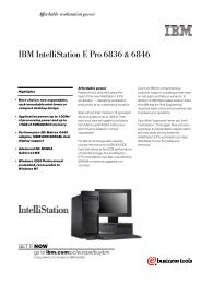
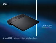
3 Illustrated parts catalogSerial number label locationWhen ordering parts or requesting information, the serial number label, located on the bottom of thecomputer, provides important information that you may need when contacting technical support.(1) Product name (4) <strong>Warranty</strong> period(2) Serial number (5) Model description (select models)(3) Product number22 Chapter 3 Illustrated parts catalog
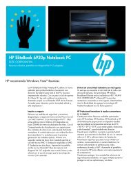
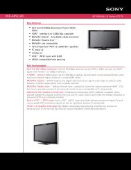
Computer major componentsComputer major components 23
Item Description Spare part number(1) Display assembly (includes 2 WLAN antennas and cables and, on select computer models, 2 WWAN antennasand cables)NOTE:WWAN is available only on select models with 33.8-cm 13.3-in displays.● 33.8-cm (13.3-in) HD (1366x768 resolution) 599553-001● 33.8-cm (13.3-in) HD BrightView 599554-001● 33.8-cm (13.3-in) HD BrightView with webcam 599555-001● 33.8-cm (13.3-in) HD BrightView with webcam and WWAN 599556-001● 33.8-cm (13.3-in) HD with webcam 599557-001● 33.8-cm (13.3-in) HD with webcam and WWAN 599558-001● 33.8-cm (13.3-in) HD (1366x768 resolution) , red 608736-001● 33.8-cm (13.3-in) HD BrightView, red 608737-001● 33.8-cm (13.3-in) HD BrightView with webcam, red 608738-001● 33.8-cm (13.3-in) HD with webcam, red 608739-001● 35.6-cm (14.0-in) HD (1366x768 resolution) 599559-001● 35.6-cm (14.0-in) HD BrightView 599560-001● 35.6-cm (14.0-in) HD BrightView with webcam 599561-001● 35.6-cm (14.0-in) HD with webcam 599562-001● 35.6-cm (14.0-in) HD (1366x768 resolution), red 608740-001● 35.6-cm (14.0-in) HD BrightView, red 608741-001● 35.6-cm (14.0-in) HD BrightView with webcam, red 608742-001● 35.6-cm (14.0-in) HD with webcam, red 608743-001(2) Switch cover● For with 33.8-cm (13.3-in) displays 599567-001● For with 33.8-cm (13.3-in) displays, red 607652-001● For with 35.6-cm (14.0-in) displays 599568-001● For with 35.6-cm (14.0-in) displays, red 607653-001(3) Power connector board (with cable) 599517–001(4) KeyboardIn computer models with 33.8-cm (13.3-in) displays:● For use in Belgium 599572-A41● For use in Brazil 599572-201● For use in Bulgaria 599572-261● For use in Canada (French) 599572-121● For use in Denmark 599572-08124 Chapter 3 Illustrated parts catalog
Item Description Spare part number● For use in Europe 599572-B31● For use in France 599572-051● For use in French Arabic region 599572-DW1● For use in Germany 599572-041● For use in Greece 599572-DJ1● For use in Hungary 599572-211● For use in Iceland 599572-DD1● For use in Israel 599572-BB1● For use in Italy 599572-061● For use in Japan 599572-291● For use in Korea 599572-AD1● For use in Latin America 599572-161● For use in Norway 599572-091● For use in Portugal 599572-131● For use in Russia 599572-251● For use in Saudi Arabia 599572-171● For use in Spain 599572-071● For use in Sweden and Finland 599572-B71● For use in Switzerland 599572-BG1● For use in Taiwan 599572-AB1● For use in Thailand 599572-281● For use in the Adriatic region 599572-BA1● For use in the Czech Republic and Slovakia 599572-A81● For use in the United Kingdom 599572-031● For use in the United States 599572-001● For use in Turkey 599572-141In computer models with 35.6-cm (14.0-in) displays:● For use in Belgium 599573-A41● For use in Brazil 599573-201● For use in Bulgaria 599573-261● For use in Canada (French) 599573-121● For use in Denmark 599573-081● For use in Europe 599573-B31● For use in France 599573-051Computer major components 25
Item Description Spare part number● For use in French Arabic region 599573-DW1● For use in Germany 599573-041● For use in Greece 599573-DJ1● For use in Hungary 599573-211● For use in Iceland 599573-DD1● For use in Israel 599573-BB1● For use in Italy 599573-061● For use in Japan 599573-291● For use in Korea 599573-AD1● For use in Latin America 599573-161● For use in Norway 599573-091● For use in Portugal 599573-131● For use in Russia 599573-251● For use in Saudi Arabia 599573-171● For use in Spain 599573-071● For use in Sweden and Finland 599573-B71● For use in Switzerland 599573-BG1● For use in Taiwan 599573-AB1● For use in Thailand 599573-281● For use in the Adriatic region 599573-BA1● For use in the Czech Republic and Slovakia 599573-A81● For use in the United Kingdom 599573-031● For use in the United States 599573-001● For use in Turkey 599573-141(5) Palm rest (includes TouchPad)● For use with fingerprint reader and 33.8-cm (13.3-in) displays 599549-001● For use with 33.8-cm (13.3-in) displays 599551-001● For use with fingerprint reader and 33.8-cm (13.3-in) displays, red 607648-001● For use with 33.8-cm (13.3-in) displays, red 607650-001● For use with fingerprint reader and 35.6-cm (14.0-in) displays 599550-001● For use with 35.6-cm (14.0-in) displays 599552-001● For use with fingerprint reader and 35.6-cm (14.0-in) displays, red 607649-001● For use with 35.6-cm (14.0-in) displays, red 607651-001(6) Top heat shield/bracket (included with top cover)26 Chapter 3 Illustrated parts catalog
Item Description Spare part number(7) Fan 599544-001(8) Processor heat sinkFor use with discrete graphics subsystems 599653-001For use with Unified Memory Architecture (UMA) graphics subsystems 599546-001(9) Memory module (<strong>PC</strong>3-10600, 1333-MHz, DDR3, shared)2048-MB 598856-0021024-MB 598859-002(10) Bluetooth module cable (included in Cable kit on page 34, part number 599525-001)(11) Bluetooth module (without cable) 537921-001(12) Modem moduleNOTE: The modem module spare part kit does not include a modem module cable. Themodem module cable is included in the Cable kit. See Cable kit on page 34 for moreCable Kit spare part information.High-speed 56K modem for use in all countries and regions except Australia and NewZealand510100-001High-speed 56K modem for use in Australia and New Zealand 510100-011(13) WLAN moduleIntel® Centrino Advanced-N 6200 802.11a/b/g 2x2For use in Andorra, Antigua and Barbuda, Argentina, Aruba, Australia, Austria, Azerbaijan,Bahamas, Bahrain, Barbados, Belgium, Bermuda, Bolivia, Bosnia, Brazil, Brunei, Bulgaria,Canada, the Cayman Islands, Chile, Colombia, Costa Rica, Croatia, Cyprus, the CzechRepublic, Denmark, the Dominican Republic, Ecuador, Egypt, El Salvador, Estonia, Finland,France, French Guiana, Georgia, Germany, Ghana, Greece, Guadeloupe, Guam,Guatemala, Haiti, Herzegovina, Honduras, Hong Kong, Hungary, Iceland, India, Indonesia,Ireland, Israel, Italy, the Ivory Coast, Jamaica, Japan, Jordan, Kenya, Kuwait, Kyrgyzstan,Latvia, Lebanon, Liechtenstein, Lithuania, Luxembourg, Malawi, Malaysia, Malta,Martinique, Mauritius, Mexico, Monaco, Montenegro, Morocco, the Nether Antilles, theNetherlands, New Zealand, Nicaragua, Nigeria, Norway, Oman, Panama, Paraguay, thePeople’s Republic China, Peru, the Philippines, Poland, Portugal, Puerto Rico, Qatar,Romania, San Marino, Saudi Arabia, Senegal, Serbia, Singapore, Slovakia, Slovenia, SouthAfrica, South Korea, Spain, Sweden, Switzerland, Taiwan, Tanzania, Thailand, Trinidad andTobago, Turkey, the United Arab Emirates, the United Kingdom, Uruguay, the U.S. VirginIslands, the United States, Venezuela, and Vietnam572510-001Intel Centrino Wireless-N 1000 802.11b/g/n 1x2Computer major components 27
Item Description Spare part numberFor use in Andorra, Antigua and Barbuda, Argentina, Aruba, Australia, Austria, Azerbaijan,Bahamas, Bahrain, Barbados, Belgium, Bermuda, Bolivia, Bosnia, Brazil, Brunei, Bulgaria,Canada, the Cayman Islands, Chile, Colombia, Costa Rica, Croatia, Cyprus, the CzechRepublic, Denmark, the Dominican Republic, Ecuador, Egypt, El Salvador, Estonia, Finland,France, French Guiana, Georgia, Germany, Ghana, Greece, Guadeloupe, Guam,Guatemala, Haiti, Herzegovina, Honduras, Hong Kong, Hungary, Iceland, India, Indonesia,Ireland, Israel, Italy, the Ivory Coast, Jamaica, Japan, Jordan, Kenya, Kuwait, Kyrgyzstan,Latvia, Lebanon, Liechtenstein, Lithuania, Luxembourg, Malawi, Malaysia, Malta,Martinique, Mauritius, Mexico, Monaco, Montenegro, Morocco, the Nether Antilles, theNetherlands, New Zealand, Nicaragua, Nigeria, Norway, Oman, Panama, Paraguay, thePeople’s Republic China, Peru, the Philippines, Poland, Portugal, Puerto Rico, Qatar,Romania, San Marino, Saudi Arabia, Senegal, Serbia, Singapore, Slovakia, Slovenia, SouthAfrica, South Korea, Spain, Sweden, Switzerland, Taiwan, Tanzania, Thailand, Trinidad andTobago, Turkey, the United Arab Emirates, the United Kingdom, Uruguay, the U.S. VirginIslands, the United States, Venezuela, and Vietnam572520-001Intel Centrino Wireless-N 1000 802.11b/g 1x2 for use in Russia and Ukraine 585984-001Intel WiFi Link 6200 802.11a/g/nFor use in Andorra, Antigua and Barbuda, Argentina, Aruba, Australia, Austria, Azerbaijan,Bahamas, Bahrain, Barbados, Belgium, Bermuda, Bolivia, Bosnia, Brazil, Brunei, Bulgaria,Canada, the Cayman Islands, Chile, Colombia, Costa Rica, Croatia, Cyprus, the CzechRepublic, Denmark, the Dominican Republic, Ecuador, Egypt, El Salvador, Estonia, Finland,France, French Guiana, Georgia, Germany, Ghana, Greece, Guadeloupe, Guam,Guatemala, Haiti, Herzegovina, Honduras, Hong Kong, Hungary, Iceland, India, Indonesia,Ireland, Israel, Italy, the Ivory Coast, Jamaica, Japan, Jordan, Kenya, Kuwait, Kyrgyzstan,Latvia, Lebanon, Liechtenstein, Lithuania, Luxembourg, Malawi, Malaysia, Malta,Martinique, Mauritius, Mexico, Monaco, Montenegro, Morocco, the Nether Antilles, theNetherlands, New Zealand, Nicaragua, Nigeria, Norway, Oman, Panama, Paraguay, thePeople’s Republic China, Peru, the Philippines, Poland, Portugal, Puerto Rico, Qatar,Romania, San Marino, Saudi Arabia, Senegal, Serbia, Singapore, Slovakia, Slovenia, SouthAfrica, South Korea, Spain, Sweden, Switzerland, Taiwan, Tanzania, Thailand, Trinidad andTobago, Turkey, the United Arab Emirates, the United Kingdom, Uruguay, the U.S. VirginIslands, the United States, Venezuela, and Vietnam572509-001Broadcom 4312G 802.11b/g WiFi AdapterFor use in Canada, the Cayman Islands, Guam, Puerto Rico, the United States, and theU.S. Virgin Islands504593-00328 Chapter 3 Illustrated parts catalog
Item Description Spare part numberFor use in Afghanistan, Albania, Algeria, Andorra, Angola, Antigua and Barbuda, Argentina,Armenia, Aruba, Australia, Austria, Azerbaijan, the Bahamas, Bahrain, Bangladesh,Barbados, Belarus, Belgium, Belize, Benin, Bermuda, Bhutan, Bolivia, Bosnia andHerzegovina, Botswana, Brazil, the British Virgin Islands, Brunei, Bulgaria, Burkina Faso,Burundi, Cambodia, Cameroon, Cape Verde, the Central African Republic, Chad, Colombia,Comoros, the Congo, Costa Rica, Croatia, Cyprus, the Czech Republic, Denmark, Djibouti,Dominica, the Dominican Republic, East Timor, Ecuador, Egypt, El Salvador, EquatorialGuinea, Eritrea, Estonia, Ethiopia, Fiji, Finland, France, French Guiana, Gabon, Gambia,Georgia, Germany, Ghana, Gibraltar, Greece, Grenada, Guadeloupe, Guatemala, Guinea,Guinea-Bissau, Guyana, Haiti, Honduras, Hong Kong, Hungary, Iceland, India, Indonesia,Ireland, Israel, Italy, the Ivory Coast, Jamaica, Japan, Jordan, Kazakhstan, Kenya, Kiribati,Kuwait, Kyrgyzstan, Laos, Latvia, Lebanon, Lesotho, Liberia, Liechtenstein, Lithuania,Luxembourg, Macedonia, Madagascar, Malawi, Malaysia, the Maldives, Mali, Malta, theMarshall Islands, Martinique, Mauritania, Mauritius, Mexico, Micronesia, Monaco, Mongolia,Montenegro, Morocco, Mozambique, Namibia, Nauru, Nepal, the Nether Antilles, theNetherlands, New Zealand, Nicaragua, Niger, Nigeria, Norway, Oman, Pakistan, Palau,Panama, Papua New Guinea, Paraguay, the People's Republic of China, Peru, thePhilippines, Poland, Portugal, Qatar, the Republic of Moldova, Romania, Russia, Rwanda,Samoa, San Marino, Sao Tome and Principe, Saudi Arabia, Senegal, Serbia, theSeychelles, Sierra Leone, Singapore, Slovakia, Slovenia, the Solomon Islands, Somalia,South Africa, South Korea, Spain, Sri Lanka, St. Kitts and Nevis, St. Lucia, St. Vincent andthe Grenadines, Suriname, Swaziland, Sweden, Switzerland, Syria, Taiwan, Tajikistan,Tanzania, Thailand, Togo, Tonga, Trinidad and Tobago, Tunisia, Turkey, Turkmenistan,Tuvalu, Uganda, Ukraine, the United Arab Emirates, the United Kingdom, Uruguay,Uzbekistan, Vanuatu, Venezuela, Vietnam, Yemen, Zaire, Zambia, and Zimbabwe504593-004Realtek RTL8191SE 802.11b/g/n 1x1 WiFi Adapter 593533-001(14) WWAN module, Qualcomm EV-DO HSPA 531993-001(15) RTC battery 599516-001(16) Top coverFor use with 33.8-cm (13.3-in) displays 599569-001For use with 35.6-cm (14.0-in) displays 599570-001(17) Processor (includes replacement thermal material)● Intel® Arrandale 520M 2.4-GHz 594187-001● Intel Arrandale 540M 2.53-GHz 594188-001● Intel Arrandale Core 620M 2.26-GHz 587259-001● Intel Arrandale i3-330M 2.13-GHz 597622-001● Intel Arrandale i3-350M 2.26-GHz 597623-001● Intel Arrandale i5-430M 2.26-GHz 597624-001(18) System board (includes replacement thermal material)●For use with Unified Memory Architecture (UMA) graphics subsystem, WWAN module,and 33.8-cm (13.3-in) displays599521-001● For use with UMA graphics subsystem and 33.8-cm (13.3-in) displays 599520-001● For use with discrete graphics subsystem and 33.8-cm (13.3-in) displays 599518-001● For use with UMA graphics subsystem and 35.6-cm (14.0-in) displays 599523-001● For use with discrete graphics subsystem and 35.6-cm (14.0-in) displays 599522-001Computer major components 29
Item Description Spare part number●●For use with UMA graphics subsystem and 35.6-cm (14.0-in) displays in the People'sRepublic of China and RussiaFor use with discrete graphics subsystem and 35.6-cm (14.0-in) displays in thePeople's Republic of China and Russia608267-001608266-001(19) Power cable (included in Cable kit on page 34, part number 599525-001).(20) RJ11 (modem) cable (included in Cable kit on page 34, part number 599525-001)(21) Speakers● For use with 33.8-cm (13.3-in) displays 599566-001● For use with 35.6-cm (14.0-in) displays 605559-001(22) USB connector board and cable 599524-001(23) ExpressCard slot bezel (included in Plastics kit, see Plastics Kit on page 33)(24) Base enclosureFor use in computer models with 33.8-cm (13.3-in) displays 535864-001For use in computer models with 35.6-cm (14.0-in) displays 599515-001(25) Battery9-cell, 93-Wh (2.8Ah) Li-ion 593573-0016-cell, 47-Wh (2.2Ah) Li-ion 593572-001(26) Hard drive (includes hard drive bracket)500-GB, 7200-rpm 599543-001320-GB, 7200-rpm 599542-001250-GB, 7200-rpm 599541-001(27) SIM (provided by your wireless vendor for use with WWAN option)(28) Optical drive (includes bezel)Blu-ray Disc ROM Drive with SuperMulti DVD±R/RW Double-Layer 599538-001DVD±RW SuperMulti Double-Layer Drive with LightScribe 599540-001DVD ROM Drive 599539-00130 Chapter 3 Illustrated parts catalog
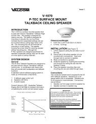
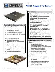
Display assembly componentsItem Description Spare part number(1) Display bezel● For 33.8-cm (13.3-in) displays with webcam 536421-001● For 35.6-cm (14.0-in) displays with webcam 536424-001● For 33.8-cm (13.3-in) displays without webcam 536423-001● For 35.6-cm (14.0-in) displays without webcam 536422-001Display assembly components 31
Item Description Spare part number(2) Webcam module 599571-001(3) Display panel (included with display assembly; see Computer major componentson page 23)(4) Display hinge kit● Display hinge and panel bracket (left and right) for 33.8-cm (13.3-in) displays 599536-001● Display hinge and panel bracket (left and right) for 35.6-cm (14.0-in) displays 599537-001(5) Display cable (includes microphone and, on select models, webcam connector)● Display cable for 33.8-cm (13.3-in) displays with webcam 599534-001● Display cable for 35.6-cm (14.0-in) displays with webcam 605558-001● Display cable for 33.8-cm (13.3-in) displays without webcam 605557-001● Display cable for 35.6-cm (14.0-in) displays without webcam 599535-001(6) WLAN antennas and cables (included with back cover)(7) WWAN antennas and cables (included with back covers used with WWAN option)(8) Display back cover● For 33.8-cm (13.3-in) displays without WWAN 599526-001● For 35.6-cm (14.0-in) displays without WWAN 599527-001● For 33.8-cm (13.3-in) displays with WWAN 599528-001● For 35.6-cm (14.0-in) displays with webcam and without WWAN 605556-001● For 33.8-cm (13.3-in) displays with webcam and without WWAN 607094-001● For 33.8-cm (13.3-in) displays without WWAN, red 607643-001● For 33.8-cm (13.3-in) displays with webcam and without WWAN, red 607644-001● For 33.8-cm (14.0-in) displays without WWAN, red 607645-001● For 35.6-cm (14.0-in) displays with webcam and without WWAN, red 607646-00132 Chapter 3 Illustrated parts catalog
Plastics KitItem Description Spare part numberPlastics Kit: 599563-001(1) ExpressCard slot bezel(2) Optical drive blank (used with no ODD option)RJ11 (modem) connector blank (not illustrated, used with No-Modem option)Plastics Kit 33
Cable kitItem Description Spare part numberCable kit: 599525-001(1) Power cable(2) Bluetooth cable(3) RJ-11 (modem) jack cable34 Chapter 3 Illustrated parts catalog
Mass storage devicesItem Description Spare part number(1) Hard drive (includes bracket)500-GB, 7200-rpm 599543-001320-GB, 7200-rpm 599542-001250-GB, 7200-rpm 599541-001(2) Optical drive (includes bezel)Blu-ray Disc ROM Drive with SuperMulti DVD ±R/RW Double-Layer 599538-001DVD±RW SuperMulti Double-Layer Drive with LightScribe 599540-001DVD-ROM Drive 599539-001Mass storage devices 35
Miscellaneous partsDescriptionSpare part numberAC adapters65-W, 3-pin Smart AC adapter● For use in all countries and regions except India 463958-001● For use in India 577170-00190-W Slimline AC adapter● For use in all countries and regions except India 463955-001● For use in India 535593-001Power cords (AC power, 3-pin, black, 1.83 m)● For use in Argentina 490371-D01● For use in Austria 490371-011● For use in Brazil 490371-202● For use in Denmark 490371-081● For use in Europe 490371-021● For use in India 490371-D61● For use in Israel 490371-BB1● For use in Italy 490371-061● For use in Japan 490371-291● For use in North America 490371-001● For use in the People's Republic of China 490371-AA1● For use in South Africa 490371-AR1● For use in South Korea 490371-AD1● For use in Switzerland 490371-111● For use in Taiwan 490371-AB1● For use in the United Kingdom and Singapore 490371-03136 Chapter 3 Illustrated parts catalog
DescriptionRubber kit (includes display bumpers, display screw covers, base enclosure feet, and displayhinge bumpers)Screw kit, includes:Spare part number599564-001599565-001●●●●●●●●T8 slotted-torx M2.5x6.5T8 slotted-torx M2.5x5.0T8 slotted-torx M2.5x3.0Phillips P1 M2.5x5.0Phillips P1 M2.5x3.0Phillips P1 M2.0x3.0Phillips P0 M2.0x2.5Phillips M3.0x3.5Miscellaneous parts 37
Sequential part number listingSpare partnumberDescription463955-001 90-W Slimline AC adapter for use in all countries and regions except India463958-001 65-W, 3-pin Smart AC adapter for use in all countries and regions except India490371-001 Power cord (AC power, 3-pin, black, 1.83 m), for use in North America490371-011 Power cord (AC power, 3-pin, black, 1.83 m), for use in Austria490371-021 Power cord (AC power, 3-pin, black, 1.83 m), for use in Europe490371-031 Power cord (AC power, 3-pin, black, 1.83 m), for use in the United Kingdom and Singapore490371-061 Power cord (AC power, 3-pin, black, 1.83 m), for use in Italy490371-081 Power cord (AC power, 3-pin, black, 1.83 m), for use in Denmark490371-111 Power cord (AC power, 3-pin, black, 1.83 m), for use in Switzerland490371-202 Power cord (AC power, 3-pin, black, 1.83 m), for use in Brazil490371-291 Power cord (AC power, 3-pin, black, 1.83 m), for use in Japan490371-AA1490371-AB1490371-AD1490371-AR1490371-BB1Power cord (AC power, 3-pin, black, 1.83 m), for use in the People's Republic of ChinaPower cord (AC power, 3-pin, black, 1.83 m), for use in TaiwanPower cord (AC power, 3-pin, black, 1.83 m), for use in South KoreaPower cord (AC power, 3-pin, black, 1.83 m), for use in South AfricaPower cord (AC power, 3-pin, black, 1.83 m), for use in Israel490371-D01 Power cord (AC power, 3-pin, black, 1.83 m), for use in Argentina490371-D61 Power cord (AC power, 3-pin, black, 1.83 m), for use in India483377-001 <strong>HP</strong> Mobile Broadband Module483377-002 <strong>HP</strong> Mobile Broadband Module504593-003 Broadcom 4312G 802.11b/g WiFi Adapter for use in Canada, the Cayman Islands, Guam, Puerto Rico,the United States, and the U.S. Virgin Islands38 Chapter 3 Illustrated parts catalog
Spare partnumberDescription504593-004 Broadcom 4312G 802.11b/g WiFi Adapter for use in Afghanistan, Albania, Algeria, Andorra, Angola,Antigua and Barbuda, Argentina, Armenia, Aruba, Australia, Austria, Azerbaijan, the Bahamas, Bahrain,Bangladesh, Barbados, Belarus, Belgium, Belize, Benin, Bermuda, Bhutan, Bolivia, Bosnia andHerzegovina, Botswana, Brazil, the British Virgin Islands, Brunei, Bulgaria, Burkina Faso, Burundi,Cambodia, Cameroon, Cape Verde, the Central African Republic, Chad, Colombia, Comoros, the Congo,Costa Rica, Croatia, Cyprus, the Czech Republic, Denmark, Djibouti, Dominica, the Dominican Republic,East Timor, Ecuador, Egypt, El Salvador, Equatorial Guinea, Eritrea, Estonia, Ethiopia, Fiji, Finland,France, French Guiana, Gabon, Gambia, Georgia, Germany, Ghana, Gibraltar, Greece, Grenada,Guadeloupe, Guatemala, Guinea, Guinea-Bissau, Guyana, Haiti, Honduras, Hong Kong, Hungary,Iceland, India, Indonesia, Ireland, Israel, Italy, the Ivory Coast, Jamaica, Japan, Jordan, Kazakhstan,Kenya, Kiribati, Kuwait, Kyrgyzstan, Laos, Latvia, Lebanon, Lesotho, Liberia, Liechtenstein, Lithuania,Luxembourg, Macedonia, Madagascar, Malawi, Malaysia, the Maldives, Mali, Malta, the Marshall Islands,Martinique, Mauritania, Mauritius, Mexico, Micronesia, Monaco, Mongolia, Montenegro, Morocco,Mozambique, Namibia, Nauru, Nepal, the Nether Antilles, the Netherlands, New Zealand, Nicaragua,Niger, Nigeria, Norway, Oman, Pakistan, Palau, Panama, Papua New Guinea, Paraguay, the People'sRepublic of China, Peru, the Philippines, Poland, Portugal, Qatar, the Republic of Moldova, Romania,Russia, Rwanda, Samoa, San Marino, Sao Tome and Principe, Saudi Arabia, Senegal, Serbia, theSeychelles, Sierra Leone, Singapore, Slovakia, Slovenia, the Solomon Islands, Somalia, South Africa,South Korea, Spain, Sri Lanka, St. Kitts and Nevis, St. Lucia, St. Vincent and the Grenadines, Suriname,Swaziland, Sweden, Switzerland, Syria, Taiwan, Tajikistan, Tanzania, Thailand, Togo, Tonga, Trinidadand Tobago, Tunisia, Turkey, Turkmenistan, Tuvalu, Uganda, Ukraine, the United Arab Emirates, theUnited Kingdom, Uruguay, Uzbekistan, Vanuatu, Venezuela, Vietnam, Yemen, Zaire, Zambia, andZimbabwe510100-001 High-speed 56K modem for use in all countries and regions except Australia and New Zealand510100-011 High-speed 56K modem for use in Australia and New Zealand531993-001 WWAN module, Qualcomm EV-DO HSPA535593-001 90-W Slimline AC adapter for use in India537921-001 Bluetooth module (without cable)572509-001 Intel WiFi Link 6200 802.11 a/g/n for use in Andorra, Antigua and Barbuda, Argentina, Aruba, Australia,Austria, Azerbaijan, Bahamas, Bahrain, Barbados, Belgium, Bermuda, Bolivia, Bosnia, Brazil, Brunei,Bulgaria, Canada, the Cayman Islands, Chile, Colombia, Costa Rica, Croatia, Cyprus, the CzechRepublic, Denmark, the Dominican Republic, Ecuador, Egypt, El Salvador, Estonia, Finland, France,French Guiana, Georgia, Germany, Ghana, Greece, Guadeloupe, Guam, Guatemala, Haiti, Herzegovina,Honduras, Hong Kong, Hungary, Iceland, India, Indonesia, Ireland, Israel, Italy, the Ivory Coast, Jamaica,Japan, Jordan, Kenya, Kuwait, Kyrgyzstan, Latvia, Lebanon, Liechtenstein, Lithuania, Luxembourg,Malawi, Malaysia, Malta, Martinique, Mauritius, Mexico, Monaco, Montenegro, Morocco, the NetherAntilles, the Netherlands, New Zealand, Nicaragua, Nigeria, Norway, Oman, Panama, Paraguay, thePeople’s Republic China, Peru, the Philippines, Poland, Portugal, Puerto Rico, Qatar, Romania, SanMarino, Saudi Arabia, Senegal, Serbia, Singapore, Slovakia, Slovenia, South Africa, South Korea, Spain,Sweden, Switzerland, Taiwan, Tanzania, Thailand, Trinidad and Tobago, Turkey, the United ArabEmirates, the United Kingdom, Uruguay, the U.S. Virgin Islands, the United States, Venezuela, andVietnam572510-001 Intel Centrino Advanced-N 6200 802.11a/b/g 2x2 for use in Andorra, Antigua and Barbuda, Argentina,Aruba, Australia, Austria, Azerbaijan, Bahamas, Bahrain, Barbados, Belgium, Bermuda, Bolivia, Bosnia,Brazil, Brunei, Bulgaria, Canada, the Cayman Islands, Chile, Colombia, Costa Rica, Croatia, Cyprus, theCzech Republic, Denmark, the Dominican Republic, Ecuador, Egypt, El Salvador, Estonia, Finland,France, French Guiana, Georgia, Germany, Ghana, Greece, Guadeloupe, Guam, Guatemala, Haiti,Herzegovina, Honduras, Hong Kong, Hungary, Iceland, India, Indonesia, Ireland, Israel, Italy, the IvoryCoast, Jamaica, Japan, Jordan, Kenya, Kuwait, Kyrgyzstan, Latvia, Lebanon, Liechtenstein, Lithuania,Luxembourg, Malawi, Malaysia, Malta, Martinique, Mauritius, Mexico, Monaco, Montenegro, Morocco, theNether Antilles, the Netherlands, New Zealand, Nicaragua, Nigeria, Norway, Oman, Panama, Paraguay,the People’s Republic China, Peru, the Philippines, Poland, Portugal, Puerto Rico, Qatar, Romania, SanMarino, Saudi Arabia, Senegal, Serbia, Singapore, Slovakia, Slovenia, South Africa, South Korea, Spain,Sweden, Switzerland, Taiwan, Tanzania, Thailand, Trinidad and Tobago, Turkey, the United ArabEmirates, the United Kingdom, Uruguay, the U.S. Virgin Islands, the United States, Venezuela, andVietnamSequential part number listing 39
Spare partnumberDescription572520-001 Intel Centrino Wireless-N 1000 802.11b/g/n 1x2 for use in Andorra, Antigua and Barbuda, Argentina,Aruba, Australia, Austria, Azerbaijan, Bahamas, Bahrain, Barbados, Belgium, Bermuda, Bolivia, Bosnia,Brazil, Brunei, Bulgaria, Canada, the Cayman Islands, Chile, Colombia, Costa Rica, Croatia, Cyprus, theCzech Republic, Denmark, the Dominican Republic, Ecuador, Egypt, El Salvador, Estonia, Finland,France, French Guiana, Georgia, Germany, Ghana, Greece, Guadeloupe, Guam, Guatemala, Haiti,Herzegovina, Honduras, Hong Kong, Hungary, Iceland, India, Indonesia, Ireland, Israel, Italy, the IvoryCoast, Jamaica, Japan, Jordan, Kenya, Kuwait, Kyrgyzstan, Latvia, Lebanon, Liechtenstein, Lithuania,Luxembourg, Malawi, Malaysia, Malta, Martinique, Mauritius, Mexico, Monaco, Montenegro, Morocco, theNether Antilles, the Netherlands, New Zealand, Nicaragua, Nigeria, Norway, Oman, Panama, Paraguay,the People’s Republic China, Peru, the Philippines, Poland, Portugal, Puerto Rico, Qatar, Romania, SanMarino, Saudi Arabia, Senegal, Serbia, Singapore, Slovakia, Slovenia, South Africa, South Korea, Spain,Sweden, Switzerland, Taiwan, Tanzania, Thailand, Trinidad and Tobago, Turkey, the United ArabEmirates, the United Kingdom, Uruguay, the U.S. Virgin Islands, the United States, Venezuela, andVietnam577170-001 65-W, 3-pin Smart AC adapter for use in India585984-001 Intel Centrino Wireless-N 1000 802.11b/g 1x2 for use in Russia and Ukraine587259-001 Processor, Intel Arrandale Core 620M 2.26-GHz593533-001 Realtek RTL8191SE 802.11b/g/n 1x1 WiFi Adapter593572-001 Battery, 6-cell, 47-Wh (2.2Ah) Li-ion593573-001 Battery, 9-cell, 93-Wh (2.8Ah) Li-ion594187-001 Processor, Intel Arrandale 520M 2.4-GHz594188-001 Processor Intel Arrandale 540M 2.53-GHz597622-001 Processor, Intel Arrandale i3-330M 2.13-GHz597623-001 Processor, Intel Arrandale i3-350M 2.26-GHz597624-001 Processor, Intel Arrandale i5-430M 2.26-GHz598856-002 Memory module (<strong>PC</strong>3-10600 shared), 2048-MB598859-002 Memory module (<strong>PC</strong>3-10600 shared), 1024-MB599514-001 Base enclosure, for use with 33.8-cm (13.3-in) models599515-001 Base enclosure, for use in 35.6-cm (14.0-in) models599516-001 RTC battery599517-001 Power connector board and cable599518-001 System board, for use with 33.8-cm (13.3-in) models and discrete graphics subsystem599520-001 System board, for use with 33.8-cm (13.3-in) models and Unified Memory Architecture (UMA) graphicssubsystem599521-001 System board, for use with 33.8-cm (13.3-in) models and Unified Memory Architecture (UMA) graphicssubsystem and WWAN module599522-001 System board, for use with 35.6-cm (14.0-in) models and discrete graphics subsystem599523-001 System board, for use with 35.6-cm (14.0-in) models and Unified Memory Architecture (UMA) graphicssubsystem599524-001 USB board and cable599525-001 Cable kit40 Chapter 3 Illustrated parts catalog
Spare partnumberDescription599526-001 Display back cover for 33.8-cm (13.3-in) displays without WWAN599527-001 Display back cover for 35.6-cm (14.0-in) displays without WWAN599528-001 Display back cover for 33.8-cm (13.3-in) displays with WWAN599530-001 Display bezel for 33.8-cm (13.3-in) models with webcam599531-001 Display bezel for 35.6-cm (14.0-in) models with webcam599532-001 Display bezel for 33.8-cm (13.3-in) models without webcam599533-001 Display bezel for 35.6-cm (14.0-in) models without webcam599534-001 Display cable for 33.8-cm (13.3-in) displays with webcam599535-001 Display cable for 35.6-cm (14.0-in) displays without webcam599536-001 Display hinge and bracket (left and right) for 33.8-cm (13.3-in) models599537-001 Display hinge and bracket (left and right) for 35.6-cm (14.0-in) models599538-001 Blu-ray Disc ROM Drive with SuperMulti DVD ±R/RW Double-Layer599539-001 DVD ROM Drive599540-001 DVD ±RW SuperMulti Double-Layer Drive with LightScribe599541-001 Hard drive, 250-GB, 7200-rpm599542-001 Hard drive, 320-GB, 7200-rpm599543-001 Hard drive, 500-GB, 7200-rpm599544-001 Fan599549-001 Palm rest with Touchpad and fingerprint reader for use with 33.8-cm (13.3-in) displays599550-001 Palm rest with Touchpad and fingerprint reader for use with 35.6-cm (14.0-in) displays599551-001 Palm rest with Touchpad for use with 33.8-cm (13.3-in) displays, red599552-001 Palm rest with Touchpad for use with 35.6-cm (14.0-in) displays599553-001 Display assembly, 33.8-cm (13.3-in) HD (1366x768 resolution)599554-001 Display assembly, 33.8-cm (13.3-in) HD BrightView599555-001 Display assembly, 33.8-cm (13.3-in) HD BrightView with webcam599556-001 Display assembly, 33.8-cm (13.3-in) HD BrightView with webcam and WWAN599557-001 Display assembly, 33.8-cm (13.3-in) HD with webcam599558-001 Display assembly, 33.8-cm (13.3-in) HD with webcam and WWAN599559-001 Display assembly, 35.6-cm (14.0-in) HD (1366x768 resolution)599560-001 Display assembly, 35.6-cm (14.0-in) HD BrightView599561-001 Display assembly, 35.6-cm (14.0-in) HD BrightView with webcam599562-001 Display assembly, 35.6-cm (14.0-in) HD with webcam599563-001 Plastics kit599564-001 Rubber kitSequential part number listing 41
Spare partnumberDescription599565-001 Screw kit599566-001 Speaker assembly, 33.8-cm (13.3-in)599567-001 Switch cover, 33.8-cm (13.3-in)599568-001 Switch cover, 35.6-cm (14.0-in)599569-001 Top cover, for use with 33.8-cm (13.3-in) models599570-001 Top cover, for use with 35.6-cm (14.0-in) models599571-001 Webcam module599572-001 Keyboard, 33.8-cm (13.3-in), for use in the United States599572-031 Keyboard, 33.8-cm (13.3-in), for use in the United Kingdom599572-041 Keyboard, 33.8-cm (13.3-in), for use in Germany599572-051 Keyboard, 33.8-cm (13.3-in), for use in France599572-061 Keyboard, 33.8-cm (13.3-in), for use in Italy599572-071 Keyboard, 33.8-cm (13.3-in), for use in Spain599572-081 Keyboard, 33.8-cm (13.3-in), for use in Denmark599572-091 Keyboard, 33.8-cm (13.3-in), for use in Norway599572-121 Keyboard, 33.8-cm (13.3-in), for use in Canada (French)599572-131 Keyboard, 33.8-cm (13.3-in), for use in Portugal599572-141 Keyboard, 33.8-cm (13.3-in), for use in Turkey599572-161 Keyboard, 33.8-cm (13.3-in), for use in Latin America599572-171 Keyboard, 33.8-cm (13.3-in), for use in Saudi Arabia599572-201 Keyboard, 33.8-cm (13.3-in), for use in Brazil599572-211 Keyboard, 33.8-cm (13.3-in), for use in Hungary599572-251 Keyboard, 33.8-cm (13.3-in), for use in Russia599572-261 Keyboard, 33.8-cm (13.3-in), for use in Bulgaria599572-281 Keyboard, 33.8-cm (13.3-in), for use in Thailand599572-291 Keyboard, 33.8-cm (13.3-in), for use in Japan599572-A41 Keyboard, 33.8-cm (13.3-in), for use in Belgium599572-A81 Keyboard, 33.8-cm (13.3-in), for use in the Czech Republic and Slovakia599572-AB1599572-AD1Keyboard, 33.8-cm (13.3-in), for use in TaiwanKeyboard, 33.8-cm (13.3-in), for use in South Korea599572-B31 Keyboard, 33.8-cm (13.3-in), for use in Europe599572-B71 Keyboard, 33.8-cm (13.3-in), for use in Sweden and Finland599572-BA1599572-BB1Keyboard, 33.8-cm (13.3-in), for use in the Adriatic regionKeyboard, 33.8-cm (13.3-in), for use in Israel42 Chapter 3 Illustrated parts catalog
Spare partnumber599572-BG1599572-DD1599572-DJ1599572-DW1DescriptionKeyboard, 33.8-cm (13.3-in), for use in SwitzerlandKeyboard, 33.8-cm (13.3-in), for use in IcelandKeyboard, 33.8-cm (13.3-in), for use in GreeceKeyboard, 33.8-cm (13.3-in), for use in French Arabic region599573-001 Keyboard, 35.6-cm (14.0-in), for use in the United States599573-031 Keyboard, 35.6-cm (14.0-in), for use in the United Kingdom599573-041 Keyboard, 35.6-cm (14.0-in), for use in Germany599573-051 Keyboard, 35.6-cm (14.0-in), for use in France599573-061 Keyboard, 35.6-cm (14.0-in), for use in Italy599573-071 Keyboard, 35.6-cm (14.0-in), for use in Spain599573-081 Keyboard, 35.6-cm (14.0-in), for use in Denmark599573-091 Keyboard, 35.6-cm (14.0-in), for use in Norway599573-121 Keyboard, 35.6-cm (14.0-in), for use in Canada (French)599573-131 Keyboard, 35.6-cm (14.0-in), for use in Portugal599573-141 Keyboard, 35.6-cm (14.0-in), for use in Turkey599573-161 Keyboard, 35.6-cm (14.0-in), for use in Latin America599573-171 Keyboard, 35.6-cm (14.0-in), for use in Saudi Arabia599573-201 Keyboard, 35.6-cm (14.0-in), for use in Brazil599573-211 Keyboard, 35.6-cm (14.0-in), for use in Hungary599573-251 Keyboard, 35.6-cm (14.0-in), for use in Russia599573-261 Keyboard, 35.6-cm (14.0-in), for use in Bulgaria599573-281 Keyboard, 35.6-cm (14.0-in), for use in Thailand599573-291 Keyboard, 35.6-cm (14.0-in), for use in Japan599573-A41 Keyboard, 35.6-cm (14.0-in), for use in Belgium599573-A81 Keyboard, 35.6-cm (14.0-in), for use in the Czech Republic and Slovakia599573-AB1599573-AD1Keyboard, 35.6-cm (14.0-in), for use in TaiwanKeyboard, 35.6-cm (14.0-in), for use in Korea599573-B31 Keyboard, 35.6-cm (14.0-in), for use in Europe599573-B71 Keyboard, 35.6-cm (14.0-in), for use in Sweden and Finland599573-BA1599573-BB1599573-BG1599573-DD1599573-DJ1Keyboard, 35.6-cm (14.0-in), for use in the Adriatic regionKeyboard, 35.6-cm (14.0-in), for use in IsraelKeyboard, 35.6-cm (14.0-in), for use in SwitzerlandKeyboard, 35.6-cm (14.0-in), for use in IcelandKeyboard, 35.6-cm (14.0-in), for use in GreeceSequential part number listing 43
Spare partnumber599573-DW1DescriptionKeyboard, 35.6-cm (14.0-in), for use in French Arabic region599653-001 Processor heat sink for use with discrete graphics subsystem599546-001 Processor heat sink for use with Unified Memory Architecture (UMA) graphics subsystem605556-001 Display back cover for 35.6-cm (14.0-in) displays with webcam and without WWAN605557-001 Display cable for 33.8-cm (13.3-in) displays without webcam605558-001 Display cable for 35.6-cm (14.0-in) displays with webcam605559-001 Speaker assembly, 35.6-cm (14.0-in)607094-001 Display back cover for 33.8-cm (13.3-in) displays with webcam and without WWAN607643-001 Display back cover for 33.8-cm (13.3-in) displays without WWAN, red607644-001 Display back cover for 33.8-cm (13.3-in) displays with webcam and without WWAN, red607645-001 Display back cover for 35.6-cm (14.0-in) displays without WWAN, red607646-001 Display back cover for 35.6-cm (14.0-in) displays with webcam and without WWAN, red607648-001 Palm rest with Touchpad and fingerprint reader for use with 33.8-cm (13.3-in) displays, red607649-001 Palm rest with Touchpad and fingerprint reader for use with 35.6-cm (14.0-in) displays, red607650-001 Palm rest with Touchpad for use with 33.8-cm (13.3-in) displays, red607651-001 Palm rest with Touchpad for use with 35.6-cm (14.0-in) displays, red607652-001 Switch cover, 33.8-cm (13.3-in), red607653-001 Switch cover, 35.6-cm (14.0-in), red608266-001 System board, for use with 35.6-cm (14.0-in) models with discrete graphics subsystem in the People'sRepublic of China and Russia608267-001 System board, for use with 35.6-cm (14.0-in) models with Unified Memory Architecture (UMA) graphicssubsystem in the People's Republic of China and Russia608736-001 Display assembly, 33.8-cm (13.3-in) HD (1366x768 resolution) , red608737-001 Display assembly, 33.8-cm (13.3-in) HD BrightView, red608738-001 Display assembly, 33.8-cm (13.3-in) HD BrightView with webcam, red608739-001 Display assembly, 33.8-cm (13.3-in) HD with webcam, red608740-001 Display assembly, 35.6-cm (14.0-in) HD (1366x768 resolution), red608741-001 Display assembly, 35.6-cm (14.0-in) HD BrightView, red608742-001 Display assembly, 35.6-cm (14.0-in) HD BrightView with webcam, red608743-001 Display assembly, 35.6-cm (14.0-in) HD with webcam, red44 Chapter 3 Illustrated parts catalog
4 Removal and replacement proceduresPreliminary replacement requirementsTools requiredYou will need the following tools to complete the removal and replacement procedures:●●●Flat-bladed screwdriverPhillips P0 and P1 screwdriversTorx T8 screwdriverService considerationsPlastic partsThe following sections include some of the considerations that you must keep in mind duringdisassembly and assembly procedures.NOTE: As you remove each subassembly from the computer, place the subassembly (and allaccompanying screws) away from the work area to prevent damage.CAUTION: Using excessive force during disassembly and reassembly can damage plastic parts.Use care when handling the plastic parts. Apply pressure only at the points designated in themaintenance instructions.Preliminary replacement requirements 45
Cables and connectorsDrive handlingCAUTION: When servicing the computer, be sure that cables are placed in their proper locationsduring the reassembly process. Improper cable placement can damage the computer.Cables must be handled with extreme care to avoid damage. Apply only the tension required tounseat or seat the cables during removal and insertion. Handle cables by the connector wheneverpossible. In all cases, avoid bending, twisting, or tearing cables. Be sure that cables are routed insuch a way that they cannot be caught or snagged by parts being removed or replaced. Handle flexcables with extreme care; these cables tear easily.CAUTION: Drives are fragile components that must be handled with care. To prevent damage tothe computer, damage to a drive, or loss of information, observe these precautions:Before removing or inserting a hard drive, shut down the computer. If you are unsure whether thecomputer is off or in Hibernation, turn the computer on, and then shut it down through the operatingsystem.Before handling a drive, be sure that you are discharged of static electricity. While handling a drive,avoid touching the connector.Before removing a diskette drive or optical drive, be sure that a diskette or disc is not in the drive andbe sure that the optical drive tray is closed.Handle drives on surfaces covered with at least one inch of shock-proof foam.Avoid dropping drives from any height onto any surface.After removing a hard drive, an optical drive, or a diskette drive, place it in a static-proof bag.Avoid exposing a hard drive to products that have magnetic fields, such as monitors or speakers.Avoid exposing a drive to temperature extremes or liquids.If a drive must be mailed, place the drive in a bubble pack mailer or other suitable form of protectivepackaging and label the package “FRAGILE.”46 Chapter 4 Removal and replacement procedures
Grounding guidelinesElectrostatic discharge damageElectronic components are sensitive to electrostatic discharge (ESD). Circuitry design and structuredetermine the degree of sensitivity. Networks built into many integrated circuits provide someprotection, but in many cases, ESD contains enough power to alter device parameters or meltsilicon junctions.A discharge of static electricity from a finger or other conductor can destroy static-sensitive devices ormicrocircuitry. Even if the spark is neither felt nor heard, damage may have occurred.An electronic device exposed to ESD may not be affected at all and can work perfectly throughout anormal cycle. Or the device may function normally for a while, then degrade in the internal layers,reducing its life expectancy.CAUTION: To prevent damage to the computer when you are removing or installing internalcomponents, observe these precautions:Keep components in their electrostatic-safe containers until you are ready to install them.Use nonmagnetic tools.Before touching an electronic component, discharge static electricity by using the guidelinesdescribed in this section.Avoid touching pins, leads, and circuitry. Handle electronic components as little as possible.If you remove a component, place it in an electrostatic-safe container.The following table shows how humidity affects the electrostatic voltage levels generated by differentactivities.CAUTION: A product can be degraded by as little as 700 V.Typical electrostatic voltage levelsRelative humidityEvent 10% 40% 55%Walking across carpet 35,000 V 15,000 V 7,500 VWalking across vinyl floor 12,000 V 5,000 V 3,000 VMotions of bench worker 6,000 V 800 V 400 VRemoving DIPS from plastic tube 2,000 V 700 V 400 VRemoving DIPS from vinyl tray 11,500 V 4,000 V 2,000 VRemoving DIPS from Styrofoam 14,500 V 5,000 V 3,500 VRemoving bubble pack from <strong>PC</strong>B 26,500 V 20,000 V 7,000 VPacking <strong>PC</strong>Bs in foam-lined box 21,000 V 11,000 V 5,000 VPreliminary replacement requirements 47
Packaging and transporting guidelinesFollow these grounding guidelines when packaging and transporting equipment:●●●●●●●To avoid hand contact, transport products in static-safe tubes, bags, or boxes.Protect ESD-sensitive parts and assemblies with conductive or approved containers orpackaging.Keep ESD-sensitive parts in their containers until the parts arrive at static-free workstations.Place items on a grounded surface before removing items from their containers.Always be properly grounded when touching a component or assembly.Store reusable ESD-sensitive parts from assemblies in protective packaging or nonconductivefoam.Use transporters and conveyors made of antistatic belts and roller bushings. Be sure thatmechanized equipment used for moving materials is wired to ground and that proper materialsare selected to avoid static charging. When grounding is not possible, use an ionizer to dissipateelectric charges.Workstation guidelinesFollow these grounding workstation guidelines:●●●●●●●●Cover the workstation with approved static-shielding material.Use a wrist strap connected to a properly grounded work surface and use properly groundedtools and equipment.Use conductive field service tools, such as cutters, screwdrivers, and vacuums.When fixtures must directly contact dissipative surfaces, use fixtures made only of static-safematerials.Keep the work area free of nonconductive materials, such as ordinary plastic assembly aids andStyrofoam.Handle ESD-sensitive components, parts, and assemblies by the case or <strong>PC</strong>M laminate. Handlethese items only at static-free workstations.Avoid contact with pins, leads, or circuitry.Turn off power and input signals before inserting or removing connectors or test equipment.48 Chapter 4 Removal and replacement procedures
Equipment guidelinesGrounding equipment must include either a wrist strap or a foot strap at a grounded workstation.●●When seated, wear a wrist strap connected to a grounded system. Wrist straps are flexiblestraps with a minimum of one megohm ±10% resistance in the ground cords. To provide properground, wear a strap snugly against the skin at all times. On grounded mats with banana-plugconnectors, use alligator clips to connect a wrist strap.When standing, use foot straps and a grounded floor mat. Foot straps (heel, toe, or boot straps)can be used at standing workstations and are compatible with most types of shoes or boots. Onconductive floors or dissipative floor mats, use foot straps on both feet with a minimum of onemegohm resistance between the operator and ground. To be effective, the conductive stripsmust be worn in contact with the skin.The following grounding equipment is recommended to prevent electrostatic damage:●●●●●●●●●●●●Antistatic tapeAntistatic smocks, aprons, and sleeve protectorsConductive bins and other assembly or soldering aidsNonconductive foamConductive tabletop workstations with ground cords of one megohm resistanceStatic-dissipative tables or floor mats with hard ties to the groundField service kitsStatic awareness labelsMaterial-handling packagesNonconductive plastic bags, tubes, or boxesMetal tote boxesElectrostatic voltage levels and protective materialsThe following table lists the shielding protection provided by antistatic bags and floor mats.Material Use Voltage protection levelAntistatic plastic Bags 1,500 VCarbon-loaded plastic Floor mats 7,500 VMetallized laminate Floor mats 5,000 VPreliminary replacement requirements 49
Component replacement proceduresThis section provides removal and replacement procedures.There are as many as 83 screws, in 8 different sizes, that must be removed, replaced, or loosenedwhen servicing the computer. Make special note of each screw size and location during removal andreplacement.Serial number labelThe serial number label, located on the bottom of the computer, provides important information thatyou may need when contacting technical support.NOTE:Serial number label color varies on select models.(1) Product name (4) <strong>Warranty</strong> period(2) Serial number (5) Model description (select models)(3) Product numberComputer feetThe computer feet are adhesive-backed rubber pads. The feet are included in the rubber kit, sparepart number 535793-001. There are 4 rubber feet that attach to the base enclosure in the locationsillustrated below.50 Chapter 4 Removal and replacement procedures
BatteryDescriptionSpare part numberBattery9-cell, 93-Wh (2.8Ah) Li-ion 593573-0016-cell, 47-Wh (2.2Ah) Li-ion 593572-001Before disassembling the computer, follow these steps:1. Shut down the computer. If you are unsure whether the computer is off or in Hibernation, turnthe computer on, and then shut it down through the operating system.2. Disconnect all external devices connected to the computer.3. Disconnect the power from the computer by first unplugging the power cord from the AC outletand then unplugging the AC adapter from the computer.Remove the battery:1. Turn the computer upside-down on a flat surface with the battery bay toward you.2. Slide the battery release latches (1) to release the battery.3. Remove the battery (2) from the computer.Install the battery by inserting it into the battery bay until you hear a click.Component replacement procedures 51
SIMNOTE:This section applies only to select models with WWAN capability.NOTE: If there is a SIM inserted in the SIM slot, it must be removed before disassembling thecomputer. Be sure that the SIM is reinserted in the SIM slot after reassembling the computer.Before removing the SIM, follow these steps:1. Shut down the computer. If you are unsure whether the computer is off or in Hibernation, turnthe computer on, and then shut it down through the operating system.2. Disconnect all external devices connected to the computer.3. Disconnect the power from the computer by first unplugging the power cord from the AC outlet,and then unplugging the AC adapter from the computer.4. Remove the battery (see Battery on page 51).Remove the SIM:1. Push on the SIM (1) to release it from the SIM slot.2. Remove the SIM (2) from the computer.Install the SIM by inserting it into the SIM slot and pushing until you hear a click.CAUTION: If a SIM is inserted backwards or upside down, the battery may not snap into placeproperly and could damage the SIM and the SIM connector.To prevent damage to the connectors, use minimal force when inserting a SIM.52 Chapter 4 Removal and replacement procedures
Switch coverDescriptionSpare part numberSwitch cover● For with 33.8-cm (13.3-in) displays 599567-001● For with 33.8-cm (13.3-in) displays, red 607652-001● For with 35.6-cm (14.0-in) displays 599568-001● For with 35.6-cm (14.0-in) displays, red 607653-001Before removing the switch cover, follow these steps:1. Shut down the computer. If you are unsure whether the computer is off or in Hibernation, turnthe computer on, and then shut it down through the operating system.2. Disconnect all external devices connected to the computer.3. Disconnect the power from the computer by first unplugging the power cord from the AC outletand then unplugging the AC adapter from the computer.4. Remove the battery (see Battery on page 51).Remove the switch cover:1. Position the computer upside down with the rear toward you.2. Remove the four PM2.5×3.0 screws in the battery bay.3. Open the computer as far as possible.Component replacement procedures 53
4. Slide the switch cover back (1), and then remove it from the computer (2).Reverse this procedure to install the switch cover and keyboard.54 Chapter 4 Removal and replacement procedures
KeyboardDescriptionSpare part numberKeyboardFor computer models with 33.8-cm (13.3-in) displaysFor computer models with 35.6-cm (14.0-in) displays:599572-xxx599573-xxxNOTE: For a detailed list of keyboards see the parts list in Computer major components on page 23Before removing the keyboard, follow these steps:1. Shut down the computer. If you are unsure whether the computer is off or in Hibernation, turnthe computer on, and then shut it down through the operating system.2. Disconnect all external devices connected to the computer.3. Disconnect the power from the computer by first unplugging the power cord from the AC outletand then unplugging the AC adapter from the computer.4. Remove the battery (see Battery on page 51).5. Remove the switch cover (see Switch cover on page 53).Remove the keyboard:1. Remove the three Phillips PM2.5×3.0 screws that secure the keyboard to the computer.NOTE: On computer models with 35.6-cm (14.0-in) displays, remove four screws that securethe keyboard to the computer.Component replacement procedures 55
2. Slide the keyboard back toward the display (1), and then rotate it right (2) until it rests upsidedown on the right side of the computer.3. Release the zero insertion force (ZIF) connector (1) to which the keyboard cable is attached, anddisconnect the keyboard cable (2) from the system board.4. Remove the keyboard (3).56 Chapter 4 Removal and replacement procedures
Memory moduleDescriptionSpare part numberMemory module (<strong>PC</strong>3-10600, 1333-MHz, DDR3, shared)2048-MB 598856-0021024-MB 598859-002Before removing the memory module, follow these steps:1. Shut down the computer. If you are unsure whether the computer is off or in Hibernation, turnthe computer on, and then shut it down through the operating system.2. Disconnect all external devices connected to the computer.3. Disconnect the power from the computer by first unplugging the power cord from the AC outletand then unplugging the AC adapter from the computer.4. Remove the battery (see Battery on page 51).5. Remove the switch cover (see Switch cover on page 53).6. Remove the keyboard (see Keyboard on page 55).NOTE: You can release the keyboard without removing the keyboard cable from the systemboard, and then rotate it right until it rests upside down on the right side of the computer toremove the memory modules.Remove the memory module:1. Position the computer right-side up with the front toward you.2. Spread the retaining tabs (1) on each side of the memory module slot to release the memorymodule. (The edge of the module opposite the slot rises away from the computer.)Component replacement procedures 57
3. Remove the memory module (2) by pulling the module away from the slot at an angle.NOTE: Memory modules are designed with a notch (3) to prevent incorrect insertion into thememory module slot.Reverse this procedure to install a memory module.58 Chapter 4 Removal and replacement procedures
Optical driveNOTE:All optical drive spare part kits include an optical drive bezel.DescriptionSpare part numberBlu-ray ROM with LightScribe DVD±R/RW SuperMulti DL Drive 599538-001DVD ±RW SuperMulti Double-Layer Drive with LightScribe 599540-001DVD ROM Drive 599539-001Before removing the optical drive, follow these steps:1. Shut down the computer. If you are unsure whether the computer is off or in Hibernation, turnthe computer on, and then shut it down through the operating system.2. Disconnect all external devices connected to the computer.3. Disconnect the power from the computer by first unplugging the power cord from the AC outletand then unplugging the AC adapter from the computer.4. Remove the battery (see Battery on page 51).5. Remove the switch cover (see Switch cover on page 53).6. Remove the keyboard (see Keyboard on page 55)NOTE: You can release the keyboard without removing the keyboard cable from the systemboard, and then rotate it left until it rests upside down on the left side of the computer to removethe optical drive .Remove the optical drive:1. Position the computer with the right side toward you.2. Remove the Phillips PM2.5×5.0 screw (1) that secures the optical drive to the computer.3. Insert a flat-bladed screwdriver or similar tool into the access point on the top cover to the opticaldrive bracket (2) and press the to the right to release the optical drive from the computer.Component replacement procedures 59
4. Remove the optical drive (3) from the computer.5. If it is necessary to replace the optical drive bracket, position the optical drive with the reartoward you.6. Remove the two Phillips PM2.0×3.0 screws (1) that secure the optical drive bracket to the opticaldrive.7. Remove the optical drive bracket (2).Reverse this procedure to reassemble and install an optical drive.60 Chapter 4 Removal and replacement procedures
Power connector boardDescriptionSpare part numberPower connector board with cable 599517–001Before removing the power connector board, follow these steps:1. Shut down the computer. If you are unsure whether the computer is off or in Hibernation, turnthe computer on, and then shut it down through the operating system.2. Disconnect all external devices connected to the computer.3. Disconnect the power from the computer by first unplugging the power cord from the AC outletand then unplugging the AC adapter from the computer.4. Remove the battery (see Battery on page 51).5. Switch cover (see Switch cover on page 53)Remove the power connector board:1. Release the ZIF connector that connects the power connector board cable to the system board(1), and then disconnect the power connector board cable (2).2. Gently pull the power connector board away from the double-sided tape that secures the boardto the base enclosure.3. Remove the power connector board (3).Reverse this procedure to install the power connector board.Component replacement procedures 61
SpeakersDescriptionSpare part numberSpeakers for use in computer models with 33.8-cm (13.3-in) displays 599566-001Speakers for use in computer models with 35.6-cm (14.0-in) displays 605559-001Before removing the speakers, follow these steps:1. Shut down the computer. If you are unsure whether the computer is off or in Hibernation, turnthe computer on, and then shut it down through the operating system.2. Disconnect all external devices connected to the computer.3. Disconnect the power from the computer by first unplugging the power cord from the AC outletand then unplugging the AC adapter from the computer.4. Remove the battery (see Battery on page 51).5. Remove the switch cover and keyboard (see Switch cover on page 53).Remove the speakers:1. Position the computer right-side up with the front toward you.2. Disconnect the speaker cable (1) from the system board.NOTE:The two speakers are connected with a single cable.3. Remove the two Phillips PM2.5×3.0 screws (2) that secure the speakers to the base enclosure.62 Chapter 4 Removal and replacement procedures
4. Remove the speaker cable from the clips and routing channel, and then remove the speakersfrom the computer (3).Reverse this procedure to install the speakers.Component replacement procedures 63
WWAN moduleNOTE: Only select models with include a WWAN module (see Product description on page 1).DescriptionSpare part numberQualcomm EV-DO HSPA 531993-001CAUTION: To prevent an unresponsive system, replace the wireless module only with a wirelessmodule authorized for use in the computer by the governmental agency that regulates wirelessdevices in your country or region. If you replace the module and then receive a warning message,remove the module to restore computer functionality, and then contact technical support through Helpand Support.Before removing the WWAN module, follow these steps:1. Shut down the computer. If you are unsure whether the computer is off or in Hibernation, turnthe computer on, and then shut it down through the operating system.2. Disconnect all external devices connected to the computer.3. Disconnect the power from the computer by first unplugging the power cord from the AC outletand then unplugging the AC adapter from the computer.4. Remove the battery (see Battery on page 51).5. Remove the switch cover (see Switch cover on page 53)6. Remove the keyboard (see Keyboard on page 55)Remove the WWAN module:1. Position the computer right-side up with the front toward you.2. Disconnect the WWAN antenna cables (1) from the terminals on the WWAN module.NOTE: The red WWAN antenna cable is connected to the WLAN module “Main” terminal. Theblue WWAN antenna cable is connected to the WWAN module “Aux” terminal.3. Remove the two Phillips PM2.5×3.0 screws (2) that secure the WWAN module to the computer.(The module tilts up.)64 Chapter 4 Removal and replacement procedures
4. Remove the WWAN module (3) by pulling the module away from the slot at an angle.NOTE:WWAN modules are designed with a notch (4) to prevent incorrect insertion.Reverse this procedure to install the WWAN module.Component replacement procedures 65
Palm restDescriptionSpare part numberPalm rest (includes TouchPad)● For use with fingerprint reader and 33.8-cm (13.3-in) displays 599549-001● For use with 33.8-cm (13.3-in) displays 599551-001● For use with fingerprint reader and 33.8-cm (13.3-in) displays, red 607648-001● For use with 33.8-cm (13.3-in) displays, red 607650-001● For use with fingerprint reader and 35.6-cm (14.0-in) displays 599550-001● For use with 35.6-cm (14.0-in) displays 599552-001● For use with fingerprint reader and 35.6-cm (14.0-in) displays, red 607649-001● For use with 35.6-cm (14.0-in) displays, red 607651-001Before removing the palm rest, follow these steps:1. Shut down the computer. If you are unsure whether the computer is off or in Hibernation, turnthe computer on, and then shut it down through the operating system.2. Disconnect all external devices connected to the computer.3. Disconnect the power from the computer by first unplugging the power cord from the AC outletand then unplugging the AC adapter from the computer.4. Remove the battery (see Battery on page 51).5. Remove the switch cover (see Switch cover on page 53)6. Remove the keyboard (see Keyboard on page 55)Remove the palm rest:1. Position the computer right-side up with the front toward you.2. Remove the three Phillips PM2.5×3.0 broadhead screws (1) that secure the palm rest to thecomputer.66 Chapter 4 Removal and replacement procedures
3. Slide the palm rest to the right (2), and then turn it over from the front edge (3) until it restsupside down on the top cover.4. Release the fingerprint reader connector (1), and then remove the fingerprint reader cable (2)from the system board.5. Release the TouchPad cable connector (3), and then remove the TouchPad cable (4) from thesystem board.6. Remove the palm rest (5).Reverse this procedure to install the palm rest.Component replacement procedures 67
Hard driveNOTE:The hard drive spare part kit includes a hard drive bracket.DescriptionSpare part number500-GB, 7200-rpm hard drive 599543-001320-GB, 7200-rpm hard drive 599542-001250-GB, 7200-rpm hard drive 599541-001Before removing the hard drive, follow these steps:1. Shut down the computer. If you are unsure whether the computer is off or in Hibernation, turnthe computer on, and then shut it down through the operating system.2. Disconnect all external devices connected to the computer.3. Disconnect the power from the computer by first unplugging the power cord from the AC outletand then unplugging the AC adapter from the computer.4. Remove the battery (see Battery on page 51).5. Remove the following components:a. Switch cover (see Switch cover on page 53)b. Keyboard (see Keyboard on page 55)c. Palm rest (see Palm rest on page 66)Remove the hard drive:1. Position the computer right-side up with the front toward you.2. Remove the two Phillips PM2.0×3.0 screws (1) and loosen the Phillips PM2.5×10.0 captivescrew (2) that secures the hard drive to the computer.3. Grasp the Mylar tab on the hard drive and slide the hard drive (3) to the left to disconnect it fromthe system board.68 Chapter 4 Removal and replacement procedures
4. Remove the hard drive (4) from the hard drive bay.5. If it is necessary to replace the hard drive bracket, remove the two Phillips PM3.0×3.0 hard drivebracket screws (1) from each side of the hard drive.6. Lift the bracket (2) straight up to remove it from the hard drive.Reverse this procedure to reassemble and install the hard drive.Component replacement procedures 69
RTC batteryDescriptionSpare part numberRTC battery 599516-001Before removing the RTC battery, follow these steps:1. Shut down the computer. If you are unsure whether the computer is off or in Hibernation, turnthe computer on, and then shut it down through the operating system.2. Disconnect all external devices connected to the computer.3. Disconnect power from the computer by first unplugging the power cord from the AC outlet andthen unplugging the AC adapter from the computer.4. Remove the following components:a. Battery (see Battery on page 51)b. Switch cover (see Switch cover on page 53)c. Keyboard (see Keyboard on page 55)d. Palm rest (see Palm rest on page 66)Remove the RTC battery:1. Disconnect the RTC battery connector from the system board (1).2. Remove the RTC battery from the system board (2).Reverse this procedure to install the RTC battery.70 Chapter 4 Removal and replacement procedures
WLAN moduleDescriptionSpare part numberIntel® Centrino Advanced-N 6200 802.11a/b/g 2x2For use in Andorra, Antigua and Barbuda, Argentina, Aruba, Australia, Austria, Azerbaijan,Bahamas, Bahrain, Barbados, Belgium, Bermuda, Bolivia, Bosnia, Brazil, Brunei, Bulgaria,Canada, the Cayman Islands, Chile, Colombia, Costa Rica, Croatia, Cyprus, the Czech Republic,Denmark, the Dominican Republic, Ecuador, Egypt, El Salvador, Estonia, Finland, France, FrenchGuiana, Georgia, Germany, Ghana, Greece, Guadeloupe, Guam, Guatemala, Haiti, Herzegovina,Honduras, Hong Kong, Hungary, Iceland, India, Indonesia, Ireland, Israel, Italy, the Ivory Coast,Jamaica, Japan, Jordan, Kenya, Kuwait, Kyrgyzstan, Latvia, Lebanon, Liechtenstein, Lithuania,Luxembourg, Malawi, Malaysia, Malta, Martinique, Mauritius, Mexico, Monaco, Montenegro,Morocco, the Nether Antilles, the Netherlands, New Zealand, Nicaragua, Nigeria, Norway, Oman,Panama, Paraguay, the People’s Republic China, Peru, the Philippines, Poland, Portugal, PuertoRico, Qatar, Romania, San Marino, Saudi Arabia, Senegal, Serbia, Singapore, Slovakia, Slovenia,South Africa, South Korea, Spain, Sweden, Switzerland, Taiwan, Tanzania, Thailand, Trinidadand Tobago, Turkey, the United Arab Emirates, the United Kingdom, Uruguay, the U.S. VirginIslands, the United States, Venezuela, and Vietnam572510-001Intel Centrino Wireless-N 1000 802.11b/g/n 1x2For use in Andorra, Antigua and Barbuda, Argentina, Aruba, Australia, Austria, Azerbaijan,Bahamas, Bahrain, Barbados, Belgium, Bermuda, Bolivia, Bosnia, Brazil, Brunei, Bulgaria,Canada, the Cayman Islands, Chile, Colombia, Costa Rica, Croatia, Cyprus, the Czech Republic,Denmark, the Dominican Republic, Ecuador, Egypt, El Salvador, Estonia, Finland, France, FrenchGuiana, Georgia, Germany, Ghana, Greece, Guadeloupe, Guam, Guatemala, Haiti, Herzegovina,Honduras, Hong Kong, Hungary, Iceland, India, Indonesia, Ireland, Israel, Italy, the Ivory Coast,Jamaica, Japan, Jordan, Kenya, Kuwait, Kyrgyzstan, Latvia, Lebanon, Liechtenstein, Lithuania,Luxembourg, Malawi, Malaysia, Malta, Martinique, Mauritius, Mexico, Monaco, Montenegro,Morocco, the Nether Antilles, the Netherlands, New Zealand, Nicaragua, Nigeria, Norway, Oman,Panama, Paraguay, the People’s Republic China, Peru, the Philippines, Poland, Portugal, PuertoRico, Qatar, Romania, San Marino, Saudi Arabia, Senegal, Serbia, Singapore, Slovakia, Slovenia,South Africa, South Korea, Spain, Sweden, Switzerland, Taiwan, Tanzania, Thailand, Trinidadand Tobago, Turkey, the United Arab Emirates, the United Kingdom, Uruguay, the U.S. VirginIslands, the United States, Venezuela, and Vietnam572520-001Intel Centrino Wireless-N 1000 802.11b/g 1x2 for use in Russia and Ukraine 585984-001Intel WiFi Link 6200 802.11a/g/nFor use in Andorra, Antigua and Barbuda, Argentina, Aruba, Australia, Austria, Azerbaijan,Bahamas, Bahrain, Barbados, Belgium, Bermuda, Bolivia, Bosnia, Brazil, Brunei, Bulgaria,Canada, the Cayman Islands, Chile, Colombia, Costa Rica, Croatia, Cyprus, the Czech Republic,Denmark, the Dominican Republic, Ecuador, Egypt, El Salvador, Estonia, Finland, France, FrenchGuiana, Georgia, Germany, Ghana, Greece, Guadeloupe, Guam, Guatemala, Haiti, Herzegovina,Honduras, Hong Kong, Hungary, Iceland, India, Indonesia, Ireland, Israel, Italy, the Ivory Coast,Jamaica, Japan, Jordan, Kenya, Kuwait, Kyrgyzstan, Latvia, Lebanon, Liechtenstein, Lithuania,Luxembourg, Malawi, Malaysia, Malta, Martinique, Mauritius, Mexico, Monaco, Montenegro,Morocco, the Nether Antilles, the Netherlands, New Zealand, Nicaragua, Nigeria, Norway, Oman,Panama, Paraguay, the People’s Republic China, Peru, the Philippines, Poland, Portugal, PuertoRico, Qatar, Romania, San Marino, Saudi Arabia, Senegal, Serbia, Singapore, Slovakia, Slovenia,South Africa, South Korea, Spain, Sweden, Switzerland, Taiwan, Tanzania, Thailand, Trinidadand Tobago, Turkey, the United Arab Emirates, the United Kingdom, Uruguay, the U.S. VirginIslands, the United States, Venezuela, and Vietnam572509-001Broadcom 4312G 802.11b/g WiFi AdapterFor use in Canada, the Cayman Islands, Guam, Puerto Rico, the United States, and the U.S.Virgin Islands504593-003Component replacement procedures 71
DescriptionFor use in Afghanistan, Albania, Algeria, Andorra, Angola, Antigua and Barbuda, Argentina,Armenia, Aruba, Australia, Austria, Azerbaijan, the Bahamas, Bahrain, Bangladesh, Barbados,Belarus, Belgium, Belize, Benin, Bermuda, Bhutan, Bolivia, Bosnia and Herzegovina, Botswana,Brazil, the British Virgin Islands, Brunei, Bulgaria, Burkina Faso, Burundi, Cambodia, Cameroon,Cape Verde, the Central African Republic, Chad, Colombia, Comoros, the Congo, Costa Rica,Croatia, Cyprus, the Czech Republic, Denmark, Djibouti, Dominica, the Dominican Republic, EastTimor, Ecuador, Egypt, El Salvador, Equatorial Guinea, Eritrea, Estonia, Ethiopia, Fiji, Finland,France, French Guiana, Gabon, Gambia, Georgia, Germany, Ghana, Gibraltar, Greece, Grenada,Guadeloupe, Guatemala, Guinea, Guinea-Bissau, Guyana, Haiti, Honduras, Hong Kong,Hungary, Iceland, India, Indonesia, Ireland, Israel, Italy, the Ivory Coast, Jamaica, Japan, Jordan,Kazakhstan, Kenya, Kiribati, Kuwait, Kyrgyzstan, Laos, Latvia, Lebanon, Lesotho, Liberia,Liechtenstein, Lithuania, Luxembourg, Macedonia, Madagascar, Malawi, Malaysia, the Maldives,Mali, Malta, the Marshall Islands, Martinique, Mauritania, Mauritius, Mexico, Micronesia, Monaco,Mongolia, Montenegro, Morocco, Mozambique, Namibia, Nauru, Nepal, the Nether Antilles, theNetherlands, New Zealand, Nicaragua, Niger, Nigeria, Norway, Oman, Pakistan, Palau, Panama,Papua New Guinea, Paraguay, the People's Republic of China, Peru, the Philippines, Poland,Portugal, Qatar, the Republic of Moldova, Romania, Russia, Rwanda, Samoa, San Marino, SaoTome and Principe, Saudi Arabia, Senegal, Serbia, the Seychelles, Sierra Leone, Singapore,Slovakia, Slovenia, the Solomon Islands, Somalia, South Africa, South Korea, Spain, Sri Lanka,St. Kitts and Nevis, St. Lucia, St. Vincent and the Grenadines, Suriname, Swaziland, Sweden,Switzerland, Syria, Taiwan, Tajikistan, Tanzania, Thailand, Togo, Tonga, Trinidad and Tobago,Tunisia, Turkey, Turkmenistan, Tuvalu, Uganda, Ukraine, the United Arab Emirates, the UnitedKingdom, Uruguay, Uzbekistan, Vanuatu, Venezuela, Vietnam, Yemen, Zaire, Zambia, andZimbabweSpare part number504593-004Realtek RTL8191SE 802.11b/g/n 1x1 WiFi Adapter 593533-001CAUTION: To prevent an unresponsive system, replace the wireless module only with a wirelessmodule authorized for use in the computer by the governmental agency that regulates wirelessdevices in your country or region. If you replace the module and then receive a warning message,remove the module to restore computer functionality, and then contact technical support through Helpand Support.Before removing the WLAN module, follow these steps:1. Shut down the computer. If you are unsure whether the computer is off or in Hibernation, turnthe computer on, and then shut it down through the operating system.2. Disconnect all external devices connected to the computer.3. Disconnect the power from the computer by first unplugging the power cord from the AC outletand then unplugging the AC adapter from the computer.4. Remove the battery (see Battery on page 51).5. Remove the following components:a. Switch cover (see Switch cover on page 53)b. Keyboard (see Keyboard on page 55)c. Palm rest (see Palm rest on page 66)72 Chapter 4 Removal and replacement procedures
Remove the WLAN module:1. Position the computer right-side up with the front toward you.2. Disconnect the WLAN antenna cables (1) from the terminals on the WLAN module.NOTE: The black WLAN antenna cable is connected to the WLAN module “Main” terminal.The white WLAN antenna cable is connected to the WLAN module “Aux” terminal.3. Remove the two Phillips PM2.5×3.0 screws (2) that secure the WLAN module to the computer.(The edge of the module opposite the slot rises away from the computer.)4. Remove the WLAN module (3) by pulling the module away from the slot at an angle.NOTE:WLAN modules are designed with a notch (4) to prevent incorrect insertion.Reverse this procedure to install the WLAN module.Component replacement procedures 73
Bluetooth moduleDescriptionBluetooth module (Bluetooth module cable included in the Cable kit, part number 599525-001,see Cable kit on page 34)Spare part number537921-001Before removing the Bluetooth module, follow these steps:1. Shut down the computer. If you are unsure whether the computer is off or in Hibernation, turnthe computer on, and then shut it down through the operating system.2. Disconnect all external devices connected to the computer.3. Disconnect the power from the computer by first unplugging the power cord from the AC outletand then unplugging the AC adapter from the computer.4. Remove the battery (see Battery on page 51).5. Remove the following components:a. Switch cover (see Switch cover on page 53)b. Keyboard (see Keyboard on page 55)c. Palm rest (see Palm rest on page 66)Remove the Bluetooth module:1. Position the computer right-side up with the front toward you.2. Remove the Bluetooth module from the base enclosure (1).3. Disconnect the Bluetooth module cable (2), and then remove the Bluetooth module.74 Chapter 4 Removal and replacement procedures
4. Remove the Bluetooth module cable (3) from the system board.Reverse this procedure to install the Bluetooth module.Component replacement procedures 75
Heat sink and fanNOTE:The heat sink spare part kit includes replacement thermal material.DescriptionSpare part numberFan 599544-001Processor heat sinkFor use with discrete graphics subsystems 599653-001For use with Unified Memory Architecture (UMA) graphics subsystems 599546-001Before removing the heat sink, follow these steps:1. Shut down the computer. If you are unsure whether the computer is off or in Hibernation, turnthe computer on, and then shut it down through the operating system.2. Disconnect all external devices connected to the computer.3. Disconnect the power from the computer by first unplugging the power cord from the AC outletand then unplugging the AC adapter from the computer.4. Remove the battery (see Battery on page 51).5. Remove the following components:a. Switch cover (see Switch cover on page 53)b. Keyboard (see Keyboard on page 55)c. Palm rest (see Palm rest on page 66)Remove the heat sink:1. Position the computer right-side up with the front toward you.2. Remove the six Phillips PM2.5×3.0 screws (1) that secure the heat shield to the top cover.3. Remove the Phillips PM2.5×5.0 screw (2) that secures the heat shield to the top cover.76 Chapter 4 Removal and replacement procedures
4. Lift the right edge of the heat shield to disengage the tabs on the left side of the heat shield fromthe top cover, and then remove the heat shield (3).5. Disconnect the fan cable from the system board (1).6. Loosen the 2.0×5.0 captive screw from the system board, and then remove the fan (3).Component replacement procedures 77
7. Following the sequence stamped into the heat sink, loosen the four PM2.5×10.0 captive screws(1) that secure the heat sink to the processor.NOTE: Loosen the two additional screws that secure the heat sink to the graphics devices onmodels with discrete graphics subsystem memory.8. Lift the heat sink off the processor (2), and then lift the heat sink up and to the right to removethe heat sink from the base enclosure (3).NOTE: The thermal material must be thoroughly cleaned from the surfaces heat sink for thediscrete system board (1), (2), and (3), and the system board (4), (5), and (6) each time the heat sinkis removed. Replacement thermal material is included with all heat sink, system board, and processorspare part kits.78 Chapter 4 Removal and replacement procedures
NOTE: The thermal material must be thoroughly cleaned from the surfaces of heat sink for the UMAsystem board (1), (2), and (3) and the system board components (3), (4) and (5) each time the heatsink is removed. Replacement thermal material is included with all heat sink, system board, andprocessor spare part kits.Reverse this procedure to install the heat sink and fan.Component replacement procedures 79
ProcessorNOTE:The processor spare part kit includes replacement thermal material.DescriptionSpare part numberProcessor (includes replacement thermal material) (not illustrated)● Intel Arrandale 520M 2.4-GHz 594187-001● Intel Arrandale 540M 2.53-GHz 594188-001● Intel Arrandale Core 620M 2.26-GHz 587259-001● Intel Arrandale i3-330M 2.13-GHz 597622-001● Intel Arrandale i3-350M 2.26-GHz 597623-001● Intel Arrandale i5-430M 2.26-GHz 597624-001Before removing the processor, follow these steps:1. Shut down the computer. If you are unsure whether the computer is off or in Hibernation, turnthe computer on, and then shut it down through the operating system.2. Disconnect all external devices connected to the computer.3. Disconnect the power from the computer by first unplugging the power cord from the AC outletand then unplugging the AC adapter from the computer.4. Remove the battery (see Battery on page 51).5. Remove the following components:a. Switch cover (see Switch cover on page 53)b. Keyboard (see Keyboard on page 55)c. Optical drive (see Optical drive on page 59)d. Speakers (see Speakers on page 62)e. Palm rest (see Palm rest on page 66)f. Top cover (see Top cover on page 91)Remove the processor:1. Position the computer right-side up with the front toward you.2. Use a flat-bladed screwdriver to turn the processor locking screw (1) one-half turncounterclockwise until you hear a click.80 Chapter 4 Removal and replacement procedures
3. Lift the processor (2) straight up and remove it.NOTE: When you install the processor, the gold triangle (3) on the processor must be alignedwith the triangle (4) embossed on the processor socket.Reverse this procedure to install the processor.Component replacement procedures 81
Power connector cableNOTE: The power connector cable is included in the Cable kit on page 34, part number599525-001.Before removing the power connector cable, follow these steps:1. Shut down the computer. If you are unsure whether the computer is off or in Hibernation, turnthe computer on, and then shut it down through the operating system.2. Disconnect all external devices connected to the computer.3. Disconnect the power from the computer by first unplugging the power cord from the AC outletand then unplugging the AC adapter from the computer.4. Remove the battery (see Battery on page 51).5. Remove the following components:a. Switch cover (see Switch cover on page 53)b. Keyboard (see Keyboard on page 55)c. Fan and heat sink (see Heat sink and fan on page 76)d. Speakers (see Speakers on page 62)Remove the power connector cable.1. Position the computer right-side up with the front toward you.2. Release the power connector cable from the system board (1).3. Remove the modem cable (2) from the routing in the base enclosure.4. Remove the power connector cableReverse this procedure to install the power connector cable.82 Chapter 4 Removal and replacement procedures
Display assemblyNOTE:The display assembly spare part kit includes 2 WLAN antennas and cables.DescriptionSpare part numberDisplay assembly (includes 2 WLAN antennas and cables and, on select computer models, 2 WWAN antennas and cables)NOTE:WWAN is available only on select models with 33.8-cm 13.3-in displays.● 33.8-cm (13.3-in) HD (1366x768 resolution) 599553-001● 33.8-cm (13.3-in) HD BrightView 599554-001● 33.8-cm (13.3-in) HD BrightView with webcam 599555-001● 33.8-cm (13.3-in) HD BrightView with webcam and WWAN 599556-001● 33.8-cm (13.3-in) HD with webcam 599557-001● 33.8-cm (13.3-in) HD with webcam and WWAN 599558-001● 33.8-cm (13.3-in) HD (1366x768 resolution) , red 608736-001● 33.8-cm (13.3-in) HD BrightView, red 608737-001● 33.8-cm (13.3-in) HD BrightView with webcam, red 608738-001● 33.8-cm (13.3-in) HD with webcam, red 608739-001● 35.6-cm (14.0-in) HD (1366x768 resolution) 599559-001● 35.6-cm (14.0-in) HD BrightView 599560-001● 35.6-cm (14.0-in) HD BrightView with webcam 599561-001● 35.6-cm (14.0-in) HD with webcam 599562-001● 35.6-cm (14.0-in) HD (1366x768 resolution), red 608740-001● 35.6-cm (14.0-in) HD BrightView, red 608741-001● 35.6-cm (14.0-in) HD BrightView with webcam, red 608742-001● 35.6-cm (14.0-in) HD with webcam, red 608743-001Display bezel● For use with 33.8-cm (13.3-in) displays with webcam 536421-001● For use with 35.6-cm (14.0-in) displays with webcam 536424-001● For use with 33.8-cm (13.3-in) displays without webcam 536423-001● For use with 35.6-cm (14.0-in) displays without webcam 536422-001Webcam module 599571-001Display panel (included with display assembly)Display hinge kit● Display hinge and panel bracket (left and right) for 33.8-cm (13.3-in) displays 599536-001● Display hinge and panel bracket (left and right) for 35.6-cm (14.0-in) displays 599537-001Display cable (includes microphone and, on select models, webcam connector)Component replacement procedures 83
DescriptionSpare part number● Display cable for use with 33.8-cm (13.3-in) displays with webcam 599534-001● Display cable for use with 35.6-cm (14.0-in) displays with webcam 605558-001● Display cable for use with 33.8-cm (13.3-in) displays without webcam 605557-001● Display cable for use with 35.6-cm (14.0-in) displays without webcam 599535-001WLAN antennas and cablesWWAN antennas and cablesDisplay back cover● For use with 33.8-cm (13.3-in) displays without WWAN 599526-001● For use with 35.6-cm (14.0-in) displays without WWAN 599527-001● For use with 33.8-cm (13.3-in) displays with WWAN 599528-001● For use with 35.6-cm (14.0-in) displays with webcam and without WWAN 605556-001● For use with 33.8-cm (13.3-in) displays with webcam and without WWAN 607094-001● For use with 33.8-cm (13.3-in) displays without WWAN, red 607643-001● For use with 33.8-cm (13.3-in) displays with webcam and without WWAN, red 607644-001● For use with 33.8-cm (14.0-in) displays without WWAN, red 607645-001● For use with 35.6-cm (14.0-in) displays with webcam and without WWAN, red 607646-001Before removing the display assembly, follow these steps:1. Shut down the computer. If you are unsure whether the computer is off or in Hibernation, turnthe computer on, and then shut it down through the operating system.2. Disconnect all external devices connected to the computer.3. Disconnect the power from the computer by first unplugging the power cord from the AC outletand then unplugging the AC adapter from the computer.4. Remove the battery (see Battery on page 51).5. Remove the following components:a. Switch cover (see Switch cover on page 53)b. Keyboard (see Keyboard on page 55)c. Speakers (see Speakers on page 62)d. Palm rest (see Palm rest on page 66)e. WWAN cables (see WWAN module on page 64)f. WLAN cables (see WLAN module on page 71)Remove the display assembly:84 Chapter 4 Removal and replacement procedures
CAUTION: Support the display assembly when removing the following screws. Failure to supportthe display assembly can result in damage to the display assembly and other computer components.1. Remove the five T8 slotted-Torx M2.5×6.0 screws (1) that secure the display assembly to thebase enclosure.NOTE:Your model of the computer have four screws.2. Disconnect the display cable from the system board (2), and remove all cables from the routingchannels along the top cover (3).3. Lift the display assembly (4) straight up and remove it from the base enclosure.Component replacement procedures 85
4. If it is necessary to replace the display bezel, display enclosure, or display hinges, remove thefour Mylar screw covers (1) and the four T8 slotted-Torx M2.5×6.0 screws (2) that secure thedisplay bezel to the display assembly. The screw covers are available in the rubber kit, sparepart number 599564-001.5. Remove the bezel:a. Flex the top of the bezel from the inside edge until it disengages from the display backcover (1).b. Flex the bottom of the bezel from the inside edge until it disengages from the display backcover (2).c. Flex the inside edge of the left side and the right side of the bezel until it disengages fromthe display back cover (3).d. Remove the display bezel from the display back cover (4).86 Chapter 4 Removal and replacement procedures
6. If it is necessary to replace the webcam module, gently pull the webcam module away from thedouble-sided tape on the display back cover (1), disconnect the webcam cable from the module(2), and then remove the webcam.NOTE: To replace the webcam module in the display enclosure, align the holes on thewebcam module with the pins on the display enclosure and press onto the double-sided tape.7. If it is necessary to replace the display hinges, remove the display panel by removing the four T8slotted-Torx 2.5×5.0 screws (1) that secure the panel to the bottom of the display back coverand the two T8 slotted-Torx 2.5×3.0 screws (2) that secure the display panel to the top of thedisplay back cover.Component replacement procedures 87
8. Lift the top of the display panel away from the back cover (3), and then remove the display panel(4).9. Remove the four Phillips PM2.0×3.0 screws (1) that secure the display hinges to the displaypanel, and then remove the display hinges (2). The left and right display hinges are available inthe display hinge kit.10. If it is necessary to replace the display/webcam cable, turn the display panel upside-down andpeel back the tape that secures the display cable to the display panel (1), and then release theconnector locking bar (2).88 Chapter 4 Removal and replacement procedures
11. Release the cable from the display panel connector (3).NOTE:The display cable includes the microphone and webcam connector.12. Gently pull the integrated microphone (1) from the clips at the top of the display back cover,remove the display cable from the clips and routing channels (2) along the bottom of the displayback cover, and then remove the display cable (3). The display/mic/webcam cable is included inthe display cable kit.Component replacement procedures 89
13. If it is necessary to remove the wireless antennas and cables:a. Detach the WLAN antennas (1) and the WWAN antennas (2) from the adhesive on theback cover, and then route the cables through the clips (3) that secure the antenna cablesto the display back cover.b. Remove the wireless antennas and cables.Reverse this procedure to reassemble and install the display assembly.90 Chapter 4 Removal and replacement procedures
Top coverDescriptionSpare part numberTop coverFor use with 33.8-cm (13.3-in) displays 599569-001For use with 35.6-cm (14.0-in) displays 599570-001Before removing the top cover, follow these steps:1. Shut down the computer. If you are unsure whether the computer is off or in Hibernation, turnthe computer on, and then shut it down through the operating system.2. Disconnect all external devices connected to the computer.3. Disconnect the power from the computer by first unplugging the power cord from the AC outletand then unplugging the AC adapter from the computer.4. Remove the battery (see Battery on page 51).5. Remove the following components:a. Switch cover (see Switch cover on page 53)b. Keyboard (see Keyboard on page 55)c. Speakers (see Speakers on page 62)d. Optical drive (see Optical drive on page 59)e. Palm rest (see Palm rest on page 66)Remove the top cover:1. Position the computer right-side up with the front toward you.Component replacement procedures 91
2. Remove the 14 T8 slotted-Torx 2.5×5.0 screws (1) and the 3 PM2.0×3.0 screws (2) that securethe top cover to the base enclosure.3. If installed, remove the ExpressCard slot bezel (1), release the top cover from the sides of thebase enclosure (2), and then remove the top cover (3).Reverse this procedure to install the top cover.92 Chapter 4 Removal and replacement procedures
Modem moduleDescriptionSpare part numberModem moduleNOTE: The modem module spare part kit does not include a modem module cable. The modemmodule cable is included in the cable kit. See Cable kit on page 34 for more cable kit spare partinformation.High-speed 56K modem for use in all countries and regions except Australia and New Zealand 510100-001High-speed 56K modem for use in Australia and New Zealand 510100-011Before removing the modem module, follow these steps:1. Shut down the computer. If you are unsure whether the computer is off or in Hibernation, turnthe computer on, and then shut it down through the operating system.2. Disconnect all external devices connected to the computer.3. Disconnect the power from the computer by first unplugging the power cord from the AC outletand then unplugging the AC adapter from the computer.4. Remove the battery (see Battery on page 51).5. Remove the following components:a. Switch cover (see Switch cover on page 53)b. Keyboard (see Keyboard on page 55)c. Optical drive (see Optical drive on page 59)d. Speakers (see Speakers on page 62)e. Palm rest (see Palm rest on page 66)f. Top cover (see Top cover on page 91)Remove the modem module:1. Position the computer right-side up with the front toward you.2. Remove the two Phillips PM2.5×3.0 screws (1) that secure the modem module to the systemboard.3. Lift the modem module (2) straight up to disconnect it from the system board.Component replacement procedures 93
4. Disconnect the modem module cable (3).5. Remove the modem module.Reverse this procedure to install the modem module.94 Chapter 4 Removal and replacement procedures
System boardNOTE:The system board spare part kit includes replacement thermal material.DescriptionSpare part numberSystem board (includes replacement thermal material)● For use with UMA graphics subsystem, WWAN module, and 33.8-cm (13.3-in) displays 599521-001● For use with UMA graphics subsystem and 33.8-cm (13.3-in) displays 599520-001● For use with discrete graphics subsystem and 33.8-cm (13.3-in) displays 599518-001● For use with UMA graphics subsystem and 35.6-cm (14.0-in) displays 599523-001● For use with discrete graphics subsystem and 35.6-cm (14.0-in) displays 599522-001●●For use with UMA graphics subsystem and 35.6-cm (14.0-in) displays in the People'sRepublic of China and RussiaFor use with discrete graphics subsystem and 35.6-cm (14.0-in) displays in the People'sRepublic of China and Russia608267-001608266-001Before removing the system board, follow these steps:1. Shut down the computer. If you are unsure whether the computer is off or in Hibernation, turnthe computer on, and then shut it down through the operating system.2. Disconnect all external devices connected to the computer.3. Disconnect the power from the computer by first unplugging the power cord from the AC outletand then unplugging the AC adapter from the computer.4. Remove the battery (see Battery on page 51).5. Remove the following components:a. SIM (see SIM on page 52)b. Switch cover (see Switch cover on page 53)c. Keyboard (see Keyboard on page 55)d. Speakers (see Speakers on page 62)e. WWAN module (see WWAN module on page 64)f. Palm rest (see Palm rest on page 66)g. Bluetooth module and cable (see Bluetooth module on page 74)h. WLAN module (see WLAN module on page 71)i. Hard drive (see Hard drive on page 68)j. Optical drive (see Optical drive on page 59)k. Display assembly (see Display assembly on page 83)Component replacement procedures 95
l. Top cover (see Top cover on page 91)m. Power connector and cableWhen replacing the system board, be sure that the following components are removed from thedefective system board and installed on the replacement system board:● Memory module (see Memory module on page 57)● WLAN module (see WLAN module on page 71)● WWAN module (see WWAN module on page 64)● Modem module (see Modem module on page 93)● Processor (see Processor on page 80)Remove the system board:1. Position the computer right-side up with the front toward you.2. Remove the T8 slotted-Torx 2.5×5.0 screw (1) that secures the system board to the baseenclosure.3. Disconnect the USB board cable from the system board (2).4. Use the ODD connector (3) to lift the right side of the system board from the base enclosure (4).5. Lift the system board up and to the right to remove the system board (5).Reverse this procedure to install the system board.96 Chapter 4 Removal and replacement procedures
USB connector boardDescriptionSpare part numberUSB board with cable 599524-001Before removing the USB connector assembly, follow these steps:1. Shut down the computer. If you are unsure whether the computer is off or in Hibernation, turnthe computer on, and then shut it down through the operating system.2. Disconnect all external devices connected to the computer.3. Disconnect the power from the computer by first unplugging the power cord from the AC outletand then unplugging the AC adapter from the computer.4. Remove the battery (see Battery on page 51).5. Remove the following components:a. Switch cover (see Switch cover on page 53)b. Keyboard (see Keyboard on page 55)c. Optical drive (see Optical drive on page 59)d. Speakers (see Speakers on page 62)e. Palm rest (see Palm rest on page 66)f. Hard drive (see Hard drive on page 68)g. Display assembly (see Display assembly on page 83)h. Top cover (see Top cover on page 91)i. System board (see System board on page 95)Remove the USB connector assembly:1. Position the computer right-side up with the right side toward you.2. Release the USB connector board cable from the base enclosure clips and routing channel (1).Component replacement procedures 97
3. Remove the USB connector assembly (2) from the base enclosure.Reverse this procedure to install the USB connector assembly.98 Chapter 4 Removal and replacement procedures
Modem module cableNOTE: The modem module cable with RJ11 connector is included in the Cable kit on page 34, partnumber 599525-001.Before removing the modem module cable, follow these steps:1. Shut down the computer. If you are unsure whether the computer is off or in Hibernation, turnthe computer on, and then shut it down through the operating system.2. Disconnect all external devices connected to the computer.3. Disconnect the power from the computer by first unplugging the power cord from the AC outletand then unplugging the AC adapter from the computer.4. Remove the battery (see Battery on page 51).5. Remove the following components:a. Switch cover (see Switch cover on page 53)b. Keyboard (see Keyboard on page 55)c. Optical drive (see Optical drive on page 59)d. Speakers (see Speakers on page 62)e. Palm rest (see Palm rest on page 66)f. Hard drive (see Hard drive on page 68)g. Display assembly (see Display assembly on page 83)h. Top cover (see Top cover on page 91)i. System board (see System board on page 95)j. USB connector board and cable (see USB connector board on page 97)Remove the modem cable.1. Position the computer right-side up with the front toward you.2. Release the modem RJ11 connector from the base enclosure clips (1).Component replacement procedures 99
3. Remove the modem cable (2) from the routing in the base enclosure.4. Remove the modem cable.Reverse this procedure to install the modem cable.100 Chapter 4 Removal and replacement procedures
5 Computer SetupComputer Setup in Windows 7To view the drives installed on the computer, select Start>Computer.On models with a secondary hard drive (drive D), the optical drive becomes drive E. The next driveadded to the system, such as a new USB drive, will be assigned the next available drive letter.Starting Computer SetupComputer Setup is a preinstalled, ROM-based utility that can be used even when the operatingsystem is not working or will not load.NOTE: Some of the Computer Setup menu items listed in this guide may not be supported by yourcomputer.NOTE: An external keyboard connected by USB can be used with Computer Setup only if USBlegacy support is enabled.To start Computer Setup, follow these steps:1. Turn on or restart the computer.2. Before your operating system opens and while the “Press the ESC key for Startup Menu”message is displayed in the lower-left corner of the screen, press esc.3. Press f10 to enter BIOS Setup.Using Computer SetupNavigating and selecting in Computer SetupThe information and settings in Computer Setup are accessed from the File, Security, Diagnostics,and System Configuration menus.Computer Setup in Windows 7 101
To navigate and select in Computer Setup, follow these steps:1. Turn on or restart the computer, and then press esc while the “Press the ESC key for StartupMenu” message is displayed at the bottom of the screen.●●●To select a menu or a menu item, use the tab key and the keyboard arrow keys and thenpress enter, or use a pointing device to click the item.To scroll up and down, click the up arrow or the down arrow in the upper-right corner of thescreen, or use the up arrow key or the down arrow key.To close open dialog boxes and return to the main Computer Setup screen, press esc, andthen follow the on-screen instructions.NOTE: You can use either a pointing device (TouchPad, pointing stick, or USB mouse) or thekeyboard to navigate and make selections in Computer Setup.2. Press f10 to enter BIOS Setup.3. Select the File, Security, Diagnostics, or System Configuration menu.4. To exit Computer Setup, choose one of the following methods:●To exit Computer Setup without saving your changes, click the Exit icon in the lower-leftcorner of the screen, and then follow the on-screen instructions.– or –use the tab key and the arrow keys to select File>Ignore changes and exit, and thenpress enter.– or –●To save your preferences and exit Computer Setup menus, click the Save icon in thelower-left corner of the screen, and then follow the instructions on the screen.– or –Use the tab key and the arrow keys to select File>Save changes and exit and then pressenter.Your changes go into effect when the computer restarts.Restoring factory settings in Computer SetupTo return all settings in Computer Setup to the values that were set at the factory, follow these steps:1. Open Computer Setup by turning on or restarting the computer, and then pressing esc while the"Press the ESC key for Startup Menu" message is displayed in the lower-left corner of thescreen.2. Press f10 to enter BIOS Setup.3. Use the arrow keys to select File>Restore defaults, and then press enter.4. When the confirmation dialog box opens, press f10.5. To save your preferences and exit Computer Setup, use the arrow keys to select File>Savechanges and exit. Then follow the instructions on the screen.102 Chapter 5 Computer Setup
Your preferences go into effect when the computer restarts.NOTE: Your password settings and security settings are not changed when you restore the factorysettings.Computer Setup menusThe menu tables in this section provide an overview of the Computer Setup options.NOTE: Some of the Computer Setup menu items listed in this chapter may not be supported byyour computer.File menuSelectTo do thisSystem information ● View identification information for the computer.●View specification information for the processor, cacheand memory size, and system ROM.Set system date and timeChange date and time●●Set date: MM:DD:YYYYSet time: HH:MMSystem Diagnostics ● F1: System information●●●F2: Start-up testF3: Run-in testF4: Hard disk testRestore defaultsReset BIOS security to factory defaultIgnore changes and exitSave changes and exitReplace the configuration settings in Computer Setup withthe original factory settings. (Password settings and securitysettings are not changed when you restore the factorysettings.)Restore the BIOS security settings to the factory default.Cancel any changes entered during the current session.Then exit and restart the computer.Save any changes entered during the current session. Thenexit and restart the computer. Your changes go into effectwhen the computer restarts.Computer Setup in Windows 7 103
Security menuNOTE:Some of the menu items listed in this section may not be supported by your computer.SelectTo do thisAdministrator ToolsBIOS administrator passwordEnter, change, or delete a BIOS administrator password.User Management (requires a BIOS administrator password)Create New BIOS User Account password ● Select from a list of BIOS users.●Select from a list of ProtectTools users.Password Policy (requires a BIOS administrator password)<strong>HP</strong> SpareKeyAlways Prompt for <strong>HP</strong> SpareKey EnrollmentRevise password policy criteria.Enable/disable <strong>HP</strong> SpareKey (enabled by default).Enable/disable <strong>HP</strong> SpareKey enrollment (enabled bydefault).User ToolsChange Password<strong>HP</strong> SpareKey EnrollmentDisk SanitizerEnter, change, or delete a BIOS administrator password.Enroll or reset <strong>HP</strong> SpareKey, which is a set of securityquestions and answers used if you forget your password.Run Disk Sanitizer to destroy all existing data on the primaryhard drive. The following options are available:●●●●Fast: Runs the Disk Sanitizer erase cycle once.Optimum: Runs the Disk Sanitizer erase cycle 3 times.Custom: Allows you to select the desired number ofDisk Sanitizer erase cycles from a list.Last Pass: Displays Disk Sanitizer Completion ReportCAUTION: If you run Disk Sanitizer, the data on theprimary hard drive is destroyed permanently.System IDsEnter a user-defined computer asset tracking number andownership tag.104 Chapter 5 Computer Setup
System Configuration menuNOTE:Some of the listed System Configuration options may not be supported by your computer.SelectLanguageTo do thisChange the Computer Setup language.Boot options ● Set a Startup Menu delay in seconds.●●●●●●●●Set the MultiBoot Express Boot Popup delay inseconds.Enable/disable Custom Logo (disabled by default).Enable/display Display Diagnostic URL.Enable/disable SD card boot.Enable/disable floppy boot.Enable/disable PXE Internal NIC boot.Set the UEFI boot order: Windows Boot Manager.Set the legacy boot order:◦ 1st boot device: <strong>Notebook</strong> hard drive◦ 2nd boot device: USB floppy◦ 3rd boot device: USB CD-ROM◦ 4th boot device: USB hard drive◦ 5th boot device: <strong>Notebook</strong> Ethernet◦ 6th boot device: SD cardComputer Setup in Windows 7 105
SelectTo do thisDevice configurations ● Enable Fn Key Switch●Enable/disable USB legacy support. When enabled,USB legacy support allows the following:◦ Use of a USB keyboard in Computer Setup evenwhen your operating system is not running.◦ Startup from bootable USB devices, including ahard drive, diskette drive, or optical driveconnected by a USB port to the computer.●●●●Enable/disable fan always on while connected to an ACoutlet.Enable/disable Data Execution Prevention (selectmodels only). When enabled, the processor can disablesome virus code execution, which helps to improvecomputer security.Enable/disable LAN power saving mode.Set the SATA (Serial Advanced TechnologyAttachment) device mode. The following options areavailable:◦ AHCI (Advanced Host Controller Interface)◦ IDE (Integrated Drive Electronics)●●●●●●●Enable/disable <strong>HP</strong> QuickLook.Enable/disable <strong>HP</strong> QuickLook preboot authentication on<strong>HP</strong> QuickLook boot.Enable/disable <strong>HP</strong> QuickWeb.Enable/disable <strong>HP</strong> QuickWeb: Write Protect (disabledby default).Enable/disable Intel® HT Technology.Enable/disable Wake on USB (disabled by default).Enable/disable Numlock state at boot: Off /On (disabledby default).106 Chapter 5 Computer Setup
SelectTo do thisBuilt-in device options ● Enable/disable the wireless switch state.●●●●Enable/disable embedded WLAN device radio.Enable/disable Network Interface Controller (NIC).Enable/disable LAN/WLAN Switching (disabled bydefault).Set the wake on LAN state.◦ Disabled◦ Boot to Network◦ Follow Boot Order●●●●●Enable/disable the integrated camera (webcam).Enable/disable Power Monitor Circuit.Enable/disable the audio device.Enable/disable the microphone.Enable/disable the internal speakers.Port optionsSet Security LevelRestore Security DefaultsEnable/disable USB port.Change, view, or hide security levels for all BIOS menuitems.Restore the default security settings.Computer Setup in Windows 7 107
Computer Setup in Windows Vista and Windows XPStarting Computer SetupComputer Setup is a preinstalled, ROM-based utility that can be used even when the operatingsystem is not working or will not load.NOTE: Some of the Computer Setup menu items listed in this guide may not be supported by yourcomputer.NOTE: An external keyboard or mouse connected to a USB port can be used with Computer Setuponly if USB legacy support is enabled.To start Computer Setup, follow these steps:1. Turn on or restart the computer, and then press esc while the “Press the ESC key for StartupMenu” message is displayed at the bottom of the screen.2. Press f10 to enter BIOS Setup.Using Computer SetupNavigating and selecting in Computer SetupThe information and settings in Computer Setup are accessed from the File, Security, Diagnostics,and System Configuration menus.To navigate and select in Computer Setup, follow these steps:1. Turn on or restart the computer, and then press esc while the “Press the ESC key for StartupMenu” message is displayed at the bottom of the screen.●●●To select a menu or a menu item, use the tab key and the keyboard arrow keys and thenpress enter, or use a pointing device to click the item.To scroll up and down, click the up arrow or the down arrow in the upper-right corner of thescreen, or use the up arrow key or the down arrow key.To close open dialog boxes and return to the main Computer Setup screen, press esc, andthen follow the on-screen instructions.NOTE: You can use either a pointing device (TouchPad, pointing stick, or USB mouse) or thekeyboard to navigate and make selections in Computer Setup.2. Press f10 to enter BIOS Setup.3. Select the File, Security, Diagnostics, or System Configuration menu.108 Chapter 5 Computer Setup
To exit Computer Setup menus, choose one of the following methods:●To exit Computer Setup menus without saving your changes, click the Exit icon in the lower-leftcorner of the screen, and then follow the on-screen instructions.– or –Use the tab key and the arrow keys to select File > Ignore changes and exit, and then pressenter.– or –●To save your changes and exit Computer Setup menus, click the Save icon in the lower-leftcorner of the screen, and then follow the on-screen instructions.– or –Use the tab key and the arrow keys to select File > Save changes and exit, and then pressenter.Your changes go into effect when the computer restarts.Restoring factory settings in Computer SetupNOTE:Restoring defaults will not change the hard drive mode.To return all settings in Computer Setup to the values that were set at the factory, follow these steps:1. Turn on or restart the computer, and then press esc while the “Press the ESC key for StartupMenu” message is displayed at the bottom of the screen.2. Press f10 to enter BIOS Setup.3. Use a pointing device or the arrow keys to select File > Restore defaults.4. Follow the on-screen instructions.5. To save your changes and exit, click the Save icon in the lower-left corner of the screen, andthen follow the on-screen instructions.– or –Use the arrow keys to select File > Save changes and exit, and then press enter.Your changes go into effect when the computer restarts.NOTE: Your password settings and security settings are not changed when you restore the factorysettings.Computer Setup in Windows Vista and Windows XP 109
Computer Setup menusThe menu tables in this section provide an overview of Computer Setup options.NOTE: Some of the Computer Setup menu items listed in this chapter may not be supported byyour computer.File menuSelectTo do thisSystem Information ● View identification information for the computer and thebatteries in the system.●View specification information for the processor, cacheand memory size, system ROM, video revision, andkeyboard controller version.Set System Date and TimeRestore defaultsIgnore changes and exitSave changes and exitSet or change the date and time on the computer.Replace the configuration settings in Computer Setup withthe original factory settings. (Hard drive mode, passwordsettings, and security settings are not changed when yourestore the factory settings.)Cancel any changes entered during the current session.Then exit and restart the computer.Save any changes entered during the current session. Thenexit and restart the computer. Your changes go into effectwhen the computer restarts.110 Chapter 5 Computer Setup
Security menuNOTE:Some of the menu items listed in this section may not be supported by your computer.SelectTo do thisSetup BIOS Administrator PasswordSet up a BIOS administrator password.User Management (requires a BIOS administrator password) ● Create a new BIOS user account.●View a list of ProtectTools users.Password Policy (requires a BIOS administrator password)<strong>HP</strong> SpareKeyAlways Prompt for <strong>HP</strong> SpareKey EnrollmentAllow Reset of <strong>HP</strong> ProtectTools security keysChange Password<strong>HP</strong> SpareKey EnrollmentRevise password policy criteria.Enable/disable <strong>HP</strong> SpareKey (disabled by default).Enable/disable <strong>HP</strong> SpareKey enrollment (disabled bydefault).Enable/disable reset of <strong>HP</strong> ProtectTools security keys.Enter, change, or delete a BIOS administrator password.Enroll or reset <strong>HP</strong> SpareKey, which is a set of securityquestions and answers used if you forget your password.DriveLock Passwords ● Enable/disable DriveLock on any computer hard drive(enabled by default).●Change a DriveLock user password or masterpassword.NOTE: DriveLock settings are accessible only when youenter Computer Setup by turning on (not restarting) thecomputer.Automatic DriveLockDisk SanitizerEnable/disable Automatic DriveLock support.Run Disk Sanitizer to destroy all existing data on the primaryhard drive or the drive in the upgrade bay.CAUTION: If you run Disk Sanitizer, the data on theselected drive is destroyed permanently.System IDsEnter a user-defined computer asset tracking number andownership tag.Computer Setup in Windows Vista and Windows XP 111
Diagnostics menuSelectTo do thisSystem Diagnostics Menu ● System Information—Displays the following information:◦ Identification information for the computer and thebatteries in the system.◦ Specification information for the processor, cacheand memory size, system ROM, video revision,and keyboard controller version.●●●●Start-up Test—Verifies the system components neededfor starting the computer.Run-In Test—Runs a comprehensive check on systemmemory.Hard Disk Test—Runs a comprehensive self-test onany hard drive in the system.Error Log—Displays a log file if any errors haveoccurred.112 Chapter 5 Computer Setup
System Configuration menuNOTE:Some of the listed System Configuration options may not be supported by your computer.SelectLanguageTo do thisChange the Computer Setup language.Boot Options ● Set a Startup Menu delay (in seconds).●●●●●●●●Enable/disable Custom Logo (disabled by default).Enable/disable Display Diagnostic URL (enabled bydefault).Enable/disable CD-ROM boot (enabled by default).Enable/disable SD Card boot (enabled by default).Enable/disable floppy boot (enabled by default).Enable/disable PXE Internal NIC boot (disabled bydefault).Set the Express Boot Popup delay in seconds.Set the boot order.Device Configurations ● Enable/disable USB legacy support (enabled bydefault). When enabled, USB legacy support allows thefollowing:◦ Use of a USB keyboard in Computer Setup evenwhen a Windows® operating system is notrunning.◦ Startup from bootable USB devices, including ahard drive, diskette drive, or optical driveconnected by a USB port to the computer.●●●Enable/disable fan always on while connected to an ACoutlet (disabled by default).Enable/disable Data Execution Prevention (selectmodels only; disabled by default). When enabled, theprocessor can disable some virus code execution,which helps to improve computer security.SATA (Serial Advanced Technology Attachment) devicemode. The following options are available:◦ AHCI (Advanced Host Controller Interface)◦ IDE (Integrated Drive Electronics)Computer Setup in Windows Vista and Windows XP 113
SelectTo do thisNOTE: Availability of the options above varies bycomputer model.●●●●Enable/disable <strong>HP</strong> QuickLook 2 (enabled by default).Enable/disable Virtualization Technology (select modelsonly; disabled by default).Enable/disable Dual Core CPU (enabled by default).Enable/Disable Unified Extensible Firmware Interface(UEFI) mode (enabled by default).Built-In Device Options ● Enable/disable the wireless button state (enabled bydefault).●●●●Enable/disable embedded WWAN device radio(enabled by default).Enable/disable embedded Bluetooth® device radio(enabled by default).Enable/disable the Network Interface Controller (LAN)(enabled by default).Set the wake on LAN state. Options include thefollowing:◦ Disabled◦ Boot to Network (set by default)◦ Follow Boot Order●●●●●●Enable/disable the optical disc drive (enabled bydefault).Enable/disable the microphone.Enable/disable a modem device (enabled by default).Enable/disable the embedded WLAN device (enabledby default).Enable/disable LAN/WLAN switching (disabled bydefault).Enable/disable the integrated camera (select modelsonly; enabled by default).Port Options (all are enabled by default) NOTE: All port options are enabled by default.●●●Enable/disable the ExpressCard slot.Enable/disable the flash media reader.Enable/disable the USB port.CAUTION: Disabling the USB port also disablesMultiBay devices and ExpressCard devices on theadvanced port replicator.114 Chapter 5 Computer Setup
SelectSet Security LevelRestore Security DefaultsTo do thisChange, view, or hide security levels for all BIOS menuitems.Restore the default security settings.Computer Setup in Windows Vista and Windows XP 115
Computer Setup in LinuxStarting Computer SetupComputer Setup is a preinstalled, ROM-based utility that can be used even when the operatingsystem is not working or will not load.NOTE: Some of the Computer Setup menu items listed in this guide may not be supported by yourcomputer.NOTE: Pointing devices are not supported in Computer Setup. You must use the keyboard tonavigate and make selections.NOTE: An external keyboard connected by USB can be used with Computer Setup only if USBlegacy support is enabled.To start Computer Setup, follow these steps:1. Turn on or restart the computer.2. Before your operating system opens and while the “F10=ROM Based Setup” message isdisplayed in the lower-left corner of the screen, press f10.Using Computer SetupNavigating and selecting in Computer SetupThe information and settings in Computer Setup are accessed from the File, Security, Diagnostics,and System Configuration menus.1. Open Computer Setup by turning on or restarting the computer, and then pressing f10 while the"F10 = ROM Based Setup" message is displayed in the lower-left corner of the screen.Because Computer Setup is not operating system based, it does not support the TouchPad.Navigation and selection are by keystroke:●●●To choose a menu or a menu item, use the arrow keys.To select an item, press enter.To close open dialog boxes and return to the main Computer Setup screen, press esc.● To view navigation information, press f1.● To change the language, press f2.2. Select the File, Security, Diagnostics, or System Configuration menu.3. To exit Computer Setup, choose one of the following methods:●To exit Computer Setup without saving your preferences, use the arrow keys to select File> Ignore Changes And Exit. Then follow the instructions on the screen.● To save your preferences and exit Computer Setup, use the arrow keys to select File >Save Changes And Exit. Then follow the instructions on the screen.Your preferences go into effect when the computer restarts.116 Chapter 5 Computer Setup
Restoring factory settings in Computer SetupTo return all settings in Computer Setup to the values that were set at the factory, follow these steps:1. Open Computer Setup by turning on or restarting the computer, and then pressing f10 while the"F10 = ROM Based Setup" message is displayed in the lower-left corner of the screen.2. Use the arrow keys to select File > Restore Defaults, and then press enter.3. When the confirmation dialog box opens, press f10.4. To save your preferences and exit Computer Setup, use the arrow keys to select File > SaveChanges And Exit. Then follow the instructions on the screen.Your preferences go into effect when the computer restarts.NOTE: Your password settings and security settings are not changed when you restore the factorysettings.Computer Setup menusFile menuThe menu tables in this section provide an overview of Computer Setup options.NOTE: Some of the Computer Setup menu items listed in this chapter may not be supported byyour computer.SelectTo do thisSystem information ● View identification information for the computer.●View specification information for the processor, cacheand memory size, and system ROM.Restore DefaultsIgnore Changes And ExitSave Changes And ExitReplace the configuration settings in Computer Setup withthe original factory settings. (Password settings and securitysettings are not changed when you restore the factorysettings.)Cancel any changes entered during the current session.Then exit and restart the computer.Save any changes entered during the current session. Thenexit and restart the computer. Your changes go into effectwhen the computer restarts.Computer Setup in Linux 117
Security menuNOTE:Some of the menu items listed in this section may not be supported by your computer.SelectTo do thisSetup PasswordPower-On PasswordEnter, change, or delete a setup password.Enter, change, or delete a power-on password.Password Options ● Enable/disable stringent security.●Enable/disable the password requirement on computerrestart.DriveLock Passwords ● Enable/disable DriveLock on any computer hard drive.●Enter, change, or disable DriveLock on an optionalMultiBay hard drive.NOTE: DriveLock settings are accessible only when youenter Computer Setup by turning on (not restarting) thecomputer.System IDsDisk SanitizerEnter a user-defined computer asset tracking number andownership tag.Run Disk Sanitizer to destroy all existing data on the primaryhard drive. The following options are available:●●●Fast: Runs the Disk Sanitizer erase cycle once.Optimum: Runs the Disk Sanitizer erase cycle 3 times.Custom: Allows you to select the desired number ofDisk Sanitizer erase cycles from a list.CAUTION: If you run Disk Sanitizer, the data on theprimary hard drive is destroyed permanently.118 Chapter 5 Computer Setup
Diagnostics menuSelectHDD Self-Test OptionsMemory CheckTo do thisRun a comprehensive self-test on any hard drive in thesystem or on any optional MultiBay hard drive.Run a comprehensive check on system memory.Computer Setup in Linux 119
System Configuration menuNOTE:Some of the listed System Configuration options may not be supported by your computer.SelectLanguageTo do thisChange the Computer Setup language.Boot options ● Set an f9, f10, and f12 delay when starting up.●●●●●●Enable/disable CD-ROM boot.Enable/disable floppy boot.Enable/disable internal network adapter boot.Enable/disable MultiBoot, which sets a boot order thatcan include most boot devices in the system.Set the Express Boot Popup delay in seconds.Set the boot order.◦ 1st boot device: USB CD-ROM◦ 2nd boot device: USB floppy◦ 3rd boot device: USB SuperDisk◦ 4th boot device: <strong>Notebook</strong> hard drive◦ 5th boot device: USB hard disk◦ 6th boot device: Network controllerDevice Configurations ● Swap the functions of the fn key and left ctrl key.●Enable/disable USB legacy support. When enabled,USB legacy support allows the following:◦ Use of a USB keyboard in Computer Setup evenwhen a your operating system is not running.◦ Startup from bootable USB devices, including ahard drive, diskette drive, or optical driveconnected by a USB port to the computer.●●●●●●●Enable/disable BIOS DMA data transfers.Enable/disable fan always on while connected to an ACoutlet.Enable/disable data execution prevention.Enable/disable LAN power saving mode.Enable/disable SATA Native Mode.Enable/disable Dual Core CPU.Enable/disable HDD translation mode.120 Chapter 5 Computer Setup
SelectTo do thisBuilt-in device options ● Enable/disable embedded WLAN Device Radio.●●●●●Enable/disable embedded Bluetooth Device Radio.Enable/disable Network Interface Controller (NIC)Enable/disable LAN/WLAN Switching.Enable/disable Wake on LAN.Enable/disable the integrated camera (webcam)Port options ● Enable/disable USB port.●Enable/disable ExpressCard slot.Computer Setup in Linux 121
6 SpecificationsComputer specifications33.8-cm (13.3-in) models35.6-cm (14.0-in) modelsDimensionsDepth 22.81 cm (8.98 in) 23.24 cm (9.15 in)Width 32.2 cm (12.68 in) 33.6 cm (13.23 in)Height (front to rear) 27.0 to 35.3 cm (1.07 to 1.39 in) 27.0 to 35.0 cm (1.07 to 1.38 in)Weight●●With 6-cell battery, no WWAN, no Bluetooth, nomodem, one memory module, and optical diskdriveWith 6-cell battery, no WWAN, no Bluetooth, nomodem, one memory module; without optical diskdrive< 2.15 kg (4.74 lbs) < 2.27 kg (5.0 lbs)< 2.02 kg (4.45 lbs ) < 4.71 kg (2.14 lbs )Input powerOperating voltageOperating current18.5 V dc @ 4.74 A – 90 W4.74 ATemperatureOperating (not writing to optical disc)0°C to 35°C (32°F to 95°F)Operating (writing to optical disc)5°C to 35°C (41°F to 95°F)Nonoperating-20°C to 60°C (-4°F to 140°F)Relative humidityOperating 10% to 90%Nonoperating 5% to 95%Maximum altitude (unpressurized)Operating-15 m to 3,048 m (-50 ft to 10,000 ft)Nonoperating-15 m to 12,192 m (-50 ft to 40,000 ft)122 Chapter 6 Specifications
33.8-cm (13.3-in) models 35.6-cm (14.0-in) modelsShockOperatingNonoperating125 g, 2 ms, half-sine200 g, 2 ms, half-sineRandom vibrationOperatingNonoperating0.75 g zero-to-peak, 10 Hz to 500 Hz, 0.25 oct/min sweep rate1.50 g zero-to-peak, 10 Hz to 500 Hz, 0.5 oct/min sweep rateNOTE: Applicable product safety standards specify thermal limits for plastic surfaces. The computer operates well withinthis range of temperatures.33.8-cm (13.3-in) display specificationsDimensionsHeightWidthDiagonalNumber of colorsContrast ratioBrightness20.83 cm (8.2 in)27.94 cm (11.0 in)33.6 cm (13.3 in)Up to 16.8 million250:1 (typical)200 nits (typical)Pixel resolutionPitch0.279 × 0.279 mmFormat SD: 1280 × 800; HD: 1366 × 768ConfigurationBacklightRGB vertical stripeLEDCharacter display 80 × 25Total power consumptionViewing angle4.0 W±40° horizontal, +120/-40° vertical (typical)33.8-cm (13.3-in) display specifications 123
35.6-cm (14.0-in) display specificationsDimensionsHeightWidthDiagonalNumber of colorsContrast ratioBrightness17.6 cm (17.6 cm)31.1 cm (12.24 in)35.7 cm (14.06 in)Up to 16.8 million300:1 (typical)200 nits (typical)Pixel resolutionPitch0.259 × 0.259 mmFormat 1280 × 800; HD: 1366 × 768ConfigurationBacklightRGB vertical stripeLEDCharacter display 80 × 25Total power consumptionViewing angle4.0 W±40° horizontal, +120/-40° vertical (typical)124 Chapter 6 Specifications
Hard drive specifications500-GB* 320-GB* 250-GB*DimensionsHeight 9.5 mm 9.5 mm 9.5 mmWidth 70 mm 70 mm 70 mmWeight 101 g 101 g 101 gInterface type SATA SATA SATATransfer rate 100 MB/sec 100 MB/sec 100 MB/secSecurity ATA security ATA security ATA securitySeek times (typical read, including setting)Single track 1.0 ms 1.5 ms 2.0 msAverage 14.0 ms 12.0 ms 12.0 msMaximum 22.0 ms 22.0 ms 22.0 msLogical blocks 976,773,168 625,142,448 488,397,168Disc rotational speed 7200 rpm 7200 rpm 7200 rpmOperating temperature5°C to 55°C (41°Fto 131°F)5°C to 55°C (41°Fto 131°F)5°C to 55°C (41°Fto 131°F)*1 GB = 1 billion bytes when referring to hard drive storage capacity. Actual accessible capacity is less. Actual drivespecifications may differ slightly.NOTE:Certain restrictions and exclusions apply. Contact technical support for details.Hard drive specifications 125
DVD ROM Drive specificationsApplicable disc DVD-ROM (DVD-5, DVD-9, DVD-10, DVD-18, CD-ROM (Mode 1 and 2),CD Digital Audio, CD-XA ready (Mode 2, Form 1 and Form 2), CD-I (Mode2, Form 1 and Form 2), CD-R, CD-RW, Photo CD (single and multisession),CD-BridgeRandom access timeDVDCDCache buffer< 125 ms< 100 ms512 KBData transfer rateCD-R (24X)CD-RW (10X)CD-ROM (24X)DVD (8X)Multiword DMA mode 23600 KB/s (150 KB/s at 1X CD rate)1500 KB/s (150 KB/s at 1X CD rate)3600 KB/s (150 KB/s at 1X CD rate)10,800 KB/s (1,352 KB/s at 1X DVD rate)16.6 MB/s126 Chapter 6 Specifications
DVD±RW SuperMulti Double-Layer Drive with LightScribespecificationsApplicable discReadWriteCD-DA, CD+(E)G, CD-MIDI, CD-TEXT, CD-ROM, CD-ROM XA, MIXEDMODE CD, CD-I, CD-I Bridge (Photo-CD, Video CD), Multisession CD(Photo-CD, CD-EXTRA, Portfolio, CD-R, CD-RW), CD-R, CD-RW, DVD-ROM (DVD-5, DVD-9, DVD-10, DVD-18), DVD-R, DVD-RW, DVD+R, DVD+RW, DVD-RAMCD-R and CD-RW, DVD+R, DVD+RW, DVD-R, DVD-RW, DVD-RAMRandom access timeDVDCDCache buffer< 230 ms< 175 ms2 MBData transfer rate24X CD-ROM8X DVD-ROM24X CD-R16X CD-RW8X DVD+R4X DVD+RW8X DVD-R4X DVD-RW3,600 KB/sec10,800 KB/sec3,600 KB/sec2,400 KB/sec10,800 KB/sec5,400 KB/sec10,800 KB/sec5,400 KB/sec2.4X DVD+R(9) 2,700 KB/sec5X DVD-RAMTransfer mode6,750 KB/secMultiword DMA ModeDVD±RW SuperMulti Double-Layer Drive with LightScribe specifications 127
Blu-ray ROM with LightScribe DVD±R/RW SuperMulti DLDrive specificationsApplicable discReadWriteBD-ROM, BD-ROM-DL, BD-R, BD-R-DL, BD-RE, BD-RE-DL, DVD-ROM,DVD+R, DVD+R-DL, DVD+RW, DVD-R, DVD-R-DL, DVD-RW, DVD-RAM(Ver.2), CD-DA, CD-ROM (mode 1 and mode 2), CD-ROM XA (mode 2,form 1 and form 2), Photo CD (single and multiple sessions), CD Extra,CD-R, CD-RW, and CD-TEXTDVD-RAM (Ver.2), DVD+R, DVD-R, CD-R, and CD-ROMRandom access timeBDDVDCDCache buffer< 230 ms< 180 ms< 180 ms8 MBData transfer rate24X CD-ROM8X DVD-ROM4X BD24X CD-R16X CD-RW8X DVD+R4X DVD+RW8X DVD-R4X DVD-RW3,600 KB/sec10,800 KB/sec18,000 KB/sec3,600 KB/sec2,400 KB/sec10,800 KB/sec5,400 KB/sec10,800 KB/sec5,400 KB/sec2.4X DVD+R(9) 2,700 KB/sec5X DVD-RAM1X BD-ROM1X BD-R read1X BD-RE readTransfer mode6,750 KB/sec4,500 KB/sec4,500 KB/sec4,500 KB/secMultiword DMA Mode128 Chapter 6 Specifications
System resource specificationsYou can use Device Manager to get a graphical view of the system resources that control how thedevices work on the computer. System resources you can access from Device Manager are directmemory access (DMA) channels, input/output (I/O) ports, interrupt request (IRQ) lines, and memoryaddresses.If two devices require the same resource and create a device conflict, you can manually change theresource settings in Device Manager to be sure each setting is unique.CAUTION: Improperly changing resource settings can disable your hardware and cause yourcomputer to malfunction or become inoperable. Only users who have expert knowledge of computerhardware and hardware configurations should change resource settings.To view resource settings in Windows 7 and Windows Vista:1. Select Start > Computer.2. Click System properties near the top of the Computer folder.3. On the left, click Device Manager.4. On the View menu, click one of the following:●●Resources by typeResources by connectionTo view resource settings in Windows XP:1. Select Start > My Computer, or double-click My Computer on the desktop.2. Under System Tasks, click View system information.3. In the System Properties window, select the Hardware tab.4. Click Device Manager.5. On the View menu, click one of the following:●●Resources by typeResources by connectionSystem resource specifications 129
7 Backup and recoveryWindows 7 backup and recoveryTo protect your information, use Windows® Backup and Restore to back up individual files andfolders, back up your entire hard drive (select models only), create system repair discs (select modelsonly), or create system restore points. In case of system failure, you can use the backup files torestore the contents of your computer.Windows Backup and Restore provides the following options:●●●●●●●●Creating a system repair disc (select models only)Backing up individual files and foldersCreating a system image (select models only)Scheduling automatic backups (select models only)Creating system restore pointsRecovering individual filesRestoring the computer to a previous stateRecovering information using recovery toolsNOTE:For detailed instructions, perform a search for these topics in Help and Support.Backing upNOTE: In case of system instability, <strong>HP</strong> recommends that you print the recovery procedures andsave them for later use.Recovery after a system failure is as complete as your most current backup. You should createsystem repair discs (select models only) and your initial backup immediately after software setup. Asyou add new software and data files, you should continue to back up your system on a regular basisto maintain a reasonably current backup. The system repair discs (select models only) are used tostart up (boot) the computer and repair the operating system in case of system instability or failure.Your initial and subsequent backups allow you to restore your data and settings if a failure occurs.You can back up your information to an optional external hard drive, a network drive, or discs.Note the following when backing up:●●Store personal files in the Documents library, and back it up regularly.Back up templates that are stored in their associated programs.130 Chapter 7 Backup and recovery
●Save customized settings that appear in a window, toolbar, or menu bar by taking a screen shotof your settings. The screen shot can be a time-saver if you have to reset your preferences.To create a screen shot:1. Display the screen you want to save.2. Copy the screen image:To copy only the active window, press alt+fn+prt sc.To copy the entire screen, press fn+prt sc.3. Open a word-processing document, and then select Edit>Paste.The screen image is added to the document.4. Save the document.●When backing up to discs, use any of the following types of discs (purchased separately): CD-R,CD-RW, DVD+R, DVD+R DL, DVD-R, DVD-R DL, or DVD±RW. The discs you use will dependon the type of optical drive installed in your computer.NOTE: DVDs and DVDs with double-layer (DL) support store more information than CDs, sousing them for backup reduces the number of recovery discs required.●When backing up to discs, number each disc before inserting it into the optical drive of thecomputer.To create a backup using Backup and Restore, follow these steps:NOTE:Be sure that the computer is connected to AC power before you start the backup process.RecoveringNOTE: The backup process may take over an hour, depending on file size and the speed of thecomputer.1. Select Start>All Programs>Maintenance>Backup and Restore.2. Follow the on-screen instructions to set up your backup, create a system image (select modelsonly), or create a system repair disc (select models only).NOTE: Windows® includes the User Account Control feature to improve the security of yourcomputer. You may be prompted for your permission or password for tasks such as installingsoftware, running utilities, or changing Windows settings. Refer to Help and Support for moreinformation.In case of system failure or instability, the computer provides the following tools to recover your files.●●Windows recovery tools: You can use Windows Backup and Restore to recover information youhave previously backed up. You can also use Windows Startup Repair to fix problems that mightprevent Windows from starting correctly.f11 recovery tools: You can use f11 recovery tools to recover your original hard drive image. Theimage includes the Windows operating system and software programs installed at the factory.Windows 7 backup and recovery 131
NOTE: If you are unable to boot (start up) your computer and you cannot use the system repairdiscs you previously created (select models only), you must purchase a Windows 7 operating systemDVD to reboot the computer and repair the operating system.CAUTION: Using f11 completely erases hard drive contents and reformats the hard drive. All filesyou have created and any software installed on the computer are permanently removed. The f11recovery tool reinstalls the operating system and <strong>HP</strong> programs and drivers that were installed at thefactory. Software not installed at the factory must be reinstalled. Personal files must be restored froma backup.1. If possible, back up all personal files.2. If possible, check for the presence of the <strong>HP</strong> Recovery partition. select Start, right-clickComputer, click Manage, and then click Disk Management.NOTE: If the <strong>HP</strong> Recovery partition is not listed, you must recover your operating system andprograms using the Windows 7 Operating System Operating System DVD and the DriverRecovery disc (both purchased separately). For additional information, contact technical supportby selecting Start>Help and Support>Contact support.3. If the <strong>HP</strong> Recovery partition is listed, restart the computer, and then press esc while the “Pressthe ESC key for Startup Menu” message is displayed at the bottom of the screen.4. Press f11 while the “Press f11 for recovery” message is displayed on the screen.5. Follow the on-screen instructions.NOTE: Windows 7 provides additional recovery tools through the operating system. For additionalinformation, go to Help and Support.NOTE: If you are unable to boot (start up) your computer, you must purchase a Windows 7Operating System DVD to reboot the computer and repair the operating system. For additionalinformation, contact technical support by selecting Start>Help and Support>Contact support.132 Chapter 7 Backup and recovery
Backup and recovery in Windows VistaOverviewTo protect your information, use the Backup and Restore Center to back up individual files andfolders, back up your entire hard drive (select models only), or create system restore points. In caseof system failure, you can use the backup files to restore the contents of your computer.The Backup and Restore Center provides the following options:●●●●●●●Backing up individual files and foldersBacking up the entire hard drive (select models only)Scheduling automatic backups (select models only)Creating system restore pointsRecovering individual filesRestoring the computer to a previous stateRecovering information using recovery toolsNOTE:For detailed instructions, perform a search for these topics in Help and Support.NOTE: In case of system instability, <strong>HP</strong> recommends that you print the recovery procedures andsave them for later use.Backing up your informationRecovery after a system failure is as complete as your most current backup. You should create yourinitial backup immediately after software setup. As you add new software and data files, you shouldcontinue to back up your system on a regular basis to maintain a reasonably current backup.You can back up your information to an optional external hard drive, a network drive, or discs.Note the following when backing up:●●●Store personal files in the Documents folder, and back it up regularly.Back up templates that are stored in their associated programs.Save customized settings that appear in a window, toolbar, or menu bar by taking a screen shotof your settings. The screen shot can be a time-saver if you have to reset your preferences.To create a screen shot:1. Display the screen you want to save.2. Copy the screen image:To copy only the active window, press alt+fn+prt sc.To copy the entire screen, press fn+prt sc.3. Open a word-processing document, and then select Edit > Paste.Backup and recovery in Windows Vista 133
The screen image is added to the document.4. Save the document.●When backing up to discs, use any of the following types of discs (purchased separately): CD-R,CD-RW, DVD+R, DVD+R DL, DVD-R, DVD-R DL, or DVD±RW. The discs you use will dependon the type of optical drive installed in your computer.NOTE: DVDs and DVDs with double-layer (DL) support store more information than CDs, sousing them for backup reduces the number of recovery discs required.●When backing up to discs, number each disc before inserting it into the optical drive of thecomputer.To create a backup using Backup and Restore Center, follow these steps:NOTE:Be sure that the computer is connected to AC power before you start the backup process.NOTE: The backup process may take over an hour, depending on file size and the speed of thecomputer.1. Select Start > All Programs > Maintenance > Backup and Restore Center.2. Follow the on-screen instructions to back up your entire computer (select models only) or yourfiles.NOTE: Windows® includes the User Account Control feature to improve the security of yourcomputer. You may be prompted for your permission or password for tasks such as installingsoftware, running utilities, or changing Windows settings. Refer to Help and Support for moreinformation.Performing a recoveryIn case of system failure or instability, the computer provides the following tools to recover your files:●●Windows recovery tools: You can use the Backup and Restore Center to recover informationyou have previously backed up. You can also use Windows Startup Repair to fix problems thatmight prevent Windows from starting correctly.f11 recovery tools: You can use the f11 recovery tools to recover your original hard drive image.The image includes the Windows operating system and software programs installed at thefactory.NOTE: If you are unable to boot (start up) your computer, you must purchase a Windows Vista®operating system DVD to reboot the computer and repair the operating system. For additionalinformation, refer to the “Using a Windows Vista operating system DVD (purchased separately)”section in this guide.Using the Windows recovery toolsTo recover information you previously backed up, follow these steps:1. Click Start > All Programs > Maintenance > Backup and Restore Center.2. Follow the on-screen instructions to recover your entire computer (select models only) or yourfiles.134 Chapter 7 Backup and recovery
Using f11NOTE: Windows includes the User Account Control feature to improve the security of yourcomputer. You may be prompted for your permission or password for tasks such as installingsoftware, running utilities, or changing Windows settings. Refer to Help and Support for moreinformation.To recover your information using Startup Repair, follow these steps:CAUTION: Using Startup Repair completely erases hard drive contents and reformats the harddrive. All files you have created and any software installed on the computer are permanentlyremoved. When reformatting is complete, the recovery process restores the operating system, as wellas the drivers, software, and utilities from the backup used for recovery.1. If possible, back up all personal files.2. If possible, check for the presence of the Windows partition and the <strong>HP</strong> Recovery partition. Tofind the partitions, select Start > Computer.NOTE: If the Windows partition and the <strong>HP</strong> Recovery partition have been deleted, you mustrecover your operating system and programs using the Windows Vista operating system DVDand the Driver Recovery disc (both purchased separately). For additional information, refer tothe “Using a Windows Vista operating system DVD (purchased separately)” section in this guide.3. Restart the computer, and then press f8 before the Windows operating system loads.4. Select Repair your computer.5. Follow the on-screen instructions.NOTE: For additional information on recovering information using the Windows tools, perform asearch for these topics in Help and Support.CAUTION: Using f11 completely erases hard drive contents and reformats the hard drive. All filesyou have created and any software installed on the computer are permanently removed. The f11recovery tool reinstalls the operating system and <strong>HP</strong> programs and drivers that were installed at thefactory. Software not installed at the factory must be reinstalled.To recover the original hard drive image using f11, follow these steps:1. If possible, back up all personal files.2. If possible, check for the presence of the <strong>HP</strong> Recovery partition. To find the partition, selectStart > Computer.NOTE: If the <strong>HP</strong> Recovery partition has been deleted, you must recover your operating systemand programs using the Windows Vista operating system DVD and the Driver Recovery disc(both purchased separately). For additional information, refer to the “Using a Windows Vistaoperating system DVD (purchased separately)” section in this guide.3. Turn on or restart the computer, and then press esc while the “Press the ESC key for StartupMenu” message is displayed at the bottom of the screen.4. Press f11 while the “Press for recovery” message is displayed on the screen.5. Follow the on-screen instructions.Backup and recovery in Windows Vista 135
Using a Windows Vista operating system DVD (purchased separately)If you are unable to boot (start up) your computer, you must purchase a Windows Vista operatingsystem DVD to reboot the computer and repair the operating system. Make sure that your mostrecent backup (stored on discs or on an external drive) is easily accessible. To order a Windows Vistaoperating system DVD, go to http://www.hp.com/support, select your country or region, and follow theon-screen instructions. You can also order the DVD by calling technical support. For contactinformation, refer to the Worldwide Telephone Numbers booklet included with the computer.CAUTION: Using a Windows Vista operating system DVD completely erases hard drive contentsand reformats the hard drive. All files you have created and any software installed on the computerare permanently removed. When reformatting is complete, the recovery process helps you restore theoperating system, as well as drivers, software, and utilities.To initiate recovery using a Windows Vista operating system DVD, follow these steps:NOTE:This process takes several minutes.1. If possible, back up all personal files.2. Restart the computer, and then insert the Windows Vista operating system DVD into the opticaldrive before the Windows operating system loads.3. When prompted, press any keyboard key.4. Follow the on-screen instructions.5. Click Next.6. Select Repair your computer.7. Follow the on-screen instructions.136 Chapter 7 Backup and recovery
Backup and recovery in Windows XPOverviewTo protect your information, use the Windows® Backup utility (select models only) to back up filesand folders or create recovery points. In case of system failure, you can use the backup files torestore your computer.Windows provides the following options:●●●●●Backing up individual files and foldersBacking up all files and foldersScheduling automatic backupsCreating recovery pointsRecovering informationNOTE:For detailed instructions, perform a search for these topics in Help and Support.NOTE: In case of system instability, <strong>HP</strong> recommends that you print the recovery procedures andsave them for later use.Backing up your informationRecovery after a system failure is as complete as your most current backup. You should create yourinitial backup immediately after software setup. As you add new software and data files, you shouldcontinue to back up your system on a regular basis to maintain a reasonably current backup.You can back up individual files or folders to an optional external hard drive or to a network drive.Note the following when backing up:●●●Store personal files in the My Documents folder, and back it up periodically.Back up templates stored in their associated programs.Save customized settings that appear in a window, toolbar, or menu bar by taking a screen shotof your settings. The screen shot can be a time saver if you have to reset your preferences.To copy the screen and paste it into a word-processing document:a. Display the screen you want to save.b. Copy the screen image:To copy only the active window, press alt+fn+prt sc.To copy the entire screen, press fn+prt sc.c. Open a word-processing document, click Edit > Paste.The screen image is added to the document.d. Save the document.To create a backup using the Windows Backup utility (select models only), follow these steps:Backup and recovery in Windows XP 137
NOTE:Be sure that the computer is connected to AC power before you start the backup process.NOTE: The backup process may take over an hour, depending on file size and the speed of thecomputer.1. Click Start > All Programs > Accessories > System Tools > Backup.2. Follow the on-screen instructions.Performing a recoveryIn case of system failure or instability, the computer provides the following tools to recover your files:●●Windows recovery tools (select models only): You can use the Windows Backup utility to recoverinformation you have previously backed up.Operating System and Driver Recovery discs (included with your computer): You can use thediscs to recover your operating system and programs installed at the factory.Recovering your informationTo recover information you previously backed up, follow these steps:1. If possible, back up all personal files.2. Click Start > All Programs > Accessories > System Tools > Backup.The Backup or Restore Wizard opens.3. Click Restore files and settings, and then click Next.4. Follow the on-screen instructions.NOTE: For additional information on initiating a recovery in Windows, perform a search for this topicin Help and Support.Recovering the operating system and programsCAUTION: The recovery process reformats and completely erases the hard drive. All files you havecreated and any software installed on the computer are permanently removed. The recovery processreinstalls the original operating system, software, and drivers. Software, drivers, and updates notinstalled by <strong>HP</strong> must be manually reinstalled.To recover your operating system and programs, follow these steps:1. If possible, back up all personal files.2. Insert the Operating System disc into the optical drive.3. Shut down the computer.4. Turn on the computer.5. Follow the on-screen instructions to install the operating system.6. After the operating system is installed, remove the Operating System disc and insert the DriverRecovery disc.7. Follow the on-screen instructions to install the drivers and programs.138 Chapter 7 Backup and recovery
Linux backup and recoveryUse the instructions in this section if SUSE Linux SLED 11 is installed on your computer.To protect your information, back up your files and folders. Then if the system fails, you can restoreyour important files from copies. You can also use the options listed in this section to restore theoperating system and programs that were installed at the factory.CAUTION: Using f11 completely erases hard drive contents and reformats the hard drive. All filesyou have created and any software installed on the computer are permanently removed. The f11recovery tool reinstalls the original operating system and <strong>HP</strong> programs and drivers that were installedat the factory. Software, drivers, and updates not installed by <strong>HP</strong> must be manually reinstalled.Personal files must be restored from a backup.To recover the original hard drive image using f11, follow these steps:1. If possible, back up all personal files.2. Restart the computer, and then press f11 while the “Press for recovery” message isdisplayed on the screen.3. Follow the on-screen instructions.Linux backup and recovery 139
8 Connector pin assignmentsAudio-in (microphone)PinSignal1 Audio signal in2 Audio signal in3 Ground140 Chapter 8 Connector pin assignments
Audio-out (headphone)PinSignal1 Audio out, left channel2 Audio out, right channel3 GroundAudio-out (headphone) 141
External monitorPinSignal1 Red analog2 Green analog3 Blue analog4 Not connected5 Ground6 Ground analog7 Ground analog8 Ground analog9 +5 VDC10 Ground11 Monitor detect12 DDC 2B data13 Horizontal sync14 Vertical sync15 DDC 2B clock142 Chapter 8 Connector pin assignments
HDMIPinSignal1 Transition minimized differential signal (TMDS) data 2+2 TMDS data 2 shield3 TMDS data 2–4 TMDS data 1+5 TMDS data 1 shield6 TMDS data 1–7 TMDS data 0+8 TMDS data 0 shield9 TMDS data 0–10 TMDS clock+11 TMDS clock shield12 TMDS clock-13 Consumer electronic control (CEC)14 Not connected15 DDC clock16 DDC data17 Ground18 +5V power19 Hot plug detectHDMI 143
RJ-11 (modem)PinSignal1 Unused2 Tip3 Ring4 Unused5 Unused6 Unused144 Chapter 8 Connector pin assignments
RJ-45 (network)PinSignal1 Transmit +2 Transmit -3 Receive +4 Unused5 Unused6 Receive -7 Unused8 UnusedRJ-45 (network) 145
Universal Serial BusPinSignal1 +5 VDC (4.75 V minimum under a continuous 0.5-A load)2 Data -3 Data +4 Ground146 Chapter 8 Connector pin assignments
eSATA/USBPinSignal1 USB +5 VDC2 USB Data -3 USB Data +4 USB GroundS1eSATA GroundS2 eSATA Transmit Data A+S3 eSATA Transmit Data A-S4eSATA GroundS5 eSATA Receive Data B-S6 eSATA Transmit Data B+S7eSATA GroundeSATA/USB 147
9 Power cord set requirementsThe wide range input feature of the computer permits it to operate from any line voltage from 100 to120 volts AC or from 220 to 240 volts AC.The 3-conductor power cord set included with the computer meets the requirements for use in thecountry or region where the equipment is purchased.Power cord sets for use in other countries and regions must meet the requirements of the country orregion where the computer is used.Requirements for all countries and regionsThe requirements listed below are applicable to all countries and regions:●●●The length of the power cord set must be at least 1.5 m (5.0 ft) and no more than 2.0 m (6.5 ft).All power cord sets must be approved by an acceptable accredited agency responsible forevaluation in the country or region where the power cord set will be used.The power cord sets must have a minimum current capacity of 10 amps and a nominal voltagerating of 125 or 250 V AC, as required by the power system of each country or region.● The appliance coupler must meet the mechanical configuration of an EN 60 320/IEC 320Standard Sheet C13 connector for mating with the appliance inlet on the back of the computer.148 Chapter 9 Power cord set requirements
Requirements for specific countries and regionsCountry/region Accredited agency Applicable note numberAustralia EANSW 1Austria OVE 1Belgium CEBC 1Canada CSA 2Denmark DEMKO 1Finland FIMKO 1France UTE 1Germany VDE 1Italy IMQ 1Japan METI 3The Netherlands KEMA 1Norway NEMKO 1The People's Republic of China CCC 5South Korea EK 4Sweden SEMKO 1Switzerland SEV 1Taiwan BSMI 4The United Kingdom BSI 1The United States UL 21. The flexible cord must be Type HO5VV-F, 3-conductor, 1.0-mm² conductor size. Power cord set fittings (appliancecoupler and wall plug) must bear the certification mark of the agency responsible for evaluation in the country or regionwhere it will be used.2. The flexible cord must be Type SPT-3 or equivalent, No. 18 AWG, 3-conductor. The wall plug must be a two-polegrounding type with a NEMA 5-15P (15 A, 125 V) or NEMA 6-15P (15 A, 250 V) configuration.3. The appliance coupler, flexible cord, and wall plug must bear a “T” mark and registration number in accordance with theJapanese Dentori Law. The flexible cord must be Type VCT or VCTF, 3-conductor, 1.00-mm² conductor size. The wallplug must be a two-pole grounding type with a Japanese Industrial Standard C8303 (7 A, 125 V) configuration.4. The flexible cord must be Type RVV, 3-conductor, 0.75-mm² conductor size. Power cord set fittings (appliance couplerand wall plug) must bear the certification mark of the agency responsible for evaluation in the country or region where itwill be used.5. The flexible cord must be Type VCTF, 3-conductor, 0.75-mm² conductor size. Power cord set fittings (appliance couplerand wall plug) must bear the certification mark of the agency responsible for evaluation in the country or region where itwill be used.Requirements for specific countries and regions 149
10 RecyclingBatteryDisplayWhen a battery has reached the end of its useful life, do not dispose of the battery in generalhousehold waste. Follow the local laws and regulations in your area for computer battery disposal.WARNING! The backlight contains mercury. Exercise caution when removing and handling thebacklight to avoid damaging this component and causing exposure to the mercury.CAUTION: The procedures in this chapter can result in damage to display components. The onlycomponents intended for recycling purposes are the liquid crystal display (LCD) panel and thebacklight. When you remove these components, handle them carefully.NOTE: Materials Disposal. This <strong>HP</strong> product contains mercury in the backlight in the displayassembly that might require special handling at end-of-life. Disposal of mercury may be regulatedbecause of environmental considerations. For disposal or recycling information, contact your localauthorities, or see the Electronic Industries Alliance (EIA) Web site at http://www.eiae.org.This section provides disassembly instructions for the display assembly. The display assembly mustbe disassembled to gain access to the backlight (1) and the liquid crystal display (LCD) panel (2).NOTE: The procedures provided in this chapter are general disassembly instructions. Specificdetails, such as screw sizes, quantities, and locations, and component shapes and sizes, can varyfrom one computer model to another.150 Chapter 10 Recycling
Perform the following steps to disassemble the display assembly:1. Remove all screw covers (1) and screws (2) that secure the display bezel to the displayassembly.2. Lift up and out on the left and right inside edges (1) and the top and bottom inside edges (2) ofthe display bezel until the bezel disengages from the display assembly.3. Remove the display bezel (3).Display 151
4. Disconnect all display panel cables (1) from the display inverter and remove the inverter (2).5. Remove all screws (1) that secure the display panel assembly to the display enclosure.6. Remove the display panel assembly (2) from the display enclosure.7. Turn the display panel assembly upside-down.8. Remove all screws that secure the display panel frame to the display panel.9. Use a sharp-edged tool to cut the tape (1) that secures the sides of the display panel to thedisplay panel frame.152 Chapter 10 Recycling
10. Remove the display panel frame (2) from the display panel.11. Remove the screws (1) that secure the backlight cover to the display panel.12. Lift the top edge of the backlight cover (2) and swing it outward.13. Remove the backlight cover.14. Turn the display panel right-side up.Display 153
15. Remove the backlight cables (1) from the clip (2) in the display panel.16. Turn the display panel upside-down.WARNING! The backlight contains mercury. Exercise caution when removing and handling thebacklight to avoid damaging this component and causing exposure to the mercury.17. Remove the backlight frame from the display panel.154 Chapter 10 Recycling
18. Remove the backlight from the backlight frame.19. Disconnect the display panel cable (1) from the LCD panel.20. Remove the screws (2) that secure the LCD panel to the display rear panel.21. Release the LCD panel (3) from the display rear panel.22. Release the tape (4) that secures the LCD panel to the display rear panel.23. Remove the LCD panel.24. Recycle the LCD panel and backlight.Display 155
IndexAAC adapteridentifying 21AC adapter light, identifying 17AC adapter, spare part numbers36antenna, disconnecting 64, 73antennasWLAN 20WWAN 20applications key, Windows 14audio, product description 4audio-in (microphone) jackpin assignments 140audio-in (microphone) jack,identifying 15audio-out (headphone) jackpin assignments 141audio-out (headphone) jack,identifying 15Bbacking upWindows Vista 133Windows XP 137Backup and Restore 130, 131Backup and Restore Center 133,134base enclosure, spare partnumber 30batteryremoval 51spare part number 30, 51battery bay 18battery release latches,identifying 18battery, identifying 21baysbattery 18BIOS administrator password111Blu-ray Disc ROM Combo Drivespare part number 30, 35Blu-ray ROM with LightScribe DVD±R/RW SuperMulti DL Driveremoval 59spare part number 59specifications 128Bluetooth modulecable 27removal 74spare part number 27, 74Bluetooth module cable,illustrated 34boot options 105, 113, 120boot order 105, 113, 120built-in deviceBluetooth device radio 114embedded WLAN 114integrated camera 114LAN/WLAN switching 114microphone 114modem 114Network Interface Controller(LAN) 114optical disc drive 114options 114Wake on LAN 114wireless button 114WWAN device radio 114buttonspower 13Ccable kitcontents 34spare part number 34cables, service considerations 46caps lock light, identifying 12chipset, product description 1componentsadditional hardware 21bottom 18display 19front 15left-side 17right-side 16top 11computer feetlocations 50spare part number 50Computer Setupaccessing 108, 116Diagnostics menu 112, 119File menu 103, 110, 117navigating and selecting 101,108, 116restoring factory settings 102,109, 117Security menu 104, 111, 118System Configuration menu105, 113, 120using 108, 116computer specifications 122connector, power 17connectors, serviceconsiderations 46cord, power 21Ddevice configurations 113Diagnostics menu 112, 119discsDriver Recovery 138Operating System 138Disk Sanitizer 111156 Index
diskette driveprecautions 46product description 4display assemblyremoval 83spare part numbers 24, 83display bezelremoval 86spare part number 86display component recycling 150display hinge, removal 88display panelremoval 88display specifications 123, 124drive light, identifying 15DriveLockautomatic 111password 111Driver Recovery disc 138drivesboot order 105, 113, 120optical 16preventing damage 46Dual Core CPU 114DVD-ROM Driveremoval 59spare part number 30, 35, 59specifications 126DVD±RW Double-Layer Drive withLightScribeprecautions 46DVD±RW SuperMulti Double-Layer Drive with LightScribespare part number 30, 35, 59specifications 127Eelectrostatic discharge 47embedded keypad keys,identifying 14error log 112eSATA portpin assignments 147eSATA port, identifying 17esc key, identifying 14Ethernet, product description 4Execution Disable 113ExpressCard slot bezel,illustrated 33ExpressCard slot, identifying 17external media cards, productdescription 5external monitor portpin assignments 142external monitor port, identifying17Ff11 recovery 135fanremoval 76spare part number 27, 76feetlocations 50spare part number 50File menu 103, 110, 117fingerprint reader, identifying 13fn key, identifying 14function keys, identifying 14Ggraphics, product description 1grounding equipment andmethods 49Hhard disk test 112hard driveprecautions 46product description 3removal 68spare part numbers 30, 35, 68specifications 125hard drive bracket, removal 69hard drive recovery 135HDMI port, pin assignments 143headphone (audio-out) jackpin assignments 141heat sinkremoval 76spare part number 27, 76<strong>HP</strong> Mobile Broadband Modulespare part number 38<strong>HP</strong> QuickLook 2 114<strong>HP</strong> SpareKey enrollment 111Iinternal display switch,identifying 13, 19internal microphone, identifying19Jjacksaudio-in (microphone) 15audio-out (headphone) 15RJ-11 (modem) 16RJ-45 (network) 17Kkeyboardproduct description 5removal 55spare part number 24, 55keysembedded keypad 14esc 14fn 14function 14Windows applications 14Windows logo 14Llanguage, changing in ComputerSetup 113latches, battery release 18legacy support, USB 101, 106,108, 113, 116, 120lightsAC adapter 17caps lock 12drive 15optical drive 16power 12QuickLook 12QuickWeb 12TouchPad 11, 12webcam 19Mmass storage devices, spare partnumbers 35Media Card Reader, identifying15memory moduleproduct description 2removal 57spare part numbers 57spare pat number 27, 57microphone (audio-in) jackpin assignments 140model name 1Index 157
modem jack, pin assignments144modem moduleproduct description 4removal 93spare part numbers 27, 93monitor portpin assignments 142monitor port, external 17Nnetwork jack, pin assignments145numeric keypad 14OOperating System disc 138operating system, productdescription 6optical driveprecautions 46product description 3removal 59spare part number 30, 35, 59specifications 126, 127, 128optical drive blank, illustrated 33optical drive light, identifying 16optical drive, identifying 16Ppacking guidelines 48palm restremoval 66spare part number 26, 66spare part numbers 66panels, product description 2passwords 104, 111, 118pin assignmentsaudio-in jack 140audio-out (headphone) jack141eSATA port 147external monitor port 142HDMI 143headphone (audio-out) jack141microphone (audio-in) jack140modem jack 144monitor port 142network jack 145RJ-11 144RJ-45 (network) jack 145Universal Serial Bus (USB)port 146plastic parts 45Plastics Kitcontents 33spare part number 33pointing devices, productdescription 5port optionsExpressCard slot 114flash media reader 114USB port 114portseSATA 17external monitor 17HDMI 17product description 5USB 16, 17power button, identifying 13power cable 30power cable, illustrated 34power connector boardremoval 61spare part number 24, 61power connector, identifying 17power cordset requirements 148spare part numbers 36power cord, identifying 21power light, identifying 12power requirements, productdescription 5processorproduct description 1removal 80spare part numbers 29, 80product descriptionaudio 4chipset 1diskette drive 4Ethernet 4external media cards 5graphics 1hard drives 3keyboard 5memory module 2modem module 4operating system 6optical drives 3panels 2pointing devices 5ports 5power requirements 5processors 1product name 1security 5serviceability 8visual 4wireless 4product name 1QQuickLook light, identifying 12QuickWeb light, identifying 12Rrecovering 131recovery partition 135release latches, battery 18removal/replacementpreliminaries 45procedures 50restore security defaults 115restore the factory settings 110restoring the hard drive 135RJ-11 (modem) jackpin assignments 144RJ-11 (modem) jack, identifying16RJ-11(modem) jack cable,illustrated 34RJ-45 (network) jackpin assignments 145RJ-45 (network) jack, identifying17RJ11 modem cable 30RTC batteryremoval 70spare part number 29, 70rubber kitspare part number 37run-in test 112158 Index
SSATA (Serial AdvancedTechnology Attachment) devicesAHCI (Advanced HostController Interface) 113IDE (Integrated DriveElectronics) 113screw kitspare part number 37security cable slot, identifying 17Security menuallow reset of <strong>HP</strong> ProtectToolssecurity keys 111always prompt for <strong>HP</strong>SpareKey enrollment 111Automatic DriveLock 111change password 111Disk Sanitizer 111DriveLock 111<strong>HP</strong> Sparekey 111<strong>HP</strong> Sparekey enrollment 111password policy 111set up BIOS administratorpassword 111System IDs 111user management 111security, product description 5serial number label, location 22,50service considerations 45serviceability, productdescription 8set security level 115setup utilityDiagnostics menu 112, 119File menu 103, 110, 117navigating and selecting 101,108, 116restoring factory settings 102,109, 117Security menu 104, 111, 118System Configuration menu105, 113, 120SIMremoval 52spare part number 52SIM slot, identifying 18slotsExpressCard 17security cable 17SIM 18speakersremoval 62spare part number 30, 62speakers, identifying 13specificationsBlu-ray ROM with LightScribeDVD±R/RW SuperMulti DLDrive 128computer 122display 123, 124DVD ±RW SuperMulti Double-Layer Drive with LightScribe127DVD-ROM Drive 126hard drive 125optical drive 126, 127, 128system resources 129start-up test 112static-shielding materials 49stringent security 118switch coverremoval 53spare part number 24, 53system boardremoval 95spare part numbers 29, 95System Configuration menu 105,113, 120system date and time 103, 110System Diagnostics menu 112system fan 106, 113, 120system IDs 111system information 103, 110, 117system resources 129Tthermal material, replacement78, 79tools required 45top coverremoval 91spare part number 29, 91TouchPadidentifying 11TouchPad indicator, identifying11, 12transporting guidelines 48UUnified Extensible FirmwareInterface (UEFI) mode 114USB connector boardremoval 97spare part number 30, 97USB legacy support 101, 106,108, 113, 116, 120USB portpin assignments 146USB ports, identifying 16, 17Vvents, identifying 17Virtualization Technology 114visual, product description 4Wwebcamidentifying 19webcam light, identifying 19Windows applications key,identifying 14Windows Backup utility 137, 138Windows logo key, identifying 14Windows recovery 134, 138Windows Vista operating systemDVD 136wireless antenna, disconnecting64, 73wireless antennas 20wireless, product description 4WLAN antennas, identifying 20WLAN moduleremoval 71spare part numbers 27, 71workstation guidelines 48WWAN antennas, identifying 20WWAN moduleremoval 64spare part number 64Index 159