TOSHIBA Satellite Pro M10 Portable Personal ... - Warranty Life
TOSHIBA Satellite Pro M10 Portable Personal ... - Warranty Life
TOSHIBA Satellite Pro M10 Portable Personal ... - Warranty Life

Create successful ePaper yourself
Turn your PDF publications into a flip-book with our unique Google optimized e-Paper software.
<strong>TOSHIBA</strong><strong>Satellite</strong> <strong>Pro</strong> <strong>M10</strong><strong>Portable</strong> <strong>Personal</strong> ComputerUser’s Manual
Copyright© 2003 by <strong>TOSHIBA</strong> Corporation. All rights reserved. Under the copyright laws,this manual cannot be reproduced in any form without the prior written permissionof <strong>TOSHIBA</strong>. No patent liability is assumed, with respect to the use of the informationcontained herein.<strong>TOSHIBA</strong> <strong>Satellite</strong> <strong>Pro</strong> <strong>M10</strong> <strong>Portable</strong> <strong>Personal</strong> Computer User’s ManualFirst edition February 2003Copyright authority for music, movies, computer programs, data bases and otherintellectual property covered by copyright laws belongs to the author or to thecopyright owner. Copyrighted material can be reproduced only for personal use oruse within the home. Any other use beyond that stipulated above (includingconversion to digital format, alteration, transfer of copied material and distributionon a network) without the permission of the copyright owner is a violation ofcopyright or author’s rights and is subject to civil damages or criminal action. Pleasecomply with copyright laws in making any reproduction from this manual.DisclaimerThis manual has been validated and reviewed for accuracy. The instructions anddescriptions it contains are accurate for the <strong>TOSHIBA</strong> <strong>Satellite</strong> <strong>Pro</strong> <strong>M10</strong> <strong>Portable</strong><strong>Personal</strong> Computer at the time of this manual’s production. However, succeedingcomputers and manuals are subject to change without notice. <strong>TOSHIBA</strong> assumesno liability for damages incurred directly or indirectly from errors, omissions ordiscrepancies between the computer and the manual.TrademarksIBM is a registered trademark, and IBM PC and PS/2 are trademarks of InternationalBusiness Machines Corporation.Intel, Intel SpeedStep, Centrino and Pentium are trademarks or registered trademarksof Intel Corporation or its subsidiaries in the United States and other countries/regions.Windows and Microsoft are registered trademarks of Microsoft Corporation.Photo CD is a trademark of Eastman Kodak.Bluetooth is a trademark owned by its proprietor and used by <strong>TOSHIBA</strong> underlicense.Memory Stick is a registered trademark and i.LINK is a trademark of Sony Corporation.CompactFlash is a trademark of SunDisk Corporation.
Other trademarks and registered trademarks not listed above may be used in thismanual.FCC information<strong>Pro</strong>duct Name : <strong>Satellite</strong> <strong>Pro</strong> <strong>M10</strong>Model number : PS630FCC notice "Declaration of ConformityInformation"This equipment has been tested and found to comply with the limits for a Class Bdigital device, pursuant to part 15 of the FCC rules. These limits are designed toprovide reasonable protection against harmful interference in a residential installation.This equipment generates, uses and can radiate radio frequency energy and, ifnot installed and used in accordance with the instructions, may cause harmfulinterference to radio communications. However, there is no guarantee that interferencewill not occur in a particular installation. If this equipment does cause harmfulinterference to radio or television reception, which can be determined by turning theequipment off and on, the user is encouraged to try to correct the interference byone or more of the following measures:❖❖❖❖Reorient or relocate the receiving antenna.Increase the separation between the equipment and receiver.Connect the equipment into an outlet on a circuit different from that to whichthe receiver is connected.Consult the dealer or an experienced radio/TV technician for help.WARNING: Only peripherals complying with the FCC class B limits may beattached to this equipment. Operation with non-compliant peripherals orperipherals not recommended by <strong>TOSHIBA</strong> is likely to result in interferenceto radio and TV reception. Shielded cables must be used between theexternal devices and the computer’s external monitor port, USB ports,parallel port, IEEE1394 port and microphone jack. Changes or modificationsmade to this equipment, not expressly approved by <strong>TOSHIBA</strong> orparties authorized by <strong>TOSHIBA</strong> could void the user’s authority to operatethe equipment.
FCC conditionsThis device complies with part 15 of the FCC Rules. Operation is subject to thefollowing two conditions:1. This device may not cause harmful interference.2. This device must accept any interference received, including interference thatmay cause undesired operation.ContactAddress: <strong>TOSHIBA</strong> America Information Systems, Inc.9740 Irvine BoulevardIrvine, California 92618-1697Telephone: (949) 583-3000EU Declaration of Conformityinformation<strong>TOSHIBA</strong> declares, that the product: PS630* conforms to the following Standards:Supplementary Information: “The product complies with the requirementsof the Low Voltage Directive 73/23/EEC, theEMC Directive 89/336/EEC and/or the R&TTEDirective 1999/05/EEC.”This product is carrying the CE-Mark in accordance with the related EuropeanDirectives. Responsible for CE-Marking is <strong>TOSHIBA</strong> Europe, Hammfelddamm 8,41460 Neuss, Germany.VCCI Class B Information
Modem warning noticeConformity StatementThe equipment has been approved to [Commission Decision “CTR21”] for pan-European single terminal connection to the Public Switched Telephone Network(PSTN).However, due to differences between the individual PSTNs provided in differentcountries/regions the approval does not, of itself, give an unconditional assuranceof successful operation on every PSTN network termination point.In the event of problems, you should contact your equipment supplier in the firstinstance.Network Compatibility StatementThis product is designed to work with, and is compatible with the followingnetworks. It has been tested to and found to conform with the additional requirementsconditional in EG 201 121.GermanyATAAB AN005, AN006, AN007, AN009, AN010 andDE03, 04, 05, 08, 09, 12, 14, 17Greece ATAAB AN005, AN006 and GR01, 02, 03, 04Portugal ATAAB AN001, 005, 006, 007, 011 and P03, 04, 08, 10SpainATAAB AN005, 007, 012 and ES01SwitzerlandATAAB AN002All other countries/regions ATAAB AN003 and 004Specific switch settings or software setup are required for each network, please referto the relevant sections of the user guide for more details.The hookflash (timed break register recall) function is subject to separate nationaltype approvals. It has not been tested for conformity to national type regulations,and no guarantee of successful operation of that specific function on specificnational networks can be given.
Japan regulationsRegion selectionIf you are using the computer in Japan, technical regulations described in theTelecommunications Business Law require that you select the Japan region mode. Itis illegal to use the modem in Japan with any other selection.RedialUp to two redial attempts can be made. If more than two redial attempts are made,the modem will return Black Listed. If you are experiencing problems with theBlack Listed code, set the interval between redials at one minute or longer.Japan’s Telecommunications Business Law permits up to two redials on analoguetelephones, but the redials must be made within a total of three minutes.The internal modem is approved by Japan Approvals Institute for TelecommunicationsEquipment.A02-0604JPPursuant to FCC CFR 47, Part 68:When you are ready to install or use the modem, call your local telephone companyand give them the following information:❖The telephone number of the line to which you will connect the modem❖ The registration number that is located on the deviceThe FCC registration number of the modem will be found on either the device whichis to be installed, or, if already installed, on the bottom of the computer outside ofthe main system label.❖ The Ringer Equivalence Number (REN) of the modem, which can vary. For theREN of your modem, refer to your modem’s label.The modem connects to the telephone line by means of a standard jack called theUSOC RJ11C.
Type of serviceYour modem is designed to be used on standard-device telephone lines. Connectionto telephone company-provided coin service (central office implementedsystems) is prohibited. Connection to party lines service is subject to state tariffs. Ifyou have any questions about your telephone line, such as how many pieces ofequipment you can connect to it, the telephone company will provide this informationupon request.Telephone company proceduresThe goal of the telephone company is to provide you with the best service it can. Inorder to do this, it may occasionally be necessary for them to make changes in theirequipment, operations, or procedures. If these changes might affect your service orthe operation of your equipment, the telephone company will give you notice inwriting to allow you to make any changes necessary to maintain uninterruptedservice.If problems ariseIf any of your telephone equipment is not operating properly, you should immediatelyremove it from your telephone line, as it may cause harm to the telephonenetwork. If the telephone company notes a problem, they may temporarily discontinueservice. When practical, they will notify you in advance of this disconnection.If advance notice is not feasible, you will be notified as soon as possible. Whenyou are notified, you will be given the opportunity to correct the problem andinformed of your right to file a complaint with the FCC. In the event repairs are everneeded on your modem, they should be performed by <strong>TOSHIBA</strong> Corporation or anauthorized representative of <strong>TOSHIBA</strong> Corporation.DisconnectionIf you should ever decide to permanently disconnect your modem from its presentline, please call the telephone company and let them know of this change.
Fax brandingThe Telephone Consumer <strong>Pro</strong>tection Act of 1991 makes it unlawful for any personto use a computer or other electronic device to send any message via a telephonefax machine unless such message clearly contains in a margin at the top or bottomof each transmitted page or on the first page of the transmission, the date and time itis sent and an identification of the business, other entity or individual sending themessage and the telephone number of the sending machine or such business, otherentity or individual. In order to program this information into your fax modem, youshould complete the setup of your fax software before sending messages.Instructions for IC CS-03 certified equipment1 The Industry Canada label identifies certified equipment. This certificationmeans that the equipment meets certain telecommunications network protective,operational and safety requirements as prescribed in the appropriate TerminalEquipment Technical Requirements document(s). The Department does notguarantee the equipment will operate to the user’s satisfaction.Before installing this equipment, users should ensure that it is permissible to beconnected to the facilities of the local telecommunications company. Theequipment must also be installed using an acceptable method of connection.The customer should be aware that compliance with the above conditions maynot prevent degradation of service in some situations. Repairs to certifiedequipment should be coordinated by a representative designated by thesupplier. Any repairs or alterations made by the user to this equipment, orequipment malfunctions, may give the telecommunications company cause torequest the user to disconnect the equipment.Users should ensure for their own protection that the electrical ground connectionsof the power utility, telephone lines and internal metallic water pipe system,if present, are connected together. This precaution may be particularly importantin rural areas.CAUTION: Users should not attempt to make such connections themselves,but should contact the appropriate electric inspection authority,or electrician, as appropriate.2 The user manual of analog equipment must contain the equipment’s RingerEquivalence Number (REN) and an explanation notice similar to the following:The Ringer Equivalence Number (REN) of the modem, which can vary. For theREN of your modem, refer to your modem’s label.
NOTICE: The Ringer Equivalence Number (REN) assigned to eachterminal device provides an indication of the maximum number ofterminals allowed to be connected to a telephone interface. The terminationon an interface may consist of any combination of devices subjectonly to the requirement that the sum of the Ringer Equivalence Numbersof all the devices does not exceed 5.3 The standard connecting arrangement (telephone jack type) for this equipment isjack type(s): USOC RJ11C.The IC registration number of the modem is shown below.Canada: 1353A-L4AINTNotes for Users in Australia and New ZealandModem warning notice for AustraliaModems connected to the Australian telecoms network must have a valid Austelpermit. This modem has been designed to specifically configure to ensure compliancewith Austel standards when the country/region selection is set to Australia.The use of other country/region setting while the modem is attached to theAustralian PSTN would result in you modem being operated in a non-compliantmanner. To verify that the country/region is correctly set, enter the command ATIwhich displays the currently active setting.To set the country/region permanently to Australia, enter the following commandsequence:AT%TE=1ATS133=1AT&FAT&WAT%TE=0ATZFailure to set the modem to the Australia country/region setting as shown abovewill result in the modem being operated in a non-compliant manner. Consequently,there would be no permit in force for this equipment and the Telecoms Act 1991prescribes a penalty of $12,000 for the connection of non-permitted equipment.
Notes for use of this device in New Zealand❖❖❖❖❖❖The grant of a Telepermit for a device in no way indicates Telecom acceptanceof responsibility for the correct operation of that device under all operatingconditions. In particular the higher speeds at which this modem is capable ofoperating depend on a specific network implementation which is only one ofmany ways of delivering high quality voice telephony to customers. Failure tooperate should not be reported as a fault to Telecom.In addition to satisfactory line conditions a modem can only work properly if:a/ it is compatible with the modem at the other end of the call andb/ the application using the modem is compatible with the application at theother end of the call - e.g., accessing the Internet requires suitablesoftware in addition to a modem.This equipment shall not be used in any manner which could constitute anuisance to other Telecom customers.Some parameters required for compliance with Telecom’s PTC Specificationsare dependent on the equipment (PC) associated with this modem. Theassociated equipment shall be set to operate within the following limits forcompliance with Telecom Specifications:a/ There shall be no more than 10 call attempts to the same number withinany 30 minute period for any single manual call initiation, andb/ The equipment shall go on-hook for a period of not less than 30 secondsbetween the end of one attempt and the beginning of the next.c/ Automatic calls to different numbers shall be not less than 5 secondsapart.Immediately disconnect this equipment should it become physically damaged,and arrange for its disposal or repair.The correct settings for use with this modem in New Zealand are as follows:ATB0 (CCITT operation)AT&G2 (1800 Hz guard tone)AT&P1 (Decadic dialing make-break ratio =33%/67%)ATS0=0 (not auto answer)ATS6=4 (Blind dial delay)ATS7=less than 90 (Time to wait to carrier after dialing)ATS10=less than 150 (loss of carrier to hangup delay, factory default of 15recommended)
❖❖❖❖❖❖ATS11=90 (DTMF dialing on/off duration=90 ms)ATX2 (Dial tone detect, but not (U.S.A.) call progress detect)When used in the Auto Answer mode, the S0 register must be set with a valueof 3 or 4. This ensures:(a) a person calling your modem will hear a short burst of ringing before themodem answers. This confirms that the call has been successfullyswitched through the network.(b) caller identification information (which occurs between the first andsecond ring cadences) is not destroyed.The preferred method of dialing is to use DTMF tones (ATDT...) as this isfaster and more reliable than pulse (decadic) dialing. If for some reason youmust use decadic dialing, your communications program must be set up torecord numbers using the following translation table as this modem does notimplement the New Zealand “Reverse Dialing” standard.Number to be dialed: 0 1 2 3 4 5 6 7 8 9Number to program into computer: 0 9 8 7 6 5 4 3 2 1Note that where DTMF dialing is used, the numbers should be enterednormally.The transmit level from this device is set at a fixed level and because of thisthere may be circumstances where the performance is less than optimal. Beforereporting such occurrences as faults, please check the line with a standardTelepermitted telephone, and only report a fault if the phone performance isimpaired.It is recommended that this equipment be disconnected from the Telecom lineduring electrical storms.When relocating the equipment, always disconnect the Telecom line connectionbefore the power connection, and reconnect the power first.This equipment may not be compatible with Telecom Distinctive Alert cadencesand services such as FaxAbility.NOTE THAT FAULT CALLOUTS CAUSED BY ANY OF THE ABOVECAUSES MAY INCUR A CHARGE FROM TELECOM
General conditionsAs required by PTC 100, please ensure that this office is advised of any changes tothe specifications of these products which might affect compliance with the relevantPTC Specifications.The grant of this Telepermit is specific to the above products with the marketingdescription as stated on the Telepermit label artwork. The Telepermit may not beassigned to other parties or other products without Telecom approval.A Telepermit artwork for each device is included from which you may prepare anynumber of Telepermit labels subject to the general instructions on format, size andcolour on the attached sheet.The Telepermit label must be displayed on the product at all times as proof topurchasers and service personnel that the product is able to be legitimatelyconnected to the Telecom network.The Telepermit label may also be shown on the packaging of the product and in thesales literature, as required in PTC 100.The charge for a Telepermit assessment is $337.50. An additional charge of $337.50is payable where an assessment is based on reports against non-Telecom NewZealand Specifications. $112.50 is charged for each variation when submitted at thesame time as the original.An invoice for $NZ1237.50 will be sent under separate cover.
Description of Laser specificationThe optical drive such as CD-RW drive, DVD-ROM drive, DVD/CD-RW drive andDVD Multi drive that is used in this computer is equipped with a laser. A classificationlabel with the following notice is affixed to the surface of the drive.CLASS 1 LASER PRODUCTLASER KLASSE 1LUOKAN 1 LASERLAITEAPPAREIL A LASER DE CLASSE 1KLASS 1 LASER APPARATThe drive with the above label is certified by the manufacturer that the drivecomplies with the requirement for laser product on the date of manufacturingpursuant to article 21 of Code of Federal Regulations by the United States ofAmerica, Department of Health & Human Services, Food and Drug Administration.In other countries, the drive is certified to comply with the requirement pursuant toIEC 825 and EN60825 on class 1 laser product.This computer is equipped with the optical drive in the following list according tothe model.Manufacturer<strong>TOSHIBA</strong>TEACPanasonic CommunicationsPanasonic CommunicationsTypeSD-C2612DW-224EUJDA740UJ-810
Table of ContentsPrefaceManual contents .............................................................................. xxiiiConventions..................................................................................... xxivAbbreviations .................................................................................... xxivIcons ................................................................................................. xxivKeys .................................................................................................. xxivKey operation .................................................................................... xxvDisplay .............................................................................................. xxvMessages ......................................................................................... xxvGeneral PrecautionsStress injury....................................................................................xxviHeat injury.......................................................................................xxviPressure or impact damage...........................................................xxviPC card overheating......................................................................xxviiMobile phone .................................................................................xxviiCentral <strong>Pro</strong>cessing Unit (“CPU”) Performance Disclaimer........xxviiChapter 1 IntroductionEquipment checklist .......................................................................... 1-1Hardware ........................................................................................... 1-1Software............................................................................................. 1-1Features ............................................................................................. 1-3Special features ................................................................................. 1-8Utilities ............................................................................................. 1-10Options ............................................................................................. 1-12Chapter 2 The Grand TourFront with the display closed ........................................................... 2-1Left side.............................................................................................. 2-2Right side ........................................................................................... 2-3xv
Back side............................................................................................ 2-4Underside ........................................................................................... 2-6Front with the display open .............................................................. 2-7System indicators .............................................................................. 2-9Keyboard indicators ........................................................................ 2-11USB diskette drive ........................................................................... 2-12Slim Select Bay modules ................................................................ 2-13DVD-ROM drive (Black) ................................................................... 2-13CD-RW/DVD-ROM drive (Black) ..................................................... 2-14DVD Multi drive (Black) .................................................................... 2-15CD-ROM drive (Black) ..................................................................... 2-16CD-R/RW drive (Black) .................................................................... 2-17Slim Select Bay HDD adaptor (Black) .............................................. 2-18Slim Select Bay 2nd battery pack ..................................................... 2-18<strong>TOSHIBA</strong> Style Bay Bridge media adaptor ...................................... 2-19Weight saver .................................................................................... 2-19AC adaptor ....................................................................................... 2-20Chapter 3 Getting StartedSetting up your work space .............................................................. 3-1General conditions ............................................................................. 3-2Placement of the computer ................................................................ 3-2Seating and posture ........................................................................... 3-3Lighting .............................................................................................. 3-4Work habits........................................................................................ 3-4Connecting the AC adaptor .............................................................. 3-5Opening the display .......................................................................... 3-6Turning on the power ........................................................................ 3-6Starting up for the first time ............................................................. 3-7Turning off the power ....................................................................... 3-7Shut down mode (Boot mode) ........................................................... 3-7Hibernation mode............................................................................... 3-8Standby mode .................................................................................. 3-10Restarting the computer ................................................................. 3-12Restoring the preinstalled software from the <strong>Pro</strong>ductRecovery CD-ROM .................................................................... 3-12xvi
Chapter 4 Operating Basics<strong>TOSHIBA</strong> Dual Pointing Device ........................................................ 4-1Using the Touch Pad ......................................................................... 4-2Using the AccuPoint........................................................................... 4-2Using the USB diskette drive............................................................ 4-3Connecting 3 1/2" diskette drive ......................................................... 4-4Disconnecting 3 1/2" diskette drive .................................................... 4-4Changing Slim Select Bay modules ................................................. 4-5Removing a module ........................................................................... 4-5Inserting a module ............................................................................. 4-6Using optical media drives ............................................................... 4-7Loading discs ..................................................................................... 4-7Removing discs ............................................................................... 4-10CD/DVD Play, Digital Audio Play buttons ......................................... 4-11Audio/Video control buttons ............................................................. 4-13Writing CDs on CD-RW/DVD-ROM drive........................................ 4-13Before writing or rewriting ................................................................ 4-13When writing or rewriting ................................................................. 4-14Writing CD/DVDs on DVD Multi drive ............................................. 4-15Important message .......................................................................... 4-15Disclaimer ........................................................................................ 4-15Read/write function chart ................................................................. 4-16Before writing or rewriting ................................................................ 4-18When writing or rewriting ................................................................. 4-19Drag’n Drop CD ............................................................................... 4-19Data verification...............................................................................4-20Video (DVD-R/-RW/-RAM) .............................................................. 4-20Media care ........................................................................................ 4-22CD/DVDs ......................................................................................... 4-22Diskettes .......................................................................................... 4-22Using the microphone ..................................................................... 4-23Modem .............................................................................................. 4-23Region selection .............................................................................. 4-23<strong>Pro</strong>perties menu .............................................................................. 4-25Connecting ....................................................................................... 4-26Disconnecting .................................................................................. 4-27Wireless communications .............................................................. 4-27Wireless LAN ................................................................................... 4-27Bluetooth wireless technology .......................................................... 4-28xvii
Wireless communication switch ....................................................... 4-28Wireless communication Indicator ................................................... 4-29LAN ................................................................................................... 4-29Connecting LAN cable ..................................................................... 4-29Disconnecting LAN cable ................................................................. 4-30Cleaning the computer .................................................................... 4-31Moving the computer ...................................................................... 4-31Heat dispersal .................................................................................. 4-32Chapter 5 The KeyboardTypewriter keys ................................................................................. 5-1F1 … F12 function keys..................................................................... 5-2Soft keys: Fn key combinations ....................................................... 5-2Emulating keys on enhanced keyboard.............................................. 5-2Hotkeys .............................................................................................. 5-4Fn Sticky key ..................................................................................... 5-7Windows special keys ....................................................................... 5-7Keypad overlay .................................................................................. 5-7Turning on the overlays...................................................................... 5-7Temporarily using normal keyboard (overlay on) ............................... 5-8Temporarily using overlay (overlay off) .............................................. 5-9Temporarily changing modes ............................................................. 5-9Generating ASCII characters ............................................................ 5-9Chapter 6 Power and Power-Up ModesPower conditions .............................................................................. 6-1Power indicators ............................................................................... 6-4Battery indicators ............................................................................... 6-4DC IN indicator .................................................................................. 6-4Power indicator .................................................................................. 6-4Battery types ...................................................................................... 6-5Main battery ....................................................................................... 6-5Slim Select Bay 2nd battery (option) .................................................. 6-6Real Time Clock battery ..................................................................... 6-6Care and use of the battery pack ..................................................... 6-6Safety precautions ............................................................................. 6-7Charging the batteries ........................................................................ 6-9Monitoring battery capacity .............................................................. 6-11Maximizing battery operating time .................................................... 6-12xviii
Retaining data with power off ........................................................... 6-13Extending battery life........................................................................ 6-13Replacing the battery pack ............................................................. 6-14Removing the battery pack .............................................................. 6-14Installing the battery pack ................................................................ 6-15<strong>TOSHIBA</strong> Password Utility.............................................................. 6-17User password ................................................................................. 6-17Supervisor password ....................................................................... 6-18Starting the computer by password .................................................. 6-19Power-up modes ............................................................................. 6-19Windows utilities .............................................................................. 6-20Hotkeys ............................................................................................ 6-20Panel power on/off .......................................................................... 6-20System Auto Off .............................................................................. 6-20Chapter 7 HW SetupAccessing HW Setup ......................................................................... 7-1HW Setup window ............................................................................. 7-1General .............................................................................................. 7-2Device Config .................................................................................... 7-3Parallel/Printer ................................................................................... 7-3Display ............................................................................................... 7-3CPU ................................................................................................... 7-3Boot Priority ....................................................................................... 7-4Keyboard ........................................................................................... 7-7USB ................................................................................................... 7-7LAN .................................................................................................... 7-8Chapter 8 Optional DevicesPC cards ............................................................................................. 8-2Inserting a PC card ............................................................................ 8-2Removing a PC card .......................................................................... 8-3SD cards ............................................................................................. 8-4Inserting an SD card .......................................................................... 8-5Removing an SD card ........................................................................ 8-5SD card care ...................................................................................... 8-6Memory expansion ............................................................................ 8-6Installing memory module .................................................................. 8-7Removing memory module ................................................................ 8-8xix
<strong>TOSHIBA</strong> Style Bay Bridge media adaptor ...................................... 8-9Before installing ............................................................................... 8-10Installing........................................................................................... 8-10Removing......................................................................................... 8-11Memory card inserting/removing ...................................................... 8-12CompactFlash.................................................................................. 8-12Memory Stick ................................................................................... 8-13SmartMedia ..................................................................................... 8-14Memory card care ............................................................................ 8-16Additional battery pack ................................................................... 8-17Slim Select Bay 2nd battery pack ................................................... 8-17Installing........................................................................................... 8-17Removing......................................................................................... 8-18Universal AC adaptor ...................................................................... 8-18Battery charger ................................................................................ 8-18USB FDD kit ..................................................................................... 8-18Slim Select Bay HDD adaptor (Black) ............................................ 8-19Advanced Port Replicator II ............................................................ 8-20External monitor .............................................................................. 8-21Parallel printer ................................................................................. 8-22TV...................................................................................................... 8-23Using the TV out Button ................................................................... 8-23Changing the resolution ................................................................... 8-23i.LINK (IEEE1394)............................................................................. 8-25Precautions ...................................................................................... 8-25Connecting....................................................................................... 8-26Disconnecting .................................................................................. 8-27Security lock .................................................................................... 8-27Chapter 9 Troubleshooting<strong>Pro</strong>blem solving process .................................................................. 9-1Preliminary checklist .......................................................................... 9-1Analyzing the problem ........................................................................ 9-2Hardware and system checklist ....................................................... 9-3System start-up .................................................................................. 9-3Self test .............................................................................................. 9-4Power ................................................................................................ 9-4Password ........................................................................................... 9-7Keyboard ........................................................................................... 9-8LCD panel .......................................................................................... 9-8xx
Hard disk drive ................................................................................... 9-9DVD-ROM drive (Black) ..................................................................... 9-9CD-RW/DVD-ROM drive (Black) ..................................................... 9-11CD-ROM drive (Black) ..................................................................... 9-12DVD Multi drive (Black) .................................................................... 9-13CD-R/RW drive (Black)-option ......................................................... 9-15Diskette drive ................................................................................... 9-16PC card ............................................................................................ 9-17SD card ............................................................................................ 9-17Infrared port ..................................................................................... 9-18Printer .............................................................................................. 9-18<strong>TOSHIBA</strong> Dual Pointing Device ....................................................... 9-19USB ................................................................................................. 9-21Memory expansion........................................................................... 9-21Sound system .................................................................................. 9-22TV output signal ............................................................................... 9-22Monitor ............................................................................................. 9-23i.LINK (IEEE1394)............................................................................ 9-24Modem ............................................................................................. 9-24LAN .................................................................................................. 9-26Wireless LAN ................................................................................... 9-26Bluetooth .......................................................................................... 9-26<strong>TOSHIBA</strong> support ............................................................................ 9-27Before you call ................................................................................. 9-27Where to write.................................................................................. 9-27AppendixesAppendix ASpecifications ................................................................................... A-1Appendix BDisplay Controller and Modes ......................................................... B-1Appendix CAT Commands .................................................................................. C-1Appendix DS-registers ......................................................................................... D-1Appendix EV.90 .................................................................................................... E-1xxi
Appendix FInternal Modem Guide ...................................................................... F-1Appendix GWireless LAN .................................................................................... G-1Appendix HAC Power Cord and Connectors ..................................................... H-1Appendix IParts Numbers .................................................................................... I-1GlossaryIndexxxii
PrefaceCongratulations on your purchase of the <strong>Satellite</strong> <strong>Pro</strong> <strong>M10</strong> computer. This powerfulnotebook computer provides excellent expansion capability, including multimediadevices, and it is designed to provide years of reliable, high-performance computing.This manual tells how to set up and begin using your <strong>Satellite</strong> <strong>Pro</strong> <strong>M10</strong> computer. Italso provides detailed information on configuring your computer, basic operationsand care, using optional devices and troubleshooting.If you are a new user of computers or if you’re new to portable computing, first readover the Introduction and The Grand Tour chapters to familiarize yourself with thecomputer’s features, components and accessory devices. Then read GettingStarted for step-by-step instructions on setting up your computer.If you are an experienced computer user, please continue reading the preface tolearn how this manual is organized, then become acquainted with this manual bybrowsing through its pages. Be sure to look over the Special features section of theIntroduction, to learn about features that are uncommon or unique to the computersand carefully read HW Setup and Passwords.Manual contentsThis manual is composed of nine chapters, nine appendixes, a glossary and anindex.Chapter 1, Introduction, is an overview of the computer’s features, capabilities andoptions.Chapter 2, The Grand Tour, identifies the components of the computer and brieflyexplains how they function.Chapter 3, Getting Started, provides a quick overview of how to begin operatingyour computer and gives tips on safety and designing your work area.Chapter 4, Operating Basics, includes instructions on using the following devices:<strong>TOSHIBA</strong> Dual Pointing Device, Slim Select Bay modules, USB diskette drive,optical media drives, microphone, modem, wireless communication features andLAN. It also provides tips on care of the computer, diskettes and CD/DVDs.Chapter 5, The Keyboard, describes special keyboard functions including thekeypad overlay and hotkeys.xxiii
User's ManualChapter 6, Power and Power-Up Modes, gives details on the computer’s powerresources and battery save modes. It also tells how to set a password.Chapter 7, HW Setup, explains how to configure the computer using the HW Setupprogram.Chapter 8, Optional Devices, describes the optional hardware available.Chapter 9, Troubleshooting, suggests courses of action if the computer doesn’tseem to be working properly.The Appendixes provide technical information about your computer.The Glossary defines general computer terminology and includes a list of acronymsused in the text.The Index quickly directs you to the information contained in this manual.ConventionsThis manual uses the following formats to describe, identify, and highlight termsand operating procedures.AbbreviationsOn first appearance, and whenever necessary for clarity, abbreviations are enclosedin parentheses following their definition. For example: Read Only Memory (ROM).Acronyms are also defined in the Glossary.IconsIcons identify ports, dials, and other parts of your computer. The indicator panelalso uses icons to identify the components it is providing information on.KeysThe keyboard keys are used in the text to describe many computer operations. Adistinctive typeface identifies the key top symbols as they appear on the keyboard.For example, Enter identifies the Enter key.xxiv
ConventionsKey operationSome operations require you to simultaneously use two or more keys. We identifysuch operations by the key top symbols separated by a plus sign (+). For example,Ctrl + C means you must hold down Ctrl and at the same time press C. If threekeys are used, hold down the first two and at the same time press the third.ABCDisplayABCWhen procedures require an action such as clicking an icon or enteringtext, the icon’s name or the text you are to type in is represented in thetype face you see to the left.Names of windows or icons or text generated by the computer thatappears on its display screen is presented in the type face you see to theleft.MessagesMessages are used in this manual to bring important information to your attention.Each type of message is identified as shown below.CAUTION: Pay attention! A caution informs you that improper use ofequipment or failure to follow instructions may cause data loss ordamage your equipment.NOTE: Please read. A note is a hint or advice that helps you make bestuse of your equipment.xxv
General Precautions<strong>TOSHIBA</strong> computers are designed to optimize safety, minimize strain and withstandthe rigors of portability. However, certain precautions should be observed tofurther reduce the risk of personal injury, damage to the computer or impairedperformance.Be certain to read the general precautions below and to note the cautions includedin the text of the manual.Stress injuryCarefully read the Instruction Manual for Safety & Comfort. It contains informationon prevention of stress injuries to your hands and wrists than can be caused byextensive keyboard use. Chapter 3, Getting Started, also includes information onwork space design, posture and lighting that can help reduce physical stress.Heat injury❖❖❖❖Avoid prolonged physical contact with the computer. If the computer is usedfor long periods, its surface can become very warm. While the temperature willnot feel hot to the touch, if you maintain physical contact with the computer fora long time (if you rest the computer on your lap, or if you keep your hands onthe palm rest, for example) your skin might suffer low-heat injury.If the computer has been used for a long time, avoid direct contact with themetal plate supporting the I/O ports. It can become hot.The surface of the AC adaptor can become hot when in use. This conditiondoes not indicate a malfunction. If you need to transport the AC adaptor,disconnect it and let it cool before moving it.Do not lay the AC adaptor on a material that is sensitive to heat. The materialcould be damaged.Pressure or impact damageDo not apply heavy pressure to the computer or subject it to strong impact. Excessivepressure or impact can cause damage to computer components or otherwisecause malfunctions.xxvi
Central <strong>Pro</strong>cessing Unit ("CPU") Performance DisclaimerPC card overheatingSome PC cards can become hot with prolonged use. Overheating of a PC card canresult in errors or instability in the PC card operation. Also be careful when youremove a PC card that has been used for a long time.Mobile phoneUse of mobile phones can interfere with the audio system. Computer operation isnot impaired but it is recommended that a distance of 30 cm be maintained betweenthe computer and a mobile phone in use.Central <strong>Pro</strong>cessing Unit ("CPU") PerformanceDisclaimerCPU performance in your computer product may vary from specifications under thefollowing conditions:❖ Use of certain peripheral products❖ Use of battery power instead of AC power❖ Use of certain multimedia games or videos with special effects❖ Use of standard telephone lines or low speed network connections❖ Use of complex modeling software, such as high end computer aided designapplications❖ Use of the computer in areas with low air pressure (high altitude > 1,000meters or > 3,280 feet above sea level)❖ Use of the computer at temperatures outside the range of 5°C to 35°C (41°F to95°F) or > 25°C (77°F) at high altitude (all temperature references are approximate).Under some conditions, your computer product may automatically shut down. Thisis a normal protective feature designed to reduce the risk of lost data or damage tothe product when used outside recommended conditions. To avoid risk of lost data,always make back-up copies of data by periodically storing it on an external storagemedium. For optimum performance, use your computer product only underrecommended conditions. Read additional restrictions in bundled documents.Contact <strong>TOSHIBA</strong> Service and Support for more information.xxvii
User's Manualxxviii
IntroductionChapter 1INTRODUCTIONThis chapter provides an equipment checklist, and it identifies the computer’sfeatures, options and accessories.CAUTION: Some of the features described in this manual may notfunction properly if you use an operating system that was not preinstalledby <strong>TOSHIBA</strong>.Equipment checklistCarefully unpack your computer. Save the box and packing materials for future use.HardwareCheck to make sure you have all the following items:❖❖❖❖❖❖❖<strong>Satellite</strong> <strong>Pro</strong> <strong>M10</strong> <strong>Portable</strong> <strong>Personal</strong> ComputerUniversal AC adaptor and power cordUSB diskette drive (<strong>Pro</strong>vided with some models)Modular cableCleaning clothBlue spare AccuPoint (pointing device) capSlim Select Bay weight saver moduleSoftwareWindows XP Home Edition/<strong>Pro</strong>fessional❖The following software is preinstalled:• Microsoft® Windows XP Home Edition/<strong>Pro</strong>fessional• Microsoft Internet Explorer• Modem driver• Display Driver• <strong>TOSHIBA</strong> Utilities1-1
User's ManualINTRODUCTION❖❖• Wireless LAN driver• Bluetooth driver• Sound Driver• DVD-Video Player (Can be used only for DVD-ROM/Multi model)• LAN Driver• Infrared Device Driver• <strong>TOSHIBA</strong> Power Saver• <strong>TOSHIBA</strong> Console• ALPS Pointing Device Driver• Online manualDocumentation:• <strong>Satellite</strong> <strong>Pro</strong> <strong>M10</strong> Series <strong>Personal</strong> Computer User’s Manual• Microsoft Windows XP Home Edition/<strong>Pro</strong>fessional manual package• Instruction Manual for Safety & Comfort• International Limited <strong>Warranty</strong> (ILW) Instruction(This instruction is included only with computers sold in ILW supportedareas.)<strong>Pro</strong>duct Recovery CD-ROMWindows 2000 Service Pack 3❖The following software is preinstalled:• Microsoft® Windows 2000• Microsoft Internet Explorer• Modem driver• Display Driver• <strong>TOSHIBA</strong> Utilities• Wireless LAN driver• Bluetooth driver• Sound Driver• DVD-Video Player (Can be used only for DVD-ROM/Multi model)• LAN Driver• Infrared Device Driver• <strong>TOSHIBA</strong> Power Saver• <strong>TOSHIBA</strong> Console• ALPS Pointing Device Driver• Online manual1-2
Features❖Documentation:• Microsoft Windows 2000 manual package• The same documentation that is supplied with Windows XP Home Edition/<strong>Pro</strong>fessional.❖ <strong>Pro</strong>duct Recovery CD-ROMIf any of the items are missing or damaged, contact your dealer immediately.INTRODUCTIONFeaturesThe computer uses <strong>TOSHIBA</strong>’s advanced Large Scale Integration (LSI), ComplementaryMetal-Oxide Semiconductor (CMOS) technology extensively to providecompact size, minimum weight, low power usage, and high reliability. This computerincorporates the following features and benefits:MemorySlotsVideo RAMPowerBattery packRTC batteryAC adaptorDisksHard disk drive128, 256 or 512 MB memory modules can be installed in thetwo memory slots for a maximum of 1 GB system memory.32 MB of RAM is provided for video display.The computer is powered by one rechargeable lithium-ionbattery pack.The computer has an internal battery to back up theinternal Real Time Clock (RTC) and calendar.The universal AC adaptor provides power to the systemand recharges the batteries when they are low. It comeswith a detachable power cord.Because it is universal, it can receive a range of AC voltagefrom 100 to 240 volts; however, the output current variesamong different models. Using the wrong model candamage your computer. See the AC adaptor section.Available in three sizes.• 30.0 GB (27.94 billion bytes)• 40.0 GB (37.26 billion bytes)• 60.0 GB (55.89 billion bytes)1-3
User's ManualINTRODUCTIONUSB diskette drive 3 1/2" 1.44-megabyte or 720-kilobyte connects to a USBport. (Windows XP does not support 720-kilobytediskettes.)DVD-ROM drive (Black) A full-size, DVD-ROM drive module lets you run either 12cm (4.72") or 8 cm (3.15") CD/DVDs without using anadaptor. It runs DVD-ROMs at maximum 8 speed and CD-ROMs at maximum 24 speed. The drive supports thefollowing formats:• DVD-ROM • DVD-Video• CD-DA • CD-Text• Photo CD (single/multi-session)• CD-ROM Mode 1, Mode 2• CD-ROM XA Mode 2 (Form1, Form2)• Enhanced CD (CD-EXTRA)• CD-G (Audio CD only)• Addressing Method 2CD-RW/DVD-ROMdrive (Black)CD-ROM drive (Black)A full-size, CD-RW/DVD-ROM drive module that lets yourun CD/DVDs without using an adaptor. It reads DVD-ROMs at maximum 8 speed and CD-ROMs at maximum 24speed. It writes CD-R at up to 24 speed and CD-RW at upto 10 speed. For reading, this drive supports the sameformats as the DVD-ROM drive.A full-size maximum 24 speed 650 MB CD-ROM drivemodule lets you run either 12 cm (4.72") or 8 cm (3.15") CDswithout using an adaptor. It supports the followingformats:• Photo CD • CD-R (read only)• CD-ROM • CD-Rewritable (read only)• CD-DA • CD-Text• CD-ROM XA Mode 2 (Form1, Form2)• Enhanced CD (CD-EXTRA)DVD Multi drive (Black) A full-size DVD Multi drive lets you read/write DVD-R,DVD-RW, DVD-RAM, CD-R and CD-RW discs. DVDMulti media can be read, written and erased with randomaccess like a diskette. Data can be rewritten hundreds ofthousands of times over the life of a disc. For reading, thisdrive supports the same formats as the DVD-ROM drive.Refer to chapter 2, The Grand Tour, for details.1-4
FeaturesDisplayThe computer’s LCD panel supports high-resolution video graphics. The screencan be set at a wide range of viewing angles for maximum comfort and readability.Built-inGraphics controller14.1" XGA TFT screen, 16 M colors, with 1024 horizontal x768 vertical pixels15.0" TFT screen, 16 M colors, with one of the followingresolutions:• XGA, 1024 horizontal x 768 vertical pixels• SXGA+, 1400 horizontal x 1050 vertical pixels• UXGA, 1600 horizontal x 1200 vertical pixelsA 128-bit graphics controller maximizes display performance.Refer to Appendix B for more information.INTRODUCTIONKeyboardBuilt-in85 keys or 86 keys, compatible with IBM® enhancedkeyboard, embedded numeric overlay, dedicated cursorcontrol, and keys. See Chapter 5, The Keyboard,for details.<strong>TOSHIBA</strong> Dual Pointing DeviceTouch PadAccuPointA Touch Pad and control buttons in the palm rest enablecontrol of the on-screen pointer and scrolling of windows.This pointer control stick, located in the center of thekeyboard, provides convenient control of the cursor.PortsExternal monitorParallelUniversal Serial Bus(USB 2.0)i.LINK (IEEE1394)Docking15-pin, analog VGA port supports VESA DDC2B compatiblefunctions.Parallel printer or other parallel device (ECP compatible).The computer has two Universal Serial Bus ports thatcomply with the USB 2.0 standard, which enables datatransfer speeds 40 times faster than the USB 1.1 standard.(The ports also support USB 1.1.)This port enables high-speed data transfer directly fromexternal devices such as digital video cameras.Special port for connecting an optional Port Replicator.1-5
User's ManualINTRODUCTIONSlotsInfraredPC cardSD cardThe serial infrared port meets Infrared Data Association(IrDA 1.1) standards. It enables cableless 4 Mbps, 1.152Mbps, 115.2 Kbps, 57.6 Kbps, 38.4 Kbps, 19.2 Kbps or 9.6Kbps data transfer with IrDA 1.1 compatible externaldevices.The PC card slot accommodates one 5 mm Type II card.This slot lets you easily transfer data from devices, such asdigital cameras and <strong>Personal</strong> Digital Assistants, that useSD card flash-memory.MultimediaSound systemVideo-out jackTV out buttonHeadphone jackMicrophone jackCD/DVD Play button*Digital Audio Playbutton*Audio/Videocontrol buttons*Windows Sound System compatible sound systemprovides internal speakers and microphone as well as jacksfor an external microphone and headphone. It also has avolume control dial.This RCA jack lets you transfer NTSC or PAL data toexternal devices.Press this button to set your display device to TV (Videoout).Press it again to return to the LCD.A 3.5 mm mini headphone jack enables connection ofstereo headphones.A 3.5 mm mini microphone jack enables connection of amonaural microphone.Use this button to control DVD-Video and audio play,depending on the type of media.Use this button to control Digital Audio play.Audio/Video control buttons let you use the computer’sfixed optical media drive as a stand-alone audio CD player.You can also use the buttons to control the computer’sDVD video player and Windows Media Player when thesystem is on.* The CD/DVD Play button, Digital Audio Play button and Audio/Videocontrol buttons are provided with some models.1-6
FeaturesCommunicationsModem An internal modem provides capability for data and faxcommunication. It supports V.92 (US/Canada) and V.90(other countries/regions). Refer to Appendix E for detailson V.90. The speed of data transfer and fax depends onanalog telephone line conditions. It has a modem jack forconnecting to a telephone line.LAN The computer has built-in support for Ethernet LAN (10megabits per second, 10BASE-T) and Fast Ethernet LAN(100 megabits per second, 100BASE-Tx).Bluetooth Some computers in this series are equipped with Bluetoothfunctions. Bluetooth wireless technology eliminates theneed for cables between electronic devices such ascomputers and printers. Bluetooth provides fast, reliable,and secure wireless communication in a small space.Wireless LAN Some computers in this series are equipped with a wirelessLAN mini-PCI card that is compatible with other LANsystems based on Direct Sequence Spread Spectrum radiotechnology that complies with the IEEE 802.11 Standard(Revision A or B). Revision-A supports data transfer up to54 Mbit/s. Revision-B supports data transfer up to 11Mbit/s. Turbo Mode (USA, Canada only) supports datatransfer up to 108 Mbit/s. It has Frequency ChannelSelection (5 GHz or 2.4 GHz) and allows roaming overmultiple channels.INTRODUCTIONSlim Select BayModulesSlim Select Bay is a single-drive bay that accommodates aDVD-ROM drive, CD-RW/DVD-ROM drive, CD-ROMdrive, DVD Multi drive, optional CD-R/RW drive, optionalSlim Select Bay HDD adaptor, optional Slim Select Bay 2ndbattery pack or optional <strong>TOSHIBA</strong> Style Bay Bridge mediaadaptor. The <strong>TOSHIBA</strong> Mobile Extension enables hotinsertion of modules when you are using a plug and playoperating system.1-7
User's ManualINTRODUCTIONSecuritySecurity lock slotSoftwareConnects an optional security lock to anchor the computerto a desk or other large object.Standard Windows XP Home Edition/<strong>Pro</strong>fessional or Windows 2000operating system and <strong>TOSHIBA</strong> Utilities and driverspreinstalled on the hard disk.Plug and Play When you connect an external device to the computer,Plug and Play capability enables the system to recognizethe connection and make the necessary configurationsautomatically.Special featuresThe following features are either unique to <strong>TOSHIBA</strong> computers or are advancedfeatures, which make the computer more convenient to use.Internet button Press this button to launch an Internet browser. SeeChapter 2, The Grand Tour, for details.<strong>TOSHIBA</strong> Console Press this button to launch an application automatically.button The default is <strong>TOSHIBA</strong> Console.Hotkeys Key combinations let you quickly modify the systemconfiguration directly from the keyboard without running asystem configuration program.Display automaticpower offHDD automaticpower offThis feature automatically cuts off power to the internaldisplay when there is no input from the keyboard orpointing device for a time specified. Power is restored whenany key is pressed or when there is input from a pointingdevice. You can specify the time in the Turn off monitoritem of the Power Save Mode window in <strong>TOSHIBA</strong> PowerSaver.This feature automatically cuts off power to the hard diskdrive when it is not accessed for a time specified. Power isrestored when the hard disk is accessed. You can specifythe time in the Turn off hard disks item of the Power SaveMode window in <strong>TOSHIBA</strong> Power Saver.1-8
Special featuresHibernationStandbySystem automaticStandby/HibernationLow batteryautomatic hibernationKeypad overlayPower on passwordInstant securityIntelligentpower supplyBattery save modeThis feature lets you turn off the power without exitingfrom your software. The contents of main memory is savedto the hard disk, when you turn on the power again, youcan continue working right where you left off. Refer to theTurning off the power section in Chapter 3, GettingStarted, for details.If you have to interrupt your work, you can turn off thepower without exiting from your software. Data is maintainedin the computer’s main memory. When you turn onthe power again, you can continue working right whereyou left off.This feature automatically shuts down the system instandby mode or Hibernation mode when there is no inputor hardware access for a time specified. You can specify thetime and select either System Standby or System Hibernatein the System standby and System hibernate item of thePower Save Mode window in <strong>TOSHIBA</strong> Power Saver.When battery power is exhausted to the point thatcomputer operation cannot be continued, the systemautomatically enters Hibernation and shuts down. You canspecify the setting in the Battery Alarm item of the Alarmwindow in <strong>TOSHIBA</strong> Power Saver.A ten-key pad is integrated into the keyboard. Refer to theKeypad overlay section in Chapter 5, The Keyboard, forinstructions on using the keypad overlay.Two levels of password security, supervisor and user, areavailable to prevent unauthorized access to your computer.A hotkey function blanks the screen and disables thecomputer providing data security.A microprocessor in the computer’s intelligent powersupply detects the battery’s charge and calculates theremaining battery capacity. It also protects electroniccomponents from abnormal conditions, such as voltageoverload from an AC adaptor. You can monitor remainingbattery capacity. Use the Battery remaining item of thePower Save Modes window in <strong>TOSHIBA</strong> Power Saver.This feature lets you save battery power. You can specifythe Power Save Mode in the Running on batteries item ofthe Power Save Modes window in <strong>TOSHIBA</strong> Power Saver.INTRODUCTION1-9
User's ManualINTRODUCTIONPanel power on/offHeat dispersalThis feature turns power to the computer off when thedisplay panel is closed and turns it back on when thepanel is opened. You can specify the setting in the When Iclose the lid item of the System Power Mode window in<strong>TOSHIBA</strong> Power Saver.The CPU has an internal temperature sensor that automaticallyactivates cooling procedures. Refer to the Heatdispersal section in Chapter 4, Operating Basics, fordetails on setting the options for cooling methods.UtilitiesThis section describes preinstalled utilities and tells how to start them. For detailson operations, refer to each utility’s online manual, help files or readme files.<strong>TOSHIBA</strong> Power Saver To access this power savings management program inWindows 2000, open the Control Panel and double-clickthe <strong>TOSHIBA</strong> Power Saver icon. In Windows XP, openthe Control Panel, click Performance and Maintenance andclick the <strong>TOSHIBA</strong> Power Saver icon.HW Setup This program lets you customize your hardware settingsaccording to the way you work with your computer andthe peripherals you use. To start the utility in Windows2000, open the Control Panel and double-click the<strong>TOSHIBA</strong> HW Setup icon. In Windows XP, open theControl Panel, click Printers and Other Hardware and clickthe <strong>TOSHIBA</strong> HW Setup icon.<strong>TOSHIBA</strong> Controls This utility has two sections to let you do the following:• Buttons: Assign applications to the Internet button(default setting is the browser), the <strong>TOSHIBA</strong> Consolebutton (default setting is the <strong>TOSHIBA</strong> Console) andto the TV out Button (default setting is TV out).• Media Apps: Set the mode for the Audio/Video controlbuttons. Select the application for audio and videoplayback.<strong>TOSHIBA</strong> Console <strong>TOSHIBA</strong> Console is a graphical user interface thatprovides access to help and services. It is the defaultfunction launched by the <strong>TOSHIBA</strong> Console button.1-10
UtilitiesFn-esseDVD Video PlayerConfigFreeBluetooth <strong>TOSHIBA</strong>StackDrag’n Drop CD<strong>TOSHIBA</strong> MobileExtension<strong>TOSHIBA</strong> DualPointing Utility<strong>TOSHIBA</strong> PasswordUtilityThis Windows program lets you define your own “shortcut”keys to quickly launch applications and speed yourwork in Windows. To start the utility, click the WindowsStart button, point to <strong>Pro</strong>grams (Windows XP, point to All<strong>Pro</strong>grams), point to <strong>TOSHIBA</strong> Utilities and click Fn-esse.The DVD Video Player is used to play DVD-Video. It hasan on-screen interface and functions. To start the utility,click the Windows Start button, point to <strong>Pro</strong>grams(Windows XP, point to All <strong>Pro</strong>grams), point to InterVideoWinDVD 4, then click InterVideo WinDVD 4.ConfigFree is a suite of utilities to allow easy control ofcommunication devices and network connections.ConfigFree also allows you to find communicationproblems and create profiles for easy switching betweenlocations and communication networks.This software enables communication between remoteBluetooth devices.This easy-to-use software lets you record CDs with just afew mouse clicks. You can create CDs in several formatsincluding audio CDs that can be played on a standardstereo CD player and data CDs to store the files andfolders on your hard drive. This software can be used onlyon models with CD-R/RW or CD-RW/DVD-ROM drive.This utility enables hot insertion of Slim Select Baymodules (optical media drives or HDD adaptor). You caninsert/remove, Slim Select Bay modules while the computeris on. To activate the utility, select <strong>TOSHIBA</strong> MobileExtension from <strong>TOSHIBA</strong> Console.This utility lets you enable/disable the <strong>TOSHIBA</strong> DualPointing Device and customize its features.• To enable or disable the <strong>TOSHIBA</strong> Dual PointingDevice, press Fn + F9.• To customize the settings, open Mouse <strong>Pro</strong>perties inthe Control Panel or click the Mouse icon in the systemtray (Task Bar).This utility lets you set a password that restricts access tothe computer.INTRODUCTION1-11
User's ManualINTRODUCTIONOptionsYou can add a number of options to make your computer even more powerful andconvenient to use. The following options are available:Memory expansion A 128, 256 or 512 MB memory module can easily beinstalled in the computer.Battery pack An additional battery pack can be purchased from your<strong>TOSHIBA</strong> dealer. Use it as a spare or replacement.AC adaptor If you use your computer at more than one site frequently,it may be convenient to purchase an additional AC adaptorfor each site so you will not have to carry the adaptor withyou. Two AC adaptors are available as options: 75 W, 5.0A and 60 W, 4.0 A. You can use either adaptor with thecomputer.USB diskette drive A 3 1/2" diskette drive accommodates 1.44-megabyte or720-kilobyte diskettes. It connects to a USB port. (WindowsXP does not support 720-kilobyte diskettes.)Battery charger The battery charger lets you charge extra batteries outsidethe computer.Security lock A slot is available to attach a security cable to the computerto deter theft.Wireless LAN Kit This option enables Wireless LAN functions in computersthat do not have wireless preinstalled. It is installed bydealers only.Bluetooth Kit This option enables Bluetooth wireless communications incomputers that do not have Bluetooth preinstalled. It isinstalled by dealers only.Advanced PortReplicator IIThe Port Replicator provides the ports available on thecomputer in addition to separate PS/2 mouse and PS/2keyboard ports, a digital visual interface (DVI) port, i.LINK(IEEE1394) port, line-in jack and line-out jack.NOTE: The <strong>Satellite</strong> <strong>Pro</strong> <strong>M10</strong> does not support the DVI port on theAdvanced Port Replicator II.1-12
OptionsSlim Select Bay optionsThe following modules can be inserted in the Slim Select Bay:DVD-ROM drive (Black) Refer to the Features section for details.CD-RW/DVD-ROM Refer to the Features section for details.drive (Black)CD-ROM drive (Black) Refer to the Features section for details.DVD Multi drive (Black) Refer to the Features section for details.CD-R/RW drive (Black) A full-size, CD-R/RW drive module lets you record CDs aswell as run either digital versatile or compact discs withoutusing an adaptor. It runs CDs and CD-Rs at maximum 24speed and CD-RWs at maximum 14 speed. It writes CD-Rsat maximum 8 speed and CD-RWs at maximum 8 speed.This drive supports the following formats:• Photo CD • CD-R• CD-ROM • CD-Rewritable• CD-DA • CD-Text• CD-ROM XA Mode 2 (Form1, Form2)• Enhanced CD (CD-EXTRA)Slim Select Bay An adaptor lets you insert an optional HDD described inHDD adaptor (Black) Chapter 8, Optional Devices.Hard disk drive You can increase your computer’s data storage capacitywith an additional 30 GB (27.94 billion bytes), 40 GB (37.26billion bytes) and 60 GB (55.89 billion bytes) hard diskdrive in the Slim Select Bay HDD adaptor.Slim Select Bay 2nd The secondary battery increases your computer’s batterybattery pack power and operating time when a main battery is alsoinstalled.<strong>TOSHIBA</strong> Style Bay This adaptor lets you insert CompactFlash, MemoryBridge media adaptor Stick® and SmartMedia memory cards. Refer to Chapter 8,Optional Devices.INTRODUCTION1-13
User's ManualINTRODUCTION1-14
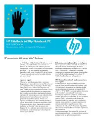
Chapter 2The Grand TourThis chapter identifies the various components of your computer. Become familiarwith each component before you operate the computer.Front with the display closedFigure 2-1 shows the computer’s front with its display panel in the closed position.THE GRAND TOURINFRARED PORTDISPLAY LATCHWIRELESS COMMUNICATION SYSTEM INDICATORSSWITCHFigure 2-1 Front of the computer with the display closedDisplay latchWirelesscommunicationswitchThis latch secures the LCD panel in its closed position.Slide the latch to open the display.Slide this switch toward the right to turn off Wireless LANand Bluetooth functions. Slide it toward the left to turn onthe functions.OnOffCAUTION: Set the switch to off in airplanes and hospitals. Check theWireless communication indicator. It will stop glowing when thewireless communication function is off.2-1
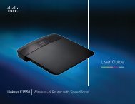
User's ManualTHE GRAND TOURInfrared portSystemindicatorsLeft sideFigure 2-2 shows the computer’s left side.I.LINK PORT SD CARDThis infrared port is compatible with Infrared Data Association(IrDA 1.1) standards. It enables cableless 4 Mbps,1.15 Mbps, 115.2 kbps, 57.6 kbps, 38.4 kbps, 19.2 kbps or9.6 kbps data transfer with IrDA 1.1 compatible externaldevices.LEDs let you monitor the status of various computerfunctions. Details are given in the System indicatorssection.INDICATORSD CARDSLOTVOLUME CONTROLSECURITY LOCKPC CARD LOCK PC CARD SLOT MICROPHONEJACKFigure 2-2 The left side of the computerHEADPHONEJACKSecurity locki.LINK (IEEE1394)portA security cable attaches to this slot. The optional securitycable anchors your computer to a desk or other largeobject to deter theft.Connect an external device, such as a digital video camerato this port for high-speed data transfer.SD card indicatorThis indicator glows green when the computer is accessingthe SD card slot.SD card slot SD cards are used in a wide variety of external devices.This slot lets you transfer data from the device to yourcomputer. An indicator on the left side of the slot glowswhen a card is being accessed.CAUTION: Keep foreign objects out of the SD card slot. A pin or similarobject can damage the computer’s circuitry.2-2
Right sidePC card lockPC card slotCBThis lock prevents removal of a PC card when it is in thelock position and a security card is attached.A PC card slot can accommodate one 5 mm PC card (TypeII). You can install any industry standard PC card such as aSCSI adaptor, Ethernet adaptor or flash memory card.CAUTION: Keep foreign objects out of the PC card slot. A pin or similarobject can damage the computer’s circuitry.Microphone jackHeadphone jackVolume controlA standard 3.5 mm mini microphone jack enables connectionof a monaural microphone or other device for audioinput.A standard 3.5 mm mini headphone jack enables connectionof a stereo headphone (16 ohm minimum) or otherdevice for audio output. When you connect headphones,the internal speaker is automatically disabled.Use this dial to adjust the volume of the stereo speakersand subwoofer or the stereo headphones.THE GRAND TOURRight sideFigure 2-3 shows the computer’s right side.SLIM SELECT BAYFigure 2-3 The right side of the computerSlim Select BayA DVD-ROM drive, CD-RW/DVD-ROM drive, CD-ROMdrive, DVD Multi drive, optional CD-R/RW drive, optionalSlim Select Bay HDD adaptor, optional Slim Select Bay 2ndbattery pack or optional <strong>TOSHIBA</strong> Style Bay Bridge mediaadaptor can be installed in the Slim Select Bay. A weightsaver can be installed when there is no module.2-3
User's ManualBack sideFigure 2-4 shows the computer’s back side.EXTERNALMONITOR PORTPARALLELPORTLAN ACTIVEINDICATOR (ORANGE)LINK INDICATOR(GREEN)THE GRAND TOURDC IN 15VUSBVIDEO-OUT MODEMLANPORTS JACKJACK JACKFigure 2-4 The back side of the computerCOOLINGVENTA single cover protects the external monitor port and parallel port.DC IN 15V The AC adaptor connects to this socket. Use only themodel of AC adaptor that comes with the computer. UsingDC IN 15Vthe wrong adaptor can damage your computer.Universal Two Universal Serial Bus ports are on the left side. TheSerial Bus ports comply with the USB 2.0 standard, which enables(USB 2.0) ports data transfer speeds 40 times faster than the USB 1.1standard. (The ports also support USB 1.1.)CAUTION: Keep foreign objects out of the USB connectors. A pin orsimilar object can damage the computer’s circuitry.NOTE: Operation of all functions of all USB devices has not beenconfirmed. Some functions might not execute properly.Video-out jackExternal monitorportPlug a mini-jack TV adaptor cable into this jack for bothline-out and video-out. The TV adaptor cable carries videoas well as audio data for left and right speakers. Use theTV out Button to turn on and off the TV display.This 15-pin port lets you connect an external videodisplay.2-4
Back sideParallel portThis Centronics-compatible, 25-pin parallel port is used toconnect a parallel printer or other parallel device. This portsupports Extended Capabilities Port (ECP) standard.Modem jackCAUTIONS: 1.In areas where an internal modem is installed as standardequipment, there is a modem jack that lets you use amodular cable to connect the modem directly to a telephoneline.In case of a lightning storm, unplug the modem cablefrom the telephone jack.2. Do not connect the modem to a digital telephone line.A digital line will damage the modem.THE GRAND TOURLAN jackEtherLAN activeindicator (orange)Link indicator(green)Cooling ventThis jack lets you connect to a LAN. The adaptor hasbuilt-in support for Ethernet LAN (10 megabits per second,10BASE-T) and Fast Ethernet LAN (100 megabits persecond, 100BASE-Tx). The LAN has two indicators. SeeChapter 4, Operating Basics, for details.This indicator glows orange when data is being exchangedbetween the computer and the LAN.This indicator glows green when the computer is connectedto a LAN and the LAN is functioning properly.This vent provides an outlet for air pulled through thecomputer by the fan.CAUTION: Be careful not to block the cooling vent. Also be careful tokeep foreign objects out of them. A pin or similar object can damage thecomputer’s circuitry.2-5
User's ManualUndersideFigure 2-5 shows the underside of the computer. Make sure the display is closedbefore turning over your computer.SLIM SELECT BAYDOCKING HOLEDOCKING PORTDOCKING HOLETHE GRAND TOURLATCHSLIM SELECTBAY LOCKBATTERY PACK BATTERY RELEASE LATCH MEMORY MODULE COVERFigure 2-5 The underside of the computerSlim Select Bay Slide this latch to free the Slim Select Bay for removal.latchSlim Select Bay There are two screw holes next to the Slim Select Baylock latch. One screw is initially set in the front hole, which isthe unlock position. To lock the Slim Select Bay latch, setthe screw in the back hole.NOTE: Use a point size 0 Phillips screwdriver.Battery pack The battery pack powers the computer when the ACadaptor is not connected. For detailed information on thebattery pack, refer to Chapter 6, Power and Power-UpModes.Battery release Slide this latch to release the battery pack for removal.latchMemory modulecoverThis cover protects two memory module sockets. One ortwo modules are preinstalled. Refer to the Memoryexpansion section in Chapter 8, Optional Devices.2-6
Front with the display openDocking portUse this port to connect an optional Port Replicator.CAUTION: Keep foreign objects out of the docking port. A pin or similarobject can damage the computer’s circuitry.Docking holesThese holes ensure a proper connection between thecomputer and an optional Port Replicator.Front with the display openThis section shows the computer with the display open. To open the display, slidethe display latch on the front of the display and lift up. Position the display at acomfortable viewing angle.THE GRAND TOURDISPLAY HINGEDISPLAY SCREENINTERNET BUTTONSTEREO SPEAKER(RIGHT)STEREO SPEAKER(LEFT)<strong>TOSHIBA</strong> CONSOLEBUTTONTV OUT BUTTONACCUPOINTPOWER BUTTONCD/DVD PLAYBUTTON*DIGITAL AUDIO PLAYBUTTON*AUDIO/VIDEO TOUCH PADCONTROL BUTTONS*ACCUPOINTCONTROLBUTTONSTOUCH PADCONTROL BUTTONSMICROPHONEFigure 2-6 The front of the computer with the display open2-7
User's ManualTHE GRAND TOURDisplay hingeDisplay screenStereo speakersPower buttonThe display hinge holds the display screen at easy-toviewangles.The LCD displays high-contrast text and graphics. Thecomputer’s LCD consists of up to 1024 x 768 pixels, 1400 x1050 pixels or 1600 x 1200 pixels. Refer to Appendix B.When the computer operates on the AC adaptor thedisplay screen’s image will be somewhat brighter thanwhen it operates on battery power. The lower brightnesslevel is intended to save battery power.The speakers emit sound generated by your software aswell as audio alarms, such as low battery condition,generated by the system.Press the power button to turn the computer’s power onand off.Internet button<strong>TOSHIBA</strong> ConsolebuttonPress this button to launch an Internet browser. If thecomputer’s power is off, you can press this button to turnon the computer’s power and launch the browser automaticallyin one step.Press this button to launch an application automatically.The default is <strong>TOSHIBA</strong> Console.TV out ButtonCD/DVD Playbutton*Digital Audio Playbutton*Press this button to set your display device to TV (Videoout).Press it again to return to LCD.Press this button to directly launch various CD and DVDfunctions. You can also turn on the computer’s power byholding down this button for one second and turn off thepower by holding it down for 0.5 second. Refer to Chapter4, Operating Basics, for details.Press this button to directly launch various digital audiofunctions. You can also turn on the computer’s power byholding down this button for one second. Refer to Chapter4, Operating Basics, for details.Audio/Video Previous button: Plays the previous track/chapter/control buttons* data. Play/pause button: Begins or pauses play. Stopbutton: Halts play. Next button: Plays the nexttrack/chapter/data. Refer to Chapter 4, Operating Basics.2-8
System indicatorsNOTE: If Random is selected in Windows Media Player, selecting Next orPrevious advances to a random selection.* The CD/DVD Play button, Digital Audio Play button and Audio/Videocontrol buttons are provided with some models.Touch PadTouch Padcontrol buttonsAccuPointAccuPointcontrol buttonsMicrophoneA Touch Pad located in the center of the palm rest is usedto control the on-screen pointer. Refer to the Using theTouch Pad section in Chapter 4, Operating Basics.Control buttons below the Touch Pad let you select menuitems or manipulate text and graphics designated by theon-screen pointer.A pointer control device located in the center of thekeyboard is used to control the on-screen pointer. Refer tothe Using the AccuPoint section in Chapter 4, OperatingBasics.Control buttons below the keyboard let you select menuitems or manipulate text and graphics designated by theon-screen pointer.A built-in microphone lets you record sounds into yourapplications. Refer to the Using the microphone section inChapter 4, Operating Basics.THE GRAND TOURSystem indicatorsFigure 2-7 shows the indicators, which light when various computer operations arein progress.W IRELESSCOMMUNICATIONSLIM SELECTDC INPOWERBATTERYDISKBAYFigure 2-7 System indicators2-9
User's ManualTHE GRAND TOURDC INPowerBatteryDiskThe DC IN indicator glows green when DC power issupplied from the AC power adaptor. If the adaptor’soutput voltage is abnormal or if the power supply malfunctions,this indicator flashes orange.The Power indicator glows green when the computer ison. If you select Standby from Shut Down Windows,this indicator flashes orange (one second on, two secondsoff) while the computer shuts down.The Battery indicator shows the condition of thebattery’s charge: Green indicates full charge, orangeindicates battery charging and flashing orange indicates alow battery charge. Refer to Chapter 6, Power and Power-Up Modes.The Disk indicator glows green when the computer isaccessing the built-in hard disk drive.Slim Select BayWirelesscommunicationThe Slim Select Bay indicator glows green when thecomputer is accessing a DVD-ROM drive, CD-RW/DVD-ROM drive, CD-ROM drive, DVD Multi drive, CD-R/RWdrive, Slim Select Bay HDD adaptor, Slim Select Bay 2ndbattery pack or <strong>TOSHIBA</strong> Style Bay Bridge media adaptorin the Slim Select Bay. When the secondary battery is inthe Slim Select Bay, the Slim Select Bay indicator glowsas follows:Green: fully chargedOrange: charging the batteryThe Wireless communication indicator glows orangewhen the Bluetooth/Wireless LAN function is turned on.2-10
Keyboard indicatorsKeyboard indicatorsThe figures below show the positions of the keypad overlay indicators and theCaps Lock indicator.When the F10 key indicator glows, the keypad overlay lets you control the cursor.When the F11 key indicator glows, the keypad overlay lets you enter numbers.ARROW MODEINDICATOR.NUMERIC MODEINDICATORTHE GRAND TOURArrow modeFigure 2-8 Keypad overlay indicatorsWhen the Arrow mode indicator lights green, you canuse the keypad overlay (gray labeled keys) as cursor keys.Refer to the Keypad overlay section in Chapter 5, TheKeyboard.Numeric mode You can use the keypad overlay (gray labeled keys) fornumeric input when the Numeric mode indicator lightsgreen. Refer to the Keypad overlay section in Chapter 5,The Keyboard.When the Caps Lock indicator glows, the keyboard is in all-caps mode.CAPS LOCKINDICATORFigure 2-9 Caps Lock indicatorCaps LockThis indicator glows green when the alphabet keys arelocked in uppercase.2-11
User's ManualUSB diskette driveA 3 1/2" diskette drive accommodates 1.44-megabyte or 720-kilobyte diskettes. Itconnects to the USB port.THE GRAND TOURDISK-IN-USEINDICATORDISKETTE SLOTEJECT BUTTONFigure 2-10 USB diskette driveDisk-In-UseIndicatorDiskette slotEject buttonThis indicator lights when the diskette is being accessed.Insert diskette in this slot.When a diskette is fully seated in the drive, the ejectbutton pops out. To remove a diskette, push in the ejectbutton and the diskette pops out partially for removal.CAUTION: Check the Disk-In-Use indicator when you use the diskettedrive. Do not press the eject button or turn off the computer while the lightis glowing. Doing so could destroy data and damage the diskette or thedrive.NOTES: 1. The external diskette drive should be placed on a flat,horizontal surface when in use. Do not set the drive on anincline greater than 20 o while it is operating.2. Do not set anything on top of the diskette drive.2-12
Slim Select Bay modulesSlim Select Bay modulesThe Slim Select Bay can accommodate the following modules: DVD-ROM drive, CD-RW/DVD-ROM drive, CD-ROM drive, DVD Multi drive, optional CD-R/RW drive,optional Slim Select Bay HDD adaptor, optional Slim Select Bay 2nd battery pack or<strong>TOSHIBA</strong> Style Bay Bridge media adaptor.DVD-ROM drive (Black)EJECT BUTTONEJECT HOLETHE GRAND TOURDVD-IN-USE INDICATORFigure 2-11 The DVD-ROM driveThe full-size DVD-ROM drive module lets you run either 12 cm (4.72") or 8 cm(3.15") CD/DVDs without using an adaptor. It runs DVD-ROMs at maximum 8 speedand CD-ROMs at maximum 24 speed.NOTE: The read speed is slower at the center of a disc and faster at theouter edge.This drive supports the following formats:• DVD-ROM• DVD-Video• CD-DA• CD-Text• Photo CD (single/multi-session) • CD-ROM Mode 1, Mode 2• CD-ROM XA Mode 2 (Form1, Form2) • Enhanced CD (CD-EXTRA)• CD-G (Audio CD only) • Addressing Method 2Eject button Press the eject button to open the drawer partially.DVD-In-Use This indicator lights when a CD/DVD is being accessed.IndicatorEject hole Insert a slender object to open the drawer when the powerto the DVD-ROM drive is off.CAUTION: Check the Slim Select Bay indicator or DVD-In-Useindicator when you use the DVD-ROM drive. Do not press the eject buttonor turn off the computer while the light is glowing. Doing so could damagethe CD/DVD or the drive.2-13
User's ManualTHE GRAND TOURDVD-ROM drives and media are manufactured according to the specifications of sixmarketing regions. When you purchase DVD media, make sure it matches yourdrive, otherwise it will not play properly.Code Region1 Canada, United States2 Japan, Europe, South Africa, Middle East3 Southeast Asia, East Asia4 Australia, New Zealand, Pacific Islands, Central America, SouthAmerica, Caribbean5 Russia, Indian Subcontinent, Africa, North Korea, Mongolia6 ChinaCD-RW/DVD-ROM drive (Black)EJECT BUTTONEJECT HOLE2-14CD-RW/DVD-IN-USE INDICATORFigure 2-12 The CD-RW/DVD-ROM driveThe full-size CD-RW/DVD-ROM drive module lets you record data to rewritableCDs as well as run either 12 cm (4.72") or 8 cm (3.15") CD/DVDs without using anadaptor.NOTE: The read speed is slower at the center of a disc and faster at theouter edge.DVD read 8 speed (maximum)CD read 24 speed (maximum)CD-R write 24 speed (maximum)CD-RW write 10 speed (maximum, high-speed media)This drive supports the following formats:• DVD-ROM• DVD-Video• CD-DA• CD-Text• Photo CD (single/multi-session) • CD-ROM Mode 1, Mode 2• CD-ROM XA Mode 2 (Form1, Form2) • Enhanced CD (CD-EXTRA)• CD-G (Audio CD only) • Addressing Method 2
Slim Select Bay modulesEject buttonCD-RW/DVD-In-UseIndicatorEject holePress the eject button to open the drawer partially.This indicator lights when a CD/DVD is being accessed.Insert a slender object to open the drawer when the powerto the CD-RW/DVD-ROM drive is off.CAUTION: Check the Slim Select Bay indicator or CD-RW/DVD-In-Use indicator when you use the CD-RW/DVD-ROM drive. Do not pressthe eject button or turn off the computer while the light is glowing. Doingso could damage the CD/DVD or the drive.CD-RW/DVD-ROM drives and media are manufactured according to the specificationsof six marketing regions. When you purchase DVD media, make sure itmatches your drive, otherwise it will not play properly.Code Region1 Canada, United States2 Japan, Europe, South Africa, Middle East3 Southeast Asia, East Asia4 Australia, New Zealand, Pacific Islands, Central America, SouthAmerica, Caribbean5 Russia, Indian Subcontinent, Africa, North Korea, Mongolia6 ChinaCD-R describes compact discs that can be written only once. The recorded datacannot be erased or changed.CD-RW describes compact discs that can be recorded more than once. Use either 1,2, or 4 multi speed CD-RW discs or high-speed 4- to 10-speed discs. The writespeed of the high-speed CD-RW discs is maximum 10-speed.Use Drag’n Drop CD to write compact discs.THE GRAND TOURDVD Multi drive (Black)The full-size DVD Multi drive module lets you record data to rewritable CD/DVDs aswell as run either 12 cm (4.72") or 8 cm (3.15") CD/DVDs without using an adaptor.An ATAPI interface controller is used for CD/DVD-ROM operation. When thecomputer is accessing a CD/DVD, an indicator on the drive glows and Slim SelectBay indicator glows.NOTE: The read speed is slower at the center of a disc and faster at theouter edge.2-15
User's ManualTHE GRAND TOURDVD read8 speed (maximum)DVD-R write 1 speedDVD-RW write 1 speedDVD-RAM write 2 speedCD read24 speed (maximum)CD-R write16 speed (maximum)CD-RW write 8 speed (maximum)This drive supports the following formats:• DVD-ROM• DVD-Video• CD-DA• CD-Text• Photo CD (single/multi-session) • CD-ROM Mode1, Mode2• CD-ROM XA Mode2 (Form1, Form2) • Enhanced CD (CD-EXTRA)• CD-G (Audio CD only) • Addressing Method 2DVD Multi drives and disc are manufactured according to the specifications ofsix marketing regions. When you purchase DVD-Video, make sure it matchesyour drive, otherwise it will not play properly.Code Region1 Canada, United States2 Japan, Europe, South Africa, Middle East3 Southeast Asia, East Asia4 Australia, New Zealand, Pacific Islands, Central America,South America, Caribbean5 Russia, Indian Subcontinent, Africa, North Korea, Mongolia6 ChinaNOTE: Use the WinDVD 4 application to view DVD-Video discs.CD-R and DVD-R discs can be written only once. The recorded data cannot beerased or changed.CD-RW discs can be recorded more than once. Use either 1, 2, or 4 multi speed CD-RW discs or high-speed 4- to 10-speed discs. The write speed of the high-speedCD-RW discs is maximum 10-speed.DVD-RW/-RAM discs can be recorded more than once.CD-ROM drive (Black)The full-size, maximum 24 speed CD-ROM drive module lets you run either 12 cm(4.72") or 8 cm (3.15") compact discs without using an adaptor.2-16
Slim Select Bay modulesThis drive supports the following formats:• Photo CD• CD-R (read only)• CD-ROM• CD-Rewritable (read only)• CD-DA• CD-Text• CD-ROM XA Mode 2 (Form1, Form2) • Enhanced CD (CD-EXTRA)NOTE: The physical features of this drive are similar to those of theDVD-ROM drive. Refer to the illustration in the DVD-ROM drive section.CAUTION: Check the Slim Select Bay indicator when you use theCD-ROM drive. Do not press the eject button, disconnect a drive or turnoff the computer while the light is glowing. Doing so could damage theCD or the drive.THE GRAND TOURCD-R/RW drive (Black)An optional full-size CD-R/RW drive module lets you record data to rewritable CDsas well as run either 12 cm (4.72") or 8 cm (3.15") CDs without using an adaptor.NOTE: The read speed is slower at the center of a disc and faster at theouter edge.CD, CD-R read 24 speed (maximum)CD-RW read 14 speed (maximum)CD-R write 8 speed (maximum)CD-RW write 8 speed (maximum)This drive supports the following formats:• Photo CD• CD-R• CD-ROM• CD-Rewritable• CD-DA• CD-Text• CD-ROM XA Mode 2 (Form1, Form2) • Enhanced CD (CD-EXTRA)NOTE: The physical features of this drive are similar to those of theDVD-ROM drive. Refer to the illustration in the DVD-ROM drive section.CAUTION: Check the Slim Select Bay indicator when you use theCD-R/RW drive. Do not press the eject button, disconnect a drive or turnoff the computer while the light is glowing. Doing so could damage theCD or the drive.2-17
User's ManualSlim Select Bay HDD adaptor (Black)You can increase your computer’s data storage capacity by inserting an optional,integrated, 2 1/2" HDD in the Slim Select Bay. Refer to Chapter 8, Optional Devices,for details on inserting a Slim Select Bay HDD adaptor.THE GRAND TOURFigure 2-13 The Slim Select Bay HDD adaptorSlim Select Bay 2nd battery packAn optional battery pack can be inserted in the Slim Select Bay to increase thecomputer’s battery power and operating time. A Slim Select Bay 2nd battery pack iscomposed of a battery pack and an adaptor. For details, refer to the documentationaccompanying the secondary battery pack. Refer to Chapter 8, Optional Devices,for details on inserting a Slim Select Bay 2nd battery pack.Figure 2-14 The Slim Select Bay 2nd battery pack2-18
Slim Select Bay modules<strong>TOSHIBA</strong> Style Bay Bridge media adaptorThree types of memory cards, CompactFlash, Memory Stick and SmartMedia canbe used in the Bridge media adaptor. Refer to Chapter 8, Optional Devices, fordetails on using a <strong>TOSHIBA</strong> Style Bay Bridge media adaptor.MEMORY STICKSLOTCOMPACTFLASHSLOTSMARTMEDIA SLOTTHE GRAND TOURFigure 2-15 The <strong>TOSHIBA</strong> Style Bay Bridge media adaptorWeight saverInserting a weight saver module in the Slim Select Bay lets you reduce the carryingweight of the computer.Figure 2-16 The weight saver2-19
User's ManualAC adaptorTHE GRAND TOURThe AC adaptor converts AC power to DC power and reduces the voltage suppliedto the computer. It can automatically adjust to any voltage from 100 to 240 volts andto a frequency of either 50 or 60 hertz, enabling you to use the computer in almostany country/region.To recharge the battery, simply connect the AC adaptor to a power source and thecomputer. See Chapter 6, Power and Power-Up Modes, for details.Figure 2-17 The AC adaptorNOTE: The computer’s current rating is 4.0 amperes and comes with anAC adaptor rated 4.0 amperes and 60 watts. You can also use anoptional AC adaptor rated 5.0 amperes and 75 watts.CAUTION: Use only the AC adaptor that came with the computer or anapproved optional adaptor. Use of the wrong adaptor could damageyour computer. <strong>TOSHIBA</strong> assumes no liability for any damage in suchcase.2-20
Chapter 3Getting StartedThis chapter provides basic information to get you started using your computer. Itcovers the following topics:❖Setting up your work space — for your health and safetyNOTE: Be sure also to read Instruction Manual for Safety & Comfort.This guide, which is included with the computer, explains productliability.❖❖❖❖❖❖❖Connecting the AC adaptorOpening the displayTurning on the powerStarting up for the first timeTurning off the powerRestarting the computerRestoring the preinstalled software from the <strong>Pro</strong>duct Recovery CD-ROMGETTING STARTEDNOTE: All users should be sure to read the section Starting up for thefirst time.Setting up your work spaceEstablishing a comfortable work site is important for you and your computer. Apoor work environment or stressful work habits can result in discomfort or seriousinjury from repetitive strain to your hands, wrists or other joints. <strong>Pro</strong>per ambientconditions should also be maintained for the computer’s operation. This sectiondiscusses the following topics:❖❖❖❖❖General conditionsPlacement of the computerSeating and postureLightingWork habits3-1
User's ManualGETTING STARTEDGeneral conditionsIn general, if you are comfortable, so is your computer, but read the following tomake sure your work site provides a proper environment.❖❖❖❖❖❖❖❖❖❖Make sure there is adequate space around the computer for proper ventilation.Make sure the AC power cord connects to an outlet that is close to the computerand easily accessible.The temperature should be 5 to 35 degrees Centigrade (41 to 95 degreesFahrenheit) and the relative humidity should be 20 to 80 percent.Avoid areas where rapid or extreme changes in temperature or humidity mayoccur.Keep the computer free of dust, moisture, and exposure to direct sunlight.Keep the computer away from heat sources, such as electric heaters.Do not use the computer near liquids or corrosive chemicals.Some components in the computer, including data storage media, can bedamaged by magnets. Do not place the computer near magnetic objects orbring magnetic objects close to the computer. Be careful of objects, such asstereo speakers, that produce strong magnetic fields during operation. Also, becareful with metal objects, such as bracelets, which can be inadvertentlymagnetized.Do not operate the computer in close proximity to a mobile phone.Leave ample ventilation room for the fan. Do not block the vents.Placement of the computerPosition the computer and peripheral devices to provide comfort and safety.❖❖❖❖Set the computer on a flat surface at a comfortable height and distance. Thedisplay should be no higher than eye level to avoid eye strain.Place the computer so that it is directly in front of you when you work andmake sure you have adequate space to easily operate other devices.Allow adequate space behind the computer to let you freely adjust the display.The display should be angled to reduce glare and maximize visibility.If you use a paper holder, set it at about the same height and distance as thecomputer.3-2
Setting up your work spaceSeating and postureThe height of your chair in relation to the computer and keyboard as well as thesupport it gives your body are primary factors in reducing work strain. Refer to thefollowing tips and to figure 3-1.BELOW EYE LEVELFOOT REST90 O ANGLESGETTING STARTEDFigure 3-1 Posture and positioning of the computer❖❖❖❖Place your chair so that the keyboard is at or slightly below the level of yourelbow. You should be able to type comfortably with your shoulders relaxed.Your knees should be slightly higher than your hips. If necessary, use a footrest to raise the level of your knees to ease pressure on the back of your thighs.Adjust the back of your chair so it supports the lower curve of your spine.Sit straight so that your knees, hips and elbows form approximately 90 degreeangles when you work. Do not slump forward or lean back too far.3-3
User's ManualLighting<strong>Pro</strong>per lighting can improve legibility of the display and reduce eye strain.❖❖❖Position the computer so that sunlight or bright indoor lighting does not reflectoff the screen. Use tinted windows, shades or other screen to eliminate sunglare.Avoid placing the computer in front of bright light that could shine directly inyour eyes.If possible, use soft, indirect lighting in your computer work area. Use a lampto illuminate your documents or desk, but be sure to position the lamp so that itdoes not reflect off the display or shine in your eyes.GETTING STARTEDWork habitsA key to avoiding discomfort or injury from repetitive strain is to vary youractivities. If possible, schedule a variety of tasks into your work day. If you mustspend long periods at the computer, finding ways to break up the routine can reducestress and improve your efficiency.❖❖❖❖❖❖Sit in a relaxed posture. Good positioning of your chair and equipment asdescribed earlier can reduce tension in your shoulders or neck and ease backstrain.Vary your posture frequently.Occasionally stand up and stretch or exercise briefly.Exercise and stretch your wrists and hands a number of times during the day.Frequently, look away from the computer and focus your eyes on a distantobject for several seconds, for example 30 seconds every 15 minutes.Take frequent short breaks instead of one or two long breaks, for example, twoor three minutes every half hour.❖ Have your eyes examined regularly and visit a doctor promptly, if you suspectyou might be suffering from a repetitive strain injury.A number of books are available on ergonomics and repetitive strain injury orrepetitive stress syndrome. For more information on these topics or for pointers onexercises for such stress points as hands and wrists, please check with your libraryor book vendor. Also refer to the computer’s Instruction Manual for Safety &Comfort.3-4
Connecting the AC adaptorConnecting the AC adaptorAttach the AC adaptor when you need to charge the battery or you want to operatefrom AC power. It is also the fastest way to get started, because the battery packwill need to be charged before you can operate from battery power.The AC adaptor can be connected to any power source supplying from 100 to 240volts and 50 or 60 hertz. For details on using the AC adaptor to charge the batterypack, refer to Chapter 6, Power and Power-Up Modes.NOTE: The computer’s current rating is 4.0 amperes and comes with anAC adaptor rated 4.0 amperes and 60 watts. You can also use an optionalAC adaptor rated 5.0 amperes and 75 watts.CAUTION: Use only the AC adaptor that came with the computer or anapproved optional adaptor. Use of the wrong adaptor could damage yourcomputer. <strong>TOSHIBA</strong> assumes no liability for any damage in such case.1. Connect the power cord to the AC adaptor.GETTING STARTEDFigure 3-2 Connecting the power cord to the AC adaptor2. Connect the AC adaptor’s DC output plug to the DC IN socket on the back ofthe computer.Figure 3-3 Connecting the adaptor to the computer3-5
User's Manual3. Plug the power cord into a live wall outlet. The Battery and DC IN indicatorson the front of the computer should glow.Opening the displayThe display panel can be rotated in a wide range of angles for optimal viewing.1. Slide the display latch on the front of the computer to the right.2. Lift the panel up and adjust it to the best viewing angle for you.CAUTION: Use reasonable care when opening and closing the displaypanel. Opening it vigorously or slamming it shut could damage thecomputer.DISPLAY LATCHGETTING STARTEDFigure 3-4 Opening the displayTurning on the powerThis section describes how to turn on the power.NOTE: After you turn on the power for the first time, do not turn it offuntil you have set up the operating system. Refer to the section Starting upfor the first time in this chapter.1. Open the display.3-6
Turning off the power2. Press and hold the computer’s power button for two or three seconds.Figure 3-5 Turning on the powerStarting up for the first timeWhen you first turn on the power, the computer’s initial screen is the MicrosoftWindows XP <strong>Pro</strong>fessional or Windows 2000 Startup Screen Logo.Follow the on-screen directions.Turning off the powerGETTING STARTEDThe power can be turned off in one of the following modes: Shut down (Boot),Hibernation or Standby mode.Shut down mode (Boot mode)When you turn off the power in boot mode, no data is saved and the computer willboot to the operating system’s main screen.1. If you have entered data, save it to the hard disk or to a diskette.2. Make sure all disk (disc) activity has stopped, then remove any CD/DVDs ordiskette.CAUTION: Make sure the Disk, Slim Select Bay and Slim SelectBay’s module indicators are off. If you turn off the power while a disk(disc) is being accessed, you can lose data or damage the disk (disc).3. a. In Windows XP, click start then click Turn off computer. From theTurn off computer menu select Turn off.3-7
User's Manualb. In Windows 2000, click Start and click Shut Down. From the ShutDown menu select Shut Down.4. Turn off the power to any peripheral devices.CAUTION: Do not turn the computer or devices back on immediately.Wait a moment to let all capacitors fully discharge.Hibernation modeThe hibernation feature saves the contents of memory to the hard disk when thecomputer is turned off. The next time the computer is turned on, the previous stateis restored. The hibernation feature does not save the status of peripheral devices.GETTING STARTEDCAUTIONS: 1. While entering hibernation mode, the computer savesthe contents of memory to the HDD. Data will be lost ifyou remove the battery or disconnect the AC adaptorbefore the save is completed. Wait for the Diskindicator to go out.2. Do not install or remove a memory module while thecomputer is in hibernation mode. Data will be lost.Benefits of hibernationThe hibernation feature provides the following benefits:❖Saves data to the hard disk when the computer automatically shuts downbecause of a low battery.NOTE: For the computer to shut down in hibernation mode, the hibernationfeature must be enabled in two places in <strong>TOSHIBA</strong> Power Saver: theHibernate window and the Battery Alarm item of the Alarm window.Otherwise, the computer will shut down in Standby mode. If battery powerbecomes depleted, data saved in Standby will be lost.❖❖You can return to your previous working environment immediately when youturn on the computer.Saves power by shutting down the system when the computer receives no inputor hardware access for the duration set by the System hibernate feature.3-8
Turning off the power❖You can use the panel power off feature.Starting HibernationTo enter Hibernation mode, follow the steps below.Windows XP1. Click start.2. Select Turn Off Computer.3. Open the Turn Off Computer dialog box. Hibernate is not displayed.4. Press the Shift key. The Standby item will change to Hibernate.5. Select Hibernate.Windows 20001. Click Start and click Shut Down.2. From the Shut Down menu select Hibernate and click the OK button.Automatic HibernationThe computer will enter Hibernate mode automatically when you press the powerbutton or close the lid. First, however, make the appropriate settings according tothe steps below.1. Open the Control Panel.2. a. In Windows XP, open Performance and Maintenance and open<strong>TOSHIBA</strong> Power Saver.b. In Windows 2000, double-click the <strong>TOSHIBA</strong> Power Saver icon.3. Select the Hibernate window, select the Enable Hibernate support checkbox and click the Apply button.4. Select the Power Save Modes window.5. Double-click Power Mode (Full Power, Normal, etc.) and open theSystem Power Mode window.6. Enable the desired Hibernation settings for When I press the powerbutton and When I close the lid.7. Click the OK button.GETTING STARTED3-9
User's ManualData save in hibernation modeWhen you turn off the power in hibernation mode, the computer takes a moment tosave current memory data to the hard disk. During this time, the Disk indicator willlight.After you turn off the computer and memory is saved to the hard disk, turn off thepower to any peripheral devices.CAUTION: Do not turn the computer or devices back on immediately.Wait a moment to let all capacitors fully discharge.Standby modeIn standby mode the power remains on, but the CPU and all other devices are insleep mode.GETTING STARTEDCAUTIONS: 1. Before entering Standby mode, be sure to save your data.2. Do not install or remove a memory module while thecomputer is in standby mode. The computer or themodule could be damaged.3. Do not remove the battery pack while the computer is instandby mode (unless the computer is connected to an ACpower source). Data in memory will be lost.4. If you carry the computer on board an aircraft or into ahospital, be sure to shut down the computer in hibernationmode or in shutdown mode to avoid radio signalinterference.Benefits of standbyThe standby feature provides the following benefits:❖❖❖Restores the previous working environment more rapidly than does hibernation.Saves power by shutting down the system when the computer receives no inputor hardware access for the duration set by the System Standby feature.You can use the panel power off feature.3-10
Turning off the powerExecuting standbyNOTE: You can also enable Standby by pressing Fn + F3. See Chapter5, The Keyboard for details.You can enter standby mode in one of three ways:1. a. In Windows XP, click start, click Turn Off Computer and clickStand by.b. In Windows 2000, click Start, click Shut Down, select Stand by andclick OK.2. Close the display panel. This feature must be enabled. Refer to the SystemPower Mode item in Power Saver Utility described in the Control Panel.a. In Windows XP, open Performance and Maintenance and open<strong>TOSHIBA</strong> Power Saver.b. In Windows 2000, double-click the <strong>TOSHIBA</strong> Power Saver icon.3. Press the power button. This feature must be enabled. Refer to the SystemPower Mode item in Power Saver Utility described in the Control Panel.a. In Windows XP, open Performance and Maintenance and open<strong>TOSHIBA</strong> Power Saver.b. In Windows 2000, double-click the <strong>TOSHIBA</strong> Power Saver icon.When you turn the power back on, you can continue where you left when you shutdown the computer.GETTING STARTEDNOTES: 1. When the computer is shut down in standby mode, thePower indicator glows orange.2. If you are operating the computer on battery power, youcan lengthen the operating time by shutting down inhibernation mode. Standby mode consumes more power.Standby limitationsStandby will not function under the following conditions:❖❖Power is turned back on immediately after shutting down.Memory circuits are exposed to static electricity or electrical noise.3-11
User's ManualRestarting the computerGETTING STARTEDCertain conditions require that you restart the computer system. For example, if:❖You change certain computer settings.❖ An error occurs and the computer does not respond to your keyboardcommands.There are two ways to restart the computer system:1. a. In Windows XP, click start then click Turn off computer. From theTurn off computer menu select Restart.b. In Windows 2000, click Start and click Shut Down. From the ShutDown menu select Restart.2. Press the power button and hold it down for five seconds. Wait 10 to 15seconds, then turn the power on again by pressing the power button.Restoring the preinstalled softwarefrom the <strong>Pro</strong>duct Recovery CD-ROMIf preinstalled files are damaged, use the <strong>Pro</strong>duct Recovery CD-ROM to restorethem. To restore the operating system and all preinstalled software, follow the stepsbelow.CAUTION: When you reinstall the Windows operating system, the harddisk will be reformatted and all data will be lost.1. Load the <strong>Pro</strong>duct Recovery CD-ROM in the optional optical media drive andturn off the computer’s power.2. Hold down the F12 key and turn on the power. When In Touch withTomorrow <strong>TOSHIBA</strong> appears, release the F12 key.3. Use the left or right cursor key to select the CD-ROM icon in the displaymenu. For details, refer to the Boot Priority section in Chapter 7, HW Setup.4. Follow the on-screen instructions.3-12
Chapter 4Operating BasicsThis chapter gives information on basic operations including using the <strong>TOSHIBA</strong>Dual Pointing Device, USB diskette drive, optical media drives, the microphone, theinternal modem, wireless communication, LAN and changing Slim Select Baymodules. It also provides tips on caring for your computer, diskettes and CD/DVDs.<strong>TOSHIBA</strong> Dual Pointing DeviceThe computer is equipped with a dual point system: a Touch Pad and an AccuPointpointing stick.TOUCH PADACCUPOINTACCUPOINTCONTROLBUTTONSTOUCH PADCONTROLBUTTONSOPERATING BASICSFigure 4-1 Touch Pad, AccuPoint and control buttons4-1
User's ManualUsing the Touch PadTo use the Touch Pad, simply touch and move your finger tip across it in thedirection you want the on-screen pointer to go.Two buttons below the Touch Pad are used like the buttons on a mouse pointer.Press the left button to select a menu item or to manipulate text or graphics designatedby the pointer. Press the right button to display a menu or other functiondepending on the software you are using.NOTE: You can also tap the Touch Pad to perform functions similar tothose of the left button.Click: Tap the Touch Pad onceDouble click: Tap twiceDrag and drop: Tap to select the material you want to move. Leave yourfinger on the Touch Pad after the second tap and move the material.OPERATING BASICSUsing the AccuPointTo use the AccuPoint, simply push it with your finger tip in the direction you wantto move the on-screen pointer.Two buttons above the Touch Pad work in the same way with the AccuPoint asthey do with the Touch Pad. Refer to the Using the Touch Pad section for details.AccuPoint precautionsCertain conditions can affect the on-screen pointer when using AccuPoint. Forexample, the pointer may travel contrary to AccuPoint operation or an error messagemay appear, if❖❖❖You touch the AccuPoint during power-up.You apply constant, soft pressure during power-up.There is a sudden temperature change.❖ Strong stress is applied to the AccuPoint.If an error message appears, reboot the computer. If an error message does notappear, wait a moment for the pointer to stop, then continue operation.4-2
Using the USB diskette driveReplacing the capThe AccuPoint cap is an expendable item that should be replaced after prolongeduse. This is one spare AccuPoint cap supplied with the computer.1. To remove the AccuPoint cap, firmly grasp the cap and pull it straight up.ACCUPOINT CAPPEGFigure 4-2 Removing the AccuPoint cap2. Position a new cap on the peg and press it into place.NOTE: The peg is square, so be careful to align the cap’s square holewith the peg.Using the USB diskette driveOPERATING BASICSA 3 1/2" diskette drive connects to the computer’s USB port. It accommodates 1.44-megabyte or 720-kilobyte diskettes. Refer to Chapter 2, The Grand Tour, for moreinformation.4-3
User's ManualConnecting 3 1/2" diskette driveTo connect the drive, plug the diskette drive connector into a USB port. Refer toFigure 4-3.CAUTION: Make sure the connector is right side up and properlyaligned with the socket. Do not try to force the connection, doing so candamage the connecting pins.Figure 4-3 Connecting the USB diskette driveOPERATING BASICSNOTE: If you connect the diskette drive after turning on the computer, itwill take about 10 seconds for the computer to recognize the drive. Donot disconnect and reconnect before 10 seconds has elapsed.Disconnecting 3 1/2" diskette driveWhen you have finished using the diskette drive, follow the procedures below todisconnect it:1. Wait for the indicator light to go out to make sure all diskette activity hasstopped.CAUTION: If you disconnect the diskette drive or turn off the powerwhile the computer is accessing the drive you may lose data or damagethe diskette or the drive.2. a. In Windows XP, open the Safety Remove Hardware icon on thesystem tray.b. In Windows 2000, open the Unplug or Eject Hardware icon on thesystem tray.4-4
Changing Slim Select Bay modules3. Click Diskette drive.4. Pull the diskette drive connector out of the USB port.Changing Slim Select Bay modulesThis section explains how to change modules in the Slim Select Bay. The illustrationsshow replacement of the DVD-ROM drive with the Slim Select Bay HDDadaptor. Therefore, the text refers to those modules. However, the procedures arethe same for any of the modules: CD-RW/DVD-ROM drive, CD-ROM drive, DVDMulti drive, CD-R/RW drive, Slim Select Bay 2nd battery pack, <strong>TOSHIBA</strong> Style BayBridge media adaptor with separate tray or weight saver.CAUTIONS: 1. To avoid injury, do not put your hand into the SlimSelect Bay slot.2. Before removing or inserting a second battery pack,turn off the computer’s power.NOTE: The <strong>TOSHIBA</strong> Mobile Extension is preinstalled to support hotswapping under Windows. Refer to Chapter 1, Introduction, for informationon using this utility to change modules while the computer’s poweris on. If you are using a Bridge media adaptor, you can click theWindows Safety Remove Hardware icon on the System tray (Task Bar) toremove the Bridge media adaptor.Removing a moduleRemove the DVD-ROM drive as described below.1. Check all disc indicators to make sure no discs are operating.2. Turn the computer upside down.OPERATING BASICSCAUTION: Wait for all disc indicators to go out before you turn over thecomputer and be careful to lay the computer down gently. Shock candamage the HDD or other components.3. Remove the screw near the icon securing the Slim Select Bay.4. Make sure the screw in the Slim Select Bay lock is set in the hole for the unlockposition.5. Slide the Slim Select Bay latch to the unlock position.4-5
User's Manual6. Grasp the DVD-ROM drive and slide it out.CAUTION: The DVD-ROM drive and other Slim Select Bay modules canbecome hot with use. Be careful when removing the module.SLIM SELECT BAYMODULESLIM SELECT BAYLATCHFigure 4-4 Removing the DVD-ROM driveOPERATING BASICSInserting a moduleInsert the Slim Select Bay HDD adaptor as described below.1. Insert the Slim Select Bay HDD adaptor in the computer as shown below andpress until the ejector clicks.2. If you want to lock the Slim Select Bay module, set the screw of the Slim SelectBay lock in the back hole.SLIM SELECT BAYMODULESCREWSLIM SELECTBAY LOCKFigure 4-5 Inserting the Slim Select Bay HDD adaptor4-6
Using optical media drivesUsing optical media drivesThe text and illustrations in this section refer primarily to the DVD-ROM drive.However, operation is the same for the CD-RW/DVD-ROM, CD-ROM, DVD Multiand optional CD-R/RW drives. The full-size drive provides high-performanceexecution of CD/DVD-ROM-based programs. You can run either 12 cm (4.72") or 8cm (3.15") CD/DVDs without an adaptor. An ATAPI interface controller is used forCD/DVD-ROM operation. When the computer is accessing a CD/DVD-ROM, anindicator on the drive glows and the Slim Select Bay indicator glows.NOTE: Use the WinDVD 4 application to view DVD-Video discs.If you have a CD-RW/DVD-ROM drive, refer also to the Writing CDs on CD-RW/DVD-ROM drive or Writing CD/DVDs on DVD Multi drive sections for precautionson writing to CD/DVDs.Loading discsTo load CD/DVDs, follow the steps below and refer to figures 4-6 to 4-10.1. a. When the power is on, press the DVD-ROM eject button to open thedrawer slightly.OPERATING BASICSEJECT BUTTONFigure 4-6 Pressing the DVD-ROM eject button4-7
User's Manualb. Pressing the eject button will not open the drawer when the DVD-ROMdrive’s power is off. If the power is off, you can open the drawer byinserting a slender object (about 15 mm) such as a straightened paper clipinto the eject hole just to the right of the eject button.15mmDiameter 1.0mmFigure 4-7 Manual release with the eject hole2. Grasp the drawer gently and pull until it is fully opened.OPERATING BASICSFigure 4-8 Pulling the drawer open4-8
Using optical media drives3. Lay the CD/DVD, label side up, in the drawer.Figure 4-9 Inserting a CD/DVDNOTE: When the drawer is fully opened, the edge of the computer willextend slightly over the CD/DVD tray. Therefore, you will need to turnthe CD/DVD at an angle when you place it in the tray. After seating theCD/DVD, however, make sure it lies flat, as shown in figure 4-9.CAUTIONS: 1. Do not touch the laser lens. Doing so could causemisalignment.2. Be careful to keep foreign matter from entering thedrive. Check the back edge of the tray to make sure itcarries no debris before closing the drive.OPERATING BASICS4. Press gently at the center of the CD/DVD until you feel it click into place. TheCD/DVD should lie below the top of the spindle, flush with the spindle base.4-9
User's Manual5. Push the center of the drawer to close it. Press gently until it locks into place.CAUTION: If the CD/DVD is not seated properly when the drawer isclosed, the CD/DVD might be damaged. Also, the drawer might not openfully when you press the eject button.Figure 4-10 Closing the DVD-ROM drawerOPERATING BASICSRemoving discsTo remove the CD/DVD, follow the steps below and refer to figure 4-11.CAUTION: Do not press the eject button while the computer is accessingthe DVD-ROM drive. Wait for the DVD-In-Use indicator to go out beforeyou open the drawer. Also, if the CD/DVD is spinning when you open thedrawer, wait for it to stop before you remove it.1. To pop the drawer partially open, press the eject button. Gently pull thedrawer out until it is fully opened.CAUTIONS: 1. When the drawer pops open slightly, wait a moment tomake sure the CD/DVD has stopped spinning beforepulling the drawer fully open.2. Turn off the power before you use the eject hole. If theCD/DVD is spinning when you open the drawer, theCD/DVD could fly off the spindle and cause injury.4-10
Using optical media drives2. The CD/DVD extends slightly over the sides of the drawer so you can grasp it.Hold the CD/DVD gently and lift it out.Figure 4-11 Removing a CD/DVD3. Push the center of the drawer to close it. Press gently until it locks into place.CD/DVD Play, Digital Audio Play buttonsThis section describes how to use the CD/DVD Play button or the Digital AudioPlay button to control the CD/DVD-ROM drive, Digital Audio Data.NOTE: You can turn on the computer’s power by holding down theDigital Audio Play button for one second. When you use only the CDplayer, while the computer is off, you can turn the power off by pressingthe CD/DVD Play button for 0.5 second. Pressing the Digital Audio Playbutton will not turn off the power.OPERATING BASICS4-11
User's ManualCD/DVD Play buttonDigital Audio Play buttonPower is off If an audio CD is in the drive, Operating system starts,the system enters CD Player Windows Media Playermode and operates as a starts and Digital Audiostand-alone CD player. Data play begins.If a DVD-Video disc is in thedrive, the operating systemstarts and the DVD-Videoplayer starts.CD player DVD-ROM drive power Operating system starts,mode turns off. Windows Media Playerstarts and Digital AudioData play begins.OPERATING BASICSOS is running If an audio CD is in the drive,Windows Media Playerstarts and CD audio playbegins.If a DVD-Video disc is in thedrive, the DVD-Video playerstarts and DVD-Video playbegins.The CD/DVD icon isdisplayed in the WindowsTask Bar.Windows Media Playerstarts and Digital AudioData play begins.The Digital Audio icon isdisplayed in the Task Bar.NOTES: 1. To play Digital Audio Data, you must set the play list in theWindows Media Player. The next time you play DigitalAudio Data in succession, the former play list will becomeactive. If a CD was played the previous time, then All Audiowill be used.2. When the computer system power is off, if no control buttonis activated within four minutes of turning on the DVD-ROM drive power, power to the drive will automatically beturned off. In this case, press the CD/DVD Play buttonagain to turn on the power.CAUTION: Do not install or remove a memory module while the DVD-ROM drive power is on. First turn off the power to the DVD-ROM drive.4-12
Writing CDs on CD-RW/DVD-ROM driveAudio/Video control buttonsBesides the power button, the following four buttons control functions of theDVD-ROM drives and Digital Audio Data:1. Play/Pause Starts or pauses play2. Stop Stops play3. Next Advances to the next track, chapter or data4. Previous Returns to the previous track, chapter or dataNOTE: If Random or Shuffle is selected in Windows Media Player,selecting Next or Previous advances to a random selection.Writing CDs on CD-RW/DVD-ROMdriveDepending on the type of drive installed, you may be able to write CDs. TheCD-RW/DVD-ROM drive lets you write as well as read CD-ROMs. Observe theprecautions in this section to ensure the best performance for writing CDs. Forinformation on loading and unloading CDs refer to the Using optical media drivesection.NOTE: CD-R discs can be written to only once. CD-RW discs can berewritten many times.Before writing or rewritingPlease observe the following points when you write or rewrite the data.❖We recommend the following manufacturers of CD-R and CD-RW media.Media quality can affect write or rewrite success rates.CD-R:TAIYOYUDEN CO., LTD.Mitsui Chemicals Inc.MITUBISHI CHEMICAL CORPORATIONRICOH Co., Ltd.Hitachi Maxell Ltd.CD-RW: MITUBISHI CHEMICAL CORPORATIONRICOH Co., Ltd.<strong>TOSHIBA</strong> has confirmed the operation of CD-R and CD-RW media of the manufacturersabove. Operation of other media cannot be guaranteed.OPERATING BASICS4-13
User's Manual❖❖❖❖❖❖❖❖❖CD-RW can generally be rewritten about 1,000 times. However, the actualnumber of rewrites is affected by the quality of the media and the way it isused.Be sure to connect the AC adaptor when you write or rewrite.Be sure to close all other software programs except the writing software.Do not run software such as a screen saver which can put a heavy load on theCPU.Operate the computer at full power. Do not use power-saving features.Do not write while virus check software is running. Wait for it to finish, thendisable virus detection programs including any software that checks filesautomatically in the background.Do not use hard disk utilities, including those intended to enhance HDDaccess speed. They may cause unstable operation and damage data.Write from the computer’s HDD to the CD. Do not try to write from shareddevices such as a LAN server or any other network device.Writing with software other than Drag’n Drop CD has not been confirmed.Therefore, operation with other software cannot be guaranteed.OPERATING BASICSWhen writing or rewritingNote the following when you write or rewrite a CD-R or CD-RW.❖❖❖Always copy data from the HDD to the CD. Do not use cut-and-paste. Theoriginal data will be lost if there is a write error.Do not perform any of the following actions:• Operate the computer for any other function, including use of a mouse orTouch Pad, closing/opening the LCD panel.• Start a communication application such as a modem.• Apply impact or vibration to the PC.• Install, remove or connect external devices, including the following:PC card, SD card, USB devices, external display, i.LINK devices, opticaldigital devices.• Use the CD/MP3 control buttons to reproduce music and voice.• Open the optical media drive.If the media is poor in quality, dirty or damaged, writing or rewriting errors mayoccur.4-14
Writing CD/DVDs on DVD Multi drive❖❖Set the computer on a level surface and avoid places subject to vibration suchas airplanes trains, or cars. Do not use an unstable surface such as a stand.Keep mobile phones and other wireless communication devices away from thecomputer.Writing CD/DVDs on DVD Multi driveYou can use the DVD Multi drive to write data to either CD-R/RW or DVD-R/-RW/-RAM discs. The following applications for writing are supplied on CD-ROM:Drag’n Drop CD, licensed by Easy Systems Japan Ltd., and DigiOn Inc., MotionDVSTUDIO, DVDfunSTUDIO and DVD-MovieAlbum, licensed by Matsushita ElectricIndustrial Co.,Ltd.Important messageBefore you write or rewrite to CD-R/RW or DVD-R/-RW/-RAM disc, read andfollow all set-up and operating instructions in this section. If you fail to do so, theDVD Multi drive may not function properly, and you may fail to write or rewrite,lose data or incur other damage.Disclaimer<strong>TOSHIBA</strong> does not bear responsibility for the following:❖❖Damage to any CD-R/RW or DVD-R/-RW/-RAM disc that may be caused bywriting or rewriting with this product.Any change or loss of the recorded contents of CD-R/RW or DVD-R/-RW/-RAM disc that may be caused by writing or rewriting with this product, or forany business profit loss or business interruption that may be caused by thechange or loss of the recorded contents.❖ Damage that may be caused by using third party equipment or software.Given the technological limitations of current optical disc writing drives, you mayexperience unexpected writing or rewriting errors due to disc quality or problemswith hardware devices. Also, it is a good idea to make two or more copies ofimportant data, in case of undesired change or loss of the recorded contents.OPERATING BASICS4-15
OPERATING BASICS4-16User’s ManualRead/write function chart : Yes × : NoDisc type CD-R CD-RW DVD-R DVD-RW DVD-RAM DVD+R DVD+RWRead × ×Write × ×Drag’n Drop CD*1 × × ×DVDfunSTUDIO*1 × × × × ×DVD-MovieAlbum*1 × × × × × ×DVD-Video*2 × × × × ×DVD VR*2(DVD Video Recording) × × × × × ×User's ManualOPERATING BASICS*1 Software supplied with the product can be used for writing to a disc.*2 Video format can be written.4-16
Writing CD/DVDs on DVD Multi drive❖❖❖❖❖❖❖❖❖Based on <strong>TOSHIBA</strong>’s limited compatibility testing, we suggest the followingmanufacturers of CD-R/RW and DVD-R/-RW/-RAM disc. However, in noevent does <strong>TOSHIBA</strong> guarantee the operation, quality or performance of anydisc. Disc quality can affect write or rewrite success rates.CD-R: TAIYOYUDEN CO., LTD.Mitsui Chemicals Inc.MITSUBISHI CHEMICAL CORPORATIONRICOH Co., Ltd.Hitachi Maxell Ltd.CD-RW: MITSUBISHI CHEMICAL CORPORATIONRICOH Co., Ltd.DVD-R: DVD Specifications for Recordable Disc for General Version 2.0TAIYOYUDEN CO., LTD.PIONEER VIDEO CORPORATIONMITSUBISHI CHEMICAL CORPORATIONDVD-RW: DVD Specifications for Re-recordable Disc for Version 1.1VICTOR COMPANY OF JAPAN LIMITEDTDK CorporationDVD-RAM:DVD Specifications for DVD-RAM Disc for Version 2.0 or Version2.1Matsushita Electric Industrial Co., Ltd.If the disc is poor in quality, dirty or damaged, writing or rewriting errors mayoccur. Be careful to check the disc for dirt or damage before you use it.The actual number of rewrites to CD-RW or DVD-RW/-RAM is affected by thequality of the disc and the way it is used.There are two types of DVD discs: authoring and general use discs. Do notuse authoring discs. Only general use discs can be written to by a computerdrive.You can use DVD-RAM discs that can be removed from a cartridge and DVD-RAM discs designed without a cartridge. You cannot use a disc with a 2.6 GBsingle-sided capacity or 5.2 GB double-sided capacity.Other DVD-ROM drives for computers or other DVD players may not be ableto read DVD-R/-RW discs.You cannot add data to a DVD-R/-RW disc that has previously been written to.You cannot overwrite data that has been previously written to a DVD-RW disc.You cannot partially delete any data written to a DVD-RW disc.OPERATING BASICS4-17
User's Manual❖❖❖❖❖❖Data written to a CD-R/DVD-R disc cannot be deleted either in whole or in part.Data deleted (Erase) from a CD-RW and DVD-RW/-RAM disc cannot berecovered. Check the content of the disc carefully before you delete it. Ifmultiple drives that can be written to are connected, be careful not to deletedata from the wrong drive.In writing to a DVD-R/-RW disc, some disc space is required for file management,so you may not be able to write the full capacity of the disc.Since the disc is based on the DVD standard, it will be filled with dummy data ifthe written data is less than about 1 GB. Even if you write only a small amountof data, it will take time to fill in the dummy data.Two types of DVD-R/-RW/-RAM discs are on the market: data and video. Usea video disc to store video data. You can use video discs on a DVD recorder aswell as on your computer’s DVD-ROM drive. You cannot use data discs on aDVD recorder.DVD-RAM formatted by FAT32 cannot be read in Windows 2000 withoutDVD-RAM Driver Software.OPERATING BASICSBefore writing or rewritingPlease observe the following points when you write or rewrite data.❖❖❖❖❖❖❖❖When multiple drives that can be written are connected, be careful not to writeto the wrong drive.Be sure to connect the AC adaptor before you write or rewrite.Before you enter standby/hibernation mode, be sure to finish DVD-RAMwriting. Writing is finished if you can eject DVD-RAM media.Be sure to close all other software programs except the writing software.Do not run software such as a screen saver, which can put a heavy load on theCPU.Operate the computer in the full-power mode. Do not use power-savingfeatures.Do not write while virus check software is running. Wait for it to finish, thendisable virus detection programs including any software that checks filesautomatically in the background.Do not use hard disk utilities, including those intended to enhance HDDaccess speed. They may cause unstable operation and data damage.4-18
Writing CD/DVDs on DVD Multi drive❖❖Write from the computer’s HDD to the CD/DVD. Do not try to write fromshared devices such as a LAN server or any other network device.Writing with software other than Drag’n Drop CD, DVDfunSTUDIO and DVD-MovieAlbum is not recommended.When writing or rewritingPlease observe/consider the following when you write or rewrite to a CD-R/RW orDVD-R/-RW/-RAM disc.❖❖❖❖❖❖Do not perform any of the following actions when writing or rewriting:• Operate the computer for any other function, including using a mouse orTouch Pad or closing/opening the LCD panel.• Start a communication application such as a modem.• Apply impact or vibration to the computer.• Install, remove or connect external devices, including the following:PC card, SD card, USB devices, external display, i.LINK devices, opticaldigital devices.• Use the Audio/Video control button to reproduce music or voice.• Open the DVD Multi driveDo not use standby/hibernation while you write or rewrite.Make sure writing or rewriting is completed before going into standby/hibernation. Writing is completed if you can open the DVD Multi drive tray.Set the computer on a level surface and avoid places subject to vibration suchas airplanes, trains, or cars. Do not use an unstable surface such as a stand.Keep mobile phones and other wireless communication devices away from thecomputer.Always copy data from the HDD to the DVD-RAM. Do not use cut-and-paste.The original data will be lost if there is a write error.OPERATING BASICSDrag’n Drop CDNote the following limitations when you use Drag’n Drop CD:❖ DVD-Video cannot be created using Drag’n Drop CD.❖ DVD-Audio cannot be created using Drag’n Drop CD.4-19
User's Manual❖❖❖❖❖❖❖You cannot use Drag’n Drop CD’s music CD function to record music to aDVD-R/-RW disc.Do not use the DISC Backup function of Drag’n Drop CD to copy DVD-Videoand DVD-ROM with copyright protection, because the copy will not playcorrectly.DVD-RAM disc cannot be backed up with the DISC Backup function of Drag’nDrop CD.You cannot backup a CD-ROM or CD-R/RW to DVD-R/-RW using the DISCBackup function of Drag’n Drop CD.You cannot back up DVD-ROM, DVD-Video or DVD-R/-RW to CD-R/RWusing the DISC Backup function of Drag’n Drop CD.Drag’n Drop CD cannot record in packet format.You might not be able to use the DISC backup function of Drag’n Drop CD toback up a DVD-R/-RW disc that was made with other software on a differentDVD-R/-RW recorder.OPERATING BASICSData verificationTo verify that data is written or rewritten correctly, follow the steps below beforeyou write or rewrite a Data CD/DVD.1. Right-click Data BOX and select Options to display the DATA DISCOption window.2. Mark the Record and Verify check box and select Byte compare.3. Click the OK button.The “Record and Verify” function automatically checks whether data has beencorrectly recorded onto a CD/DVD. “Byte compare” compares the original data filewith the data recorded on the CD/DVD and checks that the data completelymatches.Video (DVD-R/-RW/-RAM)Note the following limitations when you write video to DVD:❖ When installing, uninstalling or MotionDV STUDIO, DVDfunSTUDIO or DVD-MovieAlbum, the computer should be set to system administrator or equivalentprivilege.❖ Whether MotionDV STUDIO and DVD-MovieAlbum use NTSC or PAL formatis determined when the application is installed. To change the format, you willhave to reinstall MotionDV STUDIO and DVD-MovieAlbum.4-20
Writing CD/DVDs on DVD Multi drive❖❖❖❖❖❖❖❖❖❖❖❖❖❖❖When Drag’n Drop or similar software is resident in the computer’s memory,the DVD Multi drive locks. In this situation, other software cannot be used towrite data to the disc.While you are editing DVD-R/-RW/-RAM, you can display previews. However,if an application other than WinDVD is running, the preview might notdisplay properly. To ensure proper display of previews, do not start otherapplications while you are editing DVD-R/-RW/-RAM disc.Do not change the resolution or the number of screen colors while MotionDVSTUDIO, DVDfunSTUDIO or DVD-MovieAlbum is running.Although the online manual and Help files indicate that JPEG files can be used,in fact, they cannot be used.8 cm (3.15") DVD-R/-RW discs cannot be use with DVDfunSTUDIO.DVDfunSTUDIO cannot make DVD-Audio, VideoCD, and miniDVD.DVD-R/-RW discs cannot be written in VR format.It may take several hours for DVDfunSTUDIO to convert video to MPEGformat, and several hours more to save the MPEG file to a DVD Multi drive.In order to write to a DVD-RW disc that has already been written to usingDVDfunSTUDIO, you will first have to delete all of the data with Drag’n DropCD or similar software.You will need at least 20 GB of empty hard disk space to write to a DVD-R/-RWdisc.You cannot record in DVD-Video format on a DVD-RAM disc.You will need to format a DVD-RAM for UDF 2.0 using a formatting tool,before you write to DVD-RAM using DVD-MovieAlbum.You cannot edit DVD-RAM video data that has copyright protection, usingDVD-MovieAlbum.You can add PAL format images only to a PAL type DVD-RAM and NTSCformat images only to an NTSC-type DVD-RAM.You cannot convert a PAL format DVD-RAM to NTSC format or an NTSC typeDVD-RAM to PAL format.OPERATING BASICS4-21
User's ManualMedia careThis section provides tips on protecting data stored on your CD/DVDs anddiskettes.Handle your media with care. The following simple precautions will increase thelifetime of your media and protect the data stored on them:OPERATING BASICSCD/DVDs1. Store your CD/DVDs in the container they came in to protect them and keepthem clean.2. Do not bend the CD/DVD.3. Do not write on, apply a sticker to, or otherwise mar the surface of theCD/DVD that contains data.4. Hold the CD/DVD by its outside edge or the edge on the center hole. Fingerprintson the surface can prevent the drive from properly reading data.5. Do not expose to direct sunlight, extreme heat or cold. Do not place heavyobjects on your CD/DVDs.6. If your CD/DVDs become dusty or dirty, wipe them with a clean dry cloth.Wipe from the center out, do not wipe in a circular direction around the CD/DVD. If necessary, use a cloth dampened in water or a neutral cleaner. Do notuse benzine, thinner or similar cleaner.Diskettes1. Store your diskettes in the container they came in to protect them and keepthem clean. If a diskette is dirty, do not use cleaning fluid. Clean it with a softdamp cloth.2. Do not slide back the diskette’s protective metal covering or touch thediskette’s magnetic surface. Fingerprints may prevent the diskette drive fromreading data from the diskette.3. Data may be lost if the diskette is twisted; bent; or exposed to direct sunlight,extreme heat or cold.4. Do not place heavy objects on your diskettes.5. Do not eat, smoke, or use erasers near your diskettes. Foreign particles insidethe diskette’s jacket can damage the magnetic surface.4-22
Modem6. Magnetic energy can destroy the data on your diskettes. Keep your diskettesaway from speakers, radios, television sets and other sources of magneticfields.Using the microphoneYour computer has a built-in microphone that can be used to record monauralsounds into your applications. It can also be used to issue voice commands toapplications that support such functions.Since your computer has a built-in microphone and speaker, “feedback” may beheard under certain conditions. Feedback occurs when sound from the speaker ispicked up in the microphone and amplified back to the speaker, which amplifies itagain to the microphone.This feedback occurs repeatedly and causes a very loud, high-pitched noise. It is acommon phenomenon that occurs in any sound system when the microphone inputis output to the speaker (throughput) and the speaker volume is too loud or tooclose to the microphone. You can control throughput by adjusting the volume ofyour speaker or through the Mute function in the Master Volume panel. Refer toyour Windows documentation for details on using the Master Volume panel.ModemThis section describes how to connect and disconnect the internal modem to andfrom a telephone jack.NOTE: The internal modem does not support voice functions. All dataand fax functions are supported.CAUTIONS: 1. In case of a lightning storm, unplug the modem cablefrom the telephone jack.2. Do not connect the modem to a digital telephone line.A digital line will damage the modem.OPERATING BASICSRegion selectionTelecommunication regulations vary from one region to another, so you will need tomake sure the internal modem’s settings are correct for the region in which it will beused.4-23
User's ManualTo select a region, follow the steps below.1. a. In Windows XP, click start, point to All <strong>Pro</strong>grams, point to <strong>TOSHIBA</strong>Internal Modem and click Region Select Utility.NOTE: Do not use the Country/Region Select function in the Modemsetup utility in the Control Panel if the function is available. If youchange the Country/Region in the Control Panel, the change may nottake effect.b. In Windows 2000, click Start, point to <strong>Pro</strong>grams, point to <strong>TOSHIBA</strong>Internal Modem and click Region Select Utility.2. The Region Selection icon will appear in the Windows Task Bar.Figure 4-12 The Region Selection icon (Windows XP)OPERATING BASICSFigure 4-13 The Region Selection icon (Windows 2000)3. Click the icon with the primary mouse button to display a list of regions thatthe modem supports. A sub menu for telephony location information will alsobe displayed. A check will appear next to the currently selected region andtelephony location.4. Select a region from the region menu or a telephony location from the submenu.• When you click a region it becomes the modem’s region selection, and theNew Location for telephony will be set automatically.• When you select a telephony location, the corresponding region is automaticallyselected and it becomes the modem’s current region setting.4-24
Modem<strong>Pro</strong>perties menuClick the icon with the secondary mouse button to display the following menu.Figure 4-14 The menu list (Windows XP)SettingFigure 4-15 The menu list (Windows 2000)You can enable or disable the following settings:AutoRun ModeThe Region Select utility starts automatically when you start up the operatingsystem.OPERATING BASICSOpen the Dialing <strong>Pro</strong>perties dialog box after selecting region.The dialing properties dialog box will be displayed automatically after youselect the region.Location list for region selection.A submenu appears displaying location information for telephony.4-25
User's ManualOpen dialog box, if the modem and Telephony CurrentLocation region code do not match.A warning dialog box is displayed if current settings for region code andtelephony location are incorrect.Modem SelectionIf the computer cannot recognize the internal modem, a dialog box is displayed.Select the COM port for your modem to use.Dialing <strong>Pro</strong>pertiesSelect this item to display the dialing properties.CAUTION: If you are using the computer in Japan, the TelecommunicationsBusiness Law requires that you select Japan region mode. It isillegal to use the modem in Japan with any other selection.ConnectingOPERATING BASICSTo connect the internal modem cable, follow the steps below.1. Plug one end of the modular cable into the modem jack.2. Plug the other end of the modular cable into a telephone jack.Figure 4-16 Connecting the internal modemCAUTION: Do not pull on the cable or move the computer while thecable is connected.4-26
Wireless communicationsNOTE: If you use a storage device such as a DVD-ROM drive,CD-RW/DVD-ROM drive or HDD connected to a 16-bit PC card, youmight experience the following modem problems:1. Modem speed is slow or communication is interrupted.2. Skips may occur in sound.DisconnectingTo disconnect the internal modem cable, follow the steps below.1. Pinch the lever on the connector in the telephone jack and pull out theconnector.2. Disconnect the cable from the computer in the same manner.Wireless communicationsThe computer’s wireless communication function supports both Wireless LAN andBluetooth devices.Wireless LANThe Wireless LAN is compatible with other LAN systems based on Direct SequenceSpread Spectrum radio technology that complies with IEEE 802.11 WirelessLAN standard (Revision A or B) and Turbo Mode. It supports the followingfeatures:❖ Automatic Transmit Rate Select mechanism in the transmit range of 54, 48, 36,24, 18, 12, 9 and 6 Mbit/s. (Revision A)❖ Automatic Transmit Rate Select mechanism in the transmit range of 11, 5.5, 2and 1 Mbit/s. (Revision B)❖ Automatic Transmit Rate Select mechanism in the transmit range of 108, 96, 72,48, 36, 24, 18 and 12 Mbit/s. (Turbo Mode)❖ Frequency Channel Selection (Revision A/Turbo Mode: 5 GHz, Revision B: 2.4GHz)❖❖❖Roaming over multiple channelsCard Power ManagementWired Equivalent Privacy (WEP) data encryption, based on the 152 bit RC4encryption algorithm.OPERATING BASICS4-27
User's Manual❖ Advanced Encryption Standard (AES) data encryption, based on the 256 bitencryption algorithm.Wake-up on LAN does not function on a Wireless LAN.Bluetooth wireless technologyBluetooth wireless technology eliminates the need for cables between electronicdevices such as desktop computers, printers and mobile phones. You cannot usethe built-in Bluetooth functions and an optional Bluetooth PC card simultaneously.Bluetooth wireless technology has the following features:Worldwide operationThe Bluetooth radio transmitter and receiver operates in the 2.45 GHz band, which islicense-free and compatible with radio systems in most countries in the world.Radio linksYou can easily establish links between two or more devices. The link is maintainedeven if the devices are not within line of sight.OPERATING BASICSSecurityTwo advanced security mechanisms ensure a high level of security:❖❖Authentication prevents access to critical data and makes it impossible tofalsify the origin of a message.Encryption prevents eavesdropping and maintains link privacy.Wireless communication switchYou can enable or disable Wireless LAN and Bluetooth functions, with the on/offswitch. No transmissions are sent or received when the switch is off. Slide theswitch toward the back of the computer to turn it on and toward the front of thecomputer to turn it off.CAUTION: Set the switch to off in airplanes and hospitals. Check theindicator. It will stop glowing when the wireless communication functionis off.4-28
LANWireless communication IndicatorThe wireless communication indicator indicates the status of the wireless communicationfunctions.Indicator statusIndicator offIndicator glowsIndicationWireless communication switch is set to off.Automatic power down because of overheating.Power malfunctionWireless communication switch is on.Wireless LAN or Bluetooth is turned on by an application.If you used the Task Bar to disable W-LAN, restart the computer or follow theprocedures below to enable the system to recognize W-LAN. Open or click thefollowing: start, Control Panel, System, Hardware Device Manager,Network adapters, <strong>TOSHIBA</strong> Wireless LAN Mini PCI Card and enable.LANThe computer has built-in support for Ethernet LAN (10 megabits per second,10BASE-T) and Fast Ethernet LAN (100 megabits per second, 100BASE-Tx).This section describes how to connect/disconnect to a LAN.CAUTION: Do not install or remove an optional memory module whileWake-up on LAN is enabled.NOTE: The Wake-up on LAN function consumes power even when thesystem is off. Leave the AC adaptor connected while using this feature.OPERATING BASICSConnecting LAN cableCAUTION: The computer must be configured properly before connectingto a LAN. Logging onto a LAN using the computer’s default settingscould cause a malfunction in LAN operation. Check with your LANadministrator regarding set-up procedures.If you are using Fast Ethernet LAN (100 megabits per second, 100BASE-TX), besure to connect with a category 5 cable, CAT5, or higher.4-29
User's ManualIf you are using Ethernet LAN (10 megabits per second, 10BASE-T), connect with acategory 3 cable, CAT3, or higher.To connect the LAN cable, follow the steps below.1. Turn off the power to the computer and to all external devices connected tothe computer.2. Plug one end of the cable into the LAN jack. Press gently until you hear thelatch click into place.Figure 4-17 Connecting the LAN cableOPERATING BASICS3. Plug the other end of the cable into a LAN hub connector. Check with yourLAN administrator before connecting to a hub.NOTE: When the computer is exchanging data with the LAN, the LANactive indicator glows orange. When the computer is connected to aLAN hub but is not exchanging data, the Link indicator glows green.Disconnecting LAN cableTo disconnect the LAN cable, follow the steps below.4-30CAUTION: Make sure the LAN active indicator (orange LED) is outbefore you disconnect the computer from the LAN.1. Pinch the lever on the connector in the computer’s LAN jack and pull out theconnector.2. Disconnect the cable from the LAN hub in the same manner. Check with yourLAN administrator before disconnecting from the hub.
Moving the computerCleaning the computerTo help ensure long, trouble-free operation, keep the computer free of dust and usecare with liquids around the computer.❖❖Be careful not to spill liquids into the computer. If the computer does get wet,turn the power off immediately and let the computer dry completely before youturn it on again.Clean the computer using a slightly damp (with water) cloth. You can use glasscleaner on the display. Spray a small amount of cleaner on a soft, clean clothand wipe the screen gently with the cloth.CAUTION: Never spray cleaner directly onto the computer or let liquidrun into any part of it. Never use harsh or caustic chemical products toclean the computer.Moving the computerThe computer is designed for rugged durability. However, a few simple precautionstaken when moving the computer will help ensure trouble-free operation.❖❖❖❖❖❖❖Make sure all disk activity has ended before moving the computer. Check theDisk and Slim Select Bay indicators on the computer.If a CD/DVD is in the drive, remove it. Also make sure the drawer is securelyclosed.Turn off the power to the computer.Disconnect the AC adaptor and all peripherals before moving the computer.Close the display. Do not pick up the computer by its display panel.Close all port covers.Use the carrying case when transporting the computer.OPERATING BASICS4-31
User's ManualHeat dispersalTo protect from overheating, the CPU has an internal temperature sensor. If thecomputer’s internal temperature rises to a certain level, the cooling fan is turned onor the processing speed is lowered. You can select whether to control the CPUtemperature by turning on the fan first, then if necessary, lowering the CPU speed.Or, by lowering the CPU speed first, then if necessary, turning on the fan. Use theCooling Method item of the Power Save Mode window in <strong>TOSHIBA</strong> Power Saver.Maximum Turn on the fan first, then if necessary, lower the CPUPerformance processing speed.PerformanceUse a combination of the fan and lowering the CPUprocessing speed.Battery optimized Lower the CPU processing speed first, then if necessaryturn on the fan.When the CPU temperature falls to a normal range, the fan is turned off and the CPUoperation returns to standard speed.NOTE: If the CPU temperature reaches an unacceptably high level witheither setting, the system automatically shuts down to prevent damage.Data in memory will be lost.OPERATING BASICS4-32
Chapter 5The KeyboardThe computer’s keyboard layouts are compatible with a 101/102-key enhancedkeyboard. By pressing some keys in combination, all the 101/102-key keyboardfunctions can be executed on the computer.The number of keys on your keyboard depends on which country/region’skeyboard layout your computer is configured with. Keyboards for numerouslanguages are available.There are five types of keys: typewriter keys, keypad overlay, function keys, softkeys and cursor control keys.Typewriter keysThe typewriter keys, produce the upper- and lower-case letters, numbers, punctuationmarks, and special symbols that appear on the screen.There are some differences, however, between using a typewriter and using acomputer keyboard:❖❖❖❖❖Letters and numbers produced in computer text vary in width. Spaces, whichare created by a “space character,” may also vary depending on line justificationand other factors.The lowercase l (el) and the number 1 (one) are not interchangeable oncomputers as they are on a typewriter.The uppercase O (oh) and the 0 (zero) are not interchangeable.The Caps Lock function key locks only the alphabetic characters in uppercasewhile the shift lock on a typewriter places all keys in the shifted position.The Shift keys, the Tab key, and the BkSp (backspace) key perform thesame function as their typewriter counterparts but also have special computerfunctions.THE KEYBOARD5-1
,,,User's ManualF1 … F12 function keysThe function keys, not to be confused with Fn, are the 12 keys at the top of yourkeyboard. These keys function differently from other keys.F1 through F12 are called function keys because they execute programmedfunctions when pressed. Used in combination with the Fn key, keys marked withicons execute specific functions on the computer. See the section, Soft keys: Fn keycombinations, in this chapter. The function executed by individual keys depends onthe software you are using.Soft keys: Fn key combinationsThe Fn (function) is unique to <strong>TOSHIBA</strong> computers and is used in combinationwith other keys to form soft keys. Soft keys are key combinations that enable,disable or configure specific features.NOTE: Some software may disable or interfere with soft-key operations.Soft-key settings are not restored by the Standby feature.Emulating keys on enhanced keyboardEscF1 F2 F3 F4 F5 F6 F7 F8 F9 F10 F11 F12PrtScSysRegScrolllockPauseBreak~`! @1 2#3$4%& ^ *5 6 7 8(9)0_ +- =Bk SpInsHomePgUpNumLock/ * .TabCapsLockQ W E R T Y U I O PA S D F G H J K L:;{[}]Enter\DelEndPgDn7Home48 9PgUp5 6+THE KEYBOARDCtrlShiftZAltX< > ?C V B N M , .Shift/AltCtrlFigure 5-1 A 101-key enhanced keyboard layout1End0Ins2 3PgDn.DelEnter5-2
Soft keys: Fn key combinationsThe keyboard is designed to provide all the features of the 101-key enhancedkeyboard, shown in figure 5-1. The 101/102-key enhanced keyboard has a numerickeypad and scroll lock key. It also has additional Enter and Ctrl keys to the right ofthe main keyboard. Since the keyboard is smaller and has fewer keys, some of theenhanced keyboard functions must be simulated using two keys instead of one onthe larger keyboard.Your software may require you to use keys that the keyboard does not have.Pressing the Fn key and one of the following keys simulates the enhancedkeyboard’s functions.Press Fn + F10 or Fn + F11 to access the integrated keypad. When activated, thekeys with gray markings on the bottom edge become numeric keypad keys (Fn +F11) or cursor control keys (Fn + F10). Refer to the Keypad overlay section in thischapter for more information on how to operate these keys. The power on default forboth settings is off.Press Fn + F12 (ScrLock) to lock the cursor on a specific line. The power ondefault is off.Press Fn + Enter to simulate Enter on the enhanced keyboard’s numeric keypad.Press Fn + Ctrl to simulate the enhanced keyboard’s right Ctrl key.THE KEYBOARD5-3
User's ManualHotkeysHotkeys (Fn + a function or Esc key) let you enable or disable certain features ofthe computers.Sound mute: Pressing Fn + Esc in a Windows environment turns sound on oroff. When you press these hotkeys, the current setting will change and bedisplayed as an icon.Instant security: Press Fn + F1 to blank the screen to prevent others fromaccessing your data. To restore the screen and original settings, press any key orpress the Touch Pad. If a screensaver password is registered, a dialog box willappear. Enter the screensaver password and click OK. If no password is set, thescreen will be restored when you press any key or press the Touch Pad.THE KEYBOARDPower save mode: Pressing Fn + F2 changes the power save mode.If you press Fn + F2 in a Windows environment, the Power Save Mode isdisplayed in a dialog box similar to the one below. Continue holding down Fn andpress F2 again to change the setting. You can also change this setting through thePlugged in or Running on batteries item of the Power Saver <strong>Pro</strong>perties window inPower Saver.5-4
Soft keys: Fn key combinationsStandby: When you press Fn + F3, the computer enters Standby. To avoidentering Standby unexpectedly, a dialog box appears for verification. However, ifyou select the check box, it will not appear in the future.Hibernation: When you press Fn + F4, the computer enters Hibernation. Toavoid entering Hibernation unexpectedly, a dialog box appears for verification.However, if you select the check box, it will not appear in the future.Display selection: Press Fn + F5 to change the active display device. When youpress these hot keys, a dialog box appears. Only selectable devices will be displayed.Hold down Fn and press F5 again to change the device. When you releaseFn and F5, the selected device will change. If you hold down these hotkeys forthree seconds the selection will return to LCD.NOTE: If you select TV while an Advanced Port Replicator II is connectedto the computer, the computer’s LCD will go blank. Press Fn +F5 for three seconds or press the TV out Button to restore the LCD.Display Brightness: Pressing Fn + F6 decreases the display brightness indecrements. When you press these hotkeys, the current setting will be displayed fortwo seconds by an icon. You can also change this setting through the Monitorbrightness item of the Power Save Mode window in Power Saver.THE KEYBOARD5-5
User's ManualDisplay Brightness: Pressing Fn + F7 increases the display brightness inincrements. When you press these hotkeys, the current setting will be displayed fortwo seconds by a pop-up icon. You can also change this setting through theMonitor brightness item of the Power Save Mode window in Power Saver.NOTES: 1. The brightness level is always set at the maximum value forabout 18 seconds, when the LCD turns on. After 18seconds, the brightness level will appear at the PowerSave Mode setting or you can change it manually.2. Display clarity increases with the brightness level.Wireless setting: If your computer has both Bluetooth and wireless LANfunctions, you can press Fn + F8 to select which type of wireless communicationyou want to use. When you press these hotkeys, a dialog box will appear. Continueholding down Fn and press F8 to change the setting. If wireless communication isturned off, Disabled Wireless Communication Switch will bedisplayed.NOTE: If no wireless communication device is installed, no dialog boxwill appear.THE KEYBOARD<strong>TOSHIBA</strong> Dual Pointing Device: Pressing Fn + F9 in a windows environmentenables or disables the <strong>TOSHIBA</strong> Dual Pointing Device function. When you pressthese hotkeys, the current setting will change and be displayed as an icon.5-6
Keypad overlayFn Sticky keyYou can use the <strong>TOSHIBA</strong> Accessibility Utility to make the Fn key sticky, that is,you can press it once, release it, and they press an “F number” key. To start the<strong>TOSHIBA</strong> Accessibility Utility, click start, point to All <strong>Pro</strong>grams (Windows 2000only, point to <strong>Pro</strong>grams), point to <strong>TOSHIBA</strong> Utilities and click Accessibility.Windows special keysThe keyboard provides two keys that have special functions in Windows: oneactivates the start menu and the other has the same function as the secondarymouse button.This key activates the Windows start menu.This key has the same function as the secondary mouse button.Keypad overlayYour computer’s keyboard does not have an independent numeric keypad, but itsnumeric keypad overlay functions like one.The keys in the center of the keyboard with gray letters make up the numerickeypad overlay. The overlay provides the same functions as the numeric keypadon the 101/102-key enhanced keyboard in figure 5-2.Turning on the overlaysThe numeric keypad overlay can be used for numeric data input or cursor and pagecontrol.Arrow modeTo turn on the Arrow mode, press Fn + F10. The Arrow mode F10 indicatorlights. Now try cursor and page control using the keys shown in figure 5-2. PressFn + F10 again to turn off the overlay.THE KEYBOARD5-7
User's ManualNumeric modeTo turn on the Numeric mode, press Fn + F11. The Numeric mode F11 indicatorlights. Now try numeric data entry using the keys in figure 5-2. Press Fn + F11again to turn off the overlay.Figure 5-2 The numeric keypad overlayTHE KEYBOARDTemporarily using normal keyboard (overlay on)While using the overlay, you can temporarily access the normal keyboard withoutturning off the overlay:1. Hold Fn and press any other key. All keys will operate as if the overlay wereoff.2. Type upper-case characters by holding Fn + Shift and pressing a characterkey.3. Release Fn to continue using the overlay.5-8
Generating ASCII charactersTemporarily using overlay (overlay off)While using the normal keyboard, you can temporarily use the keypad overlaywithout turning it on:1. Press and hold down Fn.2. Check the keyboard indicators. Pressing Fn turns on the most recently usedoverlay. If the Numeric mode indicator lights, you can use the overlay fornumeric entry. If the Arrow mode indicator lights, you can use the overlay forcursor and page control.3. Release Fn to return to normal keyboard operation.Temporarily changing modesIf the computer is in Numeric mode, you can switch temporarily to Arrowmode by pressing a shift key.If the computer is in Arrow mode, you can switch temporarily to Numericmode by pressing a shift key.Generating ASCII charactersNot all ASCII characters can be generated using normal keyboard operation. But,you can generate these characters using their ASCII codes.With the overlay on:1. Hold down Alt.2. Using the overlay keys, type the ASCII code.3. Release Alt, and the ASCII character appears on the display screen.With the overlay off:1. Hold down Alt + Fn.2. Using the overlay keys, type the ASCII code.3. Release Alt + Fn, and the ASCII character appears on the display screen.THE KEYBOARD5-9
User's ManualTHE KEYBOARD5-10
Chapter 6Power and Power-Up ModesPOWER-UP MODESPOWER ANDThe computer’s power resources include the AC adaptor and internal batteries. Thischapter gives details on making the most effective use of these resources includingcharging and changing batteries, tips for saving battery power, and power upmodes.Power conditionsThe computer’s operating capability and battery charge status are affected by thepower conditions: whether an AC adaptor is connected, whether a battery isinstalled and what the charge level is for the battery.Table 6-1 Power conditionsPower onPower off (no operation)AC Main battery • Operates • No chargeadaptor fully • No charge • LED: Battery greenconnected charged • LED: Battery green DC IN greenDC IN greenMain battery • Operates • Quick charge * 1partially • Charge* 1 • LED: Battery orangecharged • LED: Battery orange DC IN greenor no charge DC IN greenNo • Operates • No chargemain battery • No charge • LED: Battery offinstalled • LED: Battery off DC IN greenDC IN green6-1
User's ManualPOWER ANDPOWER-UP MODESTable 6-1 Power conditions continuedPower onPower off (no operation)AC 2nd battery • Operates • No chargeadaptor fully • No charge • LED: 2nd battery greenconnected charged • LED: 2nd battery green DC IN greenDC IN green2nd battery • Operates • Quick charge * 2partially • Charge* 2 • LED: 2nd battery orangecharged • LED: 2nd battery orange DC IN greenor no charge DC IN greenNo • Operates • No charge2nd battery • No charge • LED: 2nd battery offinstalled • LED: 2nd battery off DC IN greenDC IN greenAC Main battery • Operatesadaptor charge is • LED: Battery offnot above low DC IN offconnected batterytrigger pointMain batterycharge isbelow lowbatterytrigger point• Operates• LED: Batteryflashes orangeDC IN offMain battery Computer shuts down * 3charge isexhaustedNo • No operation * 4main battery • LED: Battery offinstalledDC IN off6-2
Power conditionsTable 6-1 Power conditions continuedPower onPower off (no operation)AC 2nd battery • Operatesadaptor charge • LED: 2nd battery offnot is above DC IN offconnected low batterytrigger pointPOWER-UP MODESPOWER AND2nd battery • Operatescharge • LED: 2nd batteryis belowflash orangelow batteryDC IN offtrigger point2nd battery Computer shut down * 3charge isexhaustedNo • No operation * 52nd battery • LED: 2nd battery offis installedDC IN offNOTE: 2nd battery indicator refers to the Slim Select Bay indicatorwhen a secondary battery is installed.* 1 When the secondary battery is not charging.* 2 When the main battery is not charging.* 3 For the computer to shut down in hibernation mode, the hibernation featuremust be enabled in two places in <strong>TOSHIBA</strong> Power Saver: the Hibernatewindow and the Battery Alarm item of the Alarm window. If a main batteryand a secondary battery are installed, the computer does not shut down untilthe charge in both batteries is exhausted.* 4 When no secondary battery is installed.* 5 When no main battery is installed.NOTE: When batteries are charged, the main battery is charged first.When it is fully charged, the secondary battery is charged.6-3
User's ManualPOWER ANDPOWER-UP MODESPower indicatorsAs shown in the above table, the Battery, Slim Select Bay, DC IN and Powerindicators on the system indicator alert you to the computer’s operating capabilityand battery charge status.Battery indicatorsCheck the Battery indicator to determine the status of the main battery and theSlim Select Bay indicator to determine the status of the secondary battery. Thefollowing indicator lights indicate the battery status:Flashing orange The battery charge is low. The AC adaptor must beconnected to recharge the battery.Orange Indicates the AC adaptor is connected and charging thebattery.GreenNo lightIndicates the AC adaptor is connected and the battery isfully charged.Under any other conditions, the indicator does not light.NOTE: If the battery becomes too hot while it is being charged, thecharge will stop and the battery indicator will go out. When the battery’stemperature falls to a normal range, charge will resume. This occurswhether the computer’s power is on or off.DC IN indicatorCheck the DC IN indicator to determine the power status with the AC adaptorconnected:GreenFlashing orangeNo lightPower indicatorIndicates the AC adaptor is connected and supplyingproper power to the computer.Indicates a problem with the power supply. Plug the ACadaptor into another outlet. If it still does not operateproperly, see your dealer.Under any other conditions, the indicator does not light.Check the Power indicator to determine the power status:6-4
Battery typesGreenBlinking orangeNo lightIndicates power is being supplied to the computer and thecomputer is turned on.Indicates power is being supplied to the computer whilethe computer is in Standby mode. The indicator turns onfor one second and off for two seconds.Under any other conditions, the indicator does not light.POWER-UP MODESPOWER ANDBattery typesThe computer has three types of batteries:❖❖❖Main batterySlim Select Bay 2nd battery (option)Real Time Clock (RTC) batteryMain batteryWhen the AC adaptor is not connected, the computer’s main power source is aremovable lithium ion battery pack, also referred to in this manual as the mainbattery. You can purchase additional battery packs for extended use of the computeraway from an AC power source.Before you remove the battery pack, set the computer to Hibernation mode or saveyour data and shut down the computer. Do not change the battery pack while theAC adaptor is connected.CAUTIONS:1. The battery pack is a lithium ion battery, which canexplode if not properly replaced, used, handled ordisposed of. Dispose of the battery as required by localordinances or regulations. Use only batteries recommendedby <strong>TOSHIBA</strong> as replacements.2. Do not remove the battery pack while the computer isin Standby mode. Data is stored in RAM, so if thecomputer loses power it will be lost. When the computeris powered off in Standby mode, and the ACadaptor is not connected, the main battery pack andoptional secondary battery pack supply power tomaintain data and program in memory. If the batterypack(s) is completely discharged, Standby mode doesnot function and the computer loses all data inmemory.6-5
User's ManualPOWER ANDPOWER-UP MODESTo ensure that the battery pack maintains its maximum capacity, operate thecomputer on battery power at least once a month until the battery pack is fullydischarged. Refer to Extending battery life in this chapter for procedures. If thecomputer is continuously operated on AC power through an AC adaptor for anextended period, more than a month, the battery may fail to retain a charge. It maynot function efficiently over the expected life of the battery and the Batteryindicator may not indicate a low-battery condition.Slim Select Bay 2nd battery (option)An optional 2nd battery can be installed in the Slim Select Bay to increase yourbattery operating time. Note the caution on Standby mode in the previous sectionMain battery.CAUTION: The 2nd battery pack is a lithium ion battery, which canexplode if not properly replaced, used, handled or disposed of. Disposeof the battery as required by local ordinances or regulations. Use onlybatteries recommended by <strong>TOSHIBA</strong> as replacements.Real Time Clock batteryThe Real Time Clock (RTC) battery provides power for the internal real time clockand calendar. It also maintains the system configuration.If the RTC battery becomes completely discharged, the system loses this data andthe real time clock and calendar stop working. The following message appears whenyou turn on the power:**** RTC battery is low or CMOS checksum is inconsistent ****Press [F1] key to set Date/Time.CAUTION: The computer’s RTC battery is a lithium ion battery andshould be replaced only by your dealer or by a <strong>TOSHIBA</strong> servicerepresentative. The battery can explode if not properly replaced, used,handled or disposed of. Dispose of the battery as required by localordinances or regulations.Care and use of the battery packThe battery pack is a vital component of portable computing. Taking proper care ofit will help ensure longer operating time on battery power as well as a longer life foryour battery pack. Follow the instructions in this section carefully to ensure safeoperation and maximum performance.6-6
Care and use of the battery packSafety precautionsMishandling of batteries can cause death, serious injury or property damage.Carefully observe the following advisories:Danger: Indicates an imminently hazardous situation, which could result in deathor serious injury, if you do not follow instructions.Warning: Indicates a potentially hazardous situation, which could result in deathor serious injury, if you do not follow instructions.Caution: Indicates a potentially hazardous situation, which if not avoided, mayresult in moderate or minor injury or property damage.Note: <strong>Pro</strong>vides important information.POWER-UP MODESPOWER ANDDanger1. Never try to dispose of the battery pack by burning or expose it to a heatingdevice such as a microwave oven. The battery pack could explode and causebodily injury.2. Never try to disassemble, repair or otherwise tamper with a battery pack. Thebattery pack will overheat and ignite. Leakage of caustic alkaline solution orother electrolytic substances will cause fire or injury, possibly resulting indeath or serious injury.3. Never short-circuit the battery pack by contacting the terminals with a metalobject. A short-circuit can cause fire or otherwise damage the battery pack andpossibly cause injury. To avoid accidental short-circuit, always wrap thebattery pack in plastic and cover the terminals with electrical tape when storingor disposing of the battery pack.4. Never puncture the battery pack with a nail or other sharp object. Never strikeit with a hammer or other object. Never step on it.5. Never try to charge the battery pack in any manner other than that describedin the user’s manual. Never connect the battery pack to a plug socket or to aautomobile’s cigarette lighter socket. It may rupture or ignite.6. Use only the battery pack supplied with the computer or other device or abattery pack approved by the computer or device manufacturer. Battery packshave different voltages and terminal polarities. Use of an improper batterycould cause smoke, fire or rupture of the battery pack.7. Never subject a battery pack to heat, such as storage near a heat source.Exposure to heat can cause the battery pack to ignite, explode or leak causticliquid and cause death or serious injury. It could also fail or malfunctioncausing data loss.6-7
User's ManualPOWER ANDPOWER-UP MODES8. Never expose the battery pack to abnormal shock, vibration or pressure. Thebattery pack’s internal protective device will fail, causing it to overheat,explode, ignite or leak caustic liquids possibly resulting in death or seriousinjury.9. Never let a battery pack become wet. A wet battery pack will overheat, igniteor rupture possibly resulting in death or serious injury.Warning1. Never allow caustic electrolyte fluid leaked from a battery pack to contact youreyes, skin or clothing. If caustic electrolyte fluid should contact your eyes,immediately wash your eyes with large amounts of running water and seekmedical attention, to help prevent eye damage. If electrolyte fluid shouldcontact your skin, immediately wash it under running water to prevent rash. Ifit contacts your clothes, promptly remove them to prevent the fluid fromcontacting your skin or eyes.2. Immediately turn off the power, disconnect the AC adaptor and remove thebattery if any of the following events are observed in the battery pack:offensive or unusual odor, excessive heat, discoloration or deformation. Neveruse the computer again until it has been checked by a <strong>TOSHIBA</strong> serviceprovider. It might generate smoke or fire, or the battery pack might rupture.3. Make sure the battery is securely installed in the computer before attemptingto charge the battery pack. Improper installation could generate smoke or fire,or cause the battery pack to rupture.4. Keep the battery pack out or reach of infants and children. It can cause injury.Caution1. Never continue to use a battery pack after its recharging capacity has becomeimpaired, or after the display of a warning message indicating that the batterypack’s power is exhausted. Continued use of an exhausted or impaired batterypack could cause the loss of data.2. Never dispose of battery packs with normal trash. Bring them to your<strong>TOSHIBA</strong> dealer or to another recycling center to save resources and preventenvironmental damage. Cover the terminals with electrical tape to preventshort-circuits, which could cause the battery pack to ignite or rupture.3. Use only battery packs recommended by <strong>TOSHIBA</strong> as replacements.4. Always make sure the battery pack is installed correctly and securely.Otherwise, a battery pack could fall out and possibly cause injury.6-8
Care and use of the battery pack5. Charge the battery pack only in an ambient temperature between 5 and 35degrees Celsius. Otherwise, the electrolyte solution might leak, battery packperformance might deteriorate and the battery life might be shortened.6. Be sure to monitor the remaining battery power. If the battery pack and realtime clock battery discharge completely, Standby and Suspend will notfunction and data in memory will be lost. Also, the computer might register anincorrect time and date. In this case, connect the AC adaptor to recharge thebatteries.7. Never install or remove the battery pack without first turning off the powerand disconnecting the AC adaptor. Never remove the battery pack while thecomputer is in Suspend or Standby mode. Data will be lost.POWER-UP MODESPOWER ANDNote1. Never remove the battery pack while the Wake-up on LAN function isenabled. Data will be lost. Before you remove a battery pack, disable theWake-up on LAN function.2. To ensure the battery pack maintains maximum capacity, operate the computeron battery power once a week until the battery pack is fully discharged. Referto the section Extending battery life in this chapter for procedures. If thecomputer is continuously operated on AC power for an extended period, morethan a week, the battery might fail to retain a charge. It might not functionefficiently over the expected life of the battery pack and the Battery indicatormight not indicate a low-battery condition.3. After the battery pack is charged, avoid leaving the AC adaptor connectedand the computer turned off for more than a few hours at a time. Continuing tocharge a fully charged battery pack can damage the battery.Charging the batteriesWhen the power in the battery pack becomes low, the Battery indicator flashesorange indicating that only a few minutes of battery power remain. If you continueto use the computer while the Battery indicator flashes, the computer enablesHibernation mode (so you don’t lose data) and automatically turns off.NOTE: The computer enters Hibernate mode only if Hibernation isenabled in two places in <strong>TOSHIBA</strong> Power Saver: the Hibernate windowand the Battery Alarm item of the Alarm window.You must recharge a battery pack when it becomes discharged.6-9
User's ManualPOWER ANDPOWER-UP MODES<strong>Pro</strong>ceduresTo recharge a battery pack while it is installed in the computer, connect the ACadaptor to the DC IN socket and plug the other end into a working outlet.The Battery indicator glows orange when the battery is being charged.CAUTION: Use only the computer connected to an AC power source orthe optional <strong>TOSHIBA</strong> Battery charger to charge the battery pack. Neverattempt to charge the battery pack with any other charger.TimeThe following table shows the approximate time required to fully charge a dischargedbattery.Charging time (hours)Battery type Power on Power offMain battery pack (6600 mAH) 16 about 3Main battery pack (4400 mAH) 10 or longer about 2.5Secondary battery pack 9 2.5RTC battery 8 Doesn’t chargeNOTE: The charging time when the computer is on is affected by ambienttemperature, the temperature of the computer and how you use thecomputer. If you make heavy use of external devices, for example, thebattery might scarcely charge at all during operation. Refer also to thesection Maximizing battery operating time.Battery charging noticeThe battery may not charge right away under the following conditions:❖❖The battery is extremely hot or cold. If the battery is extremely hot, it might notcharge at all. To ensure the battery charges to its full capacity, charge thebattery at room temperature of 10° to 30°C (50° to 88°F).The battery is nearly completely discharged. Leave the AC adaptor connectedfor a few minutes and the battery should begin charging.6-10
Care and use of the battery packThe Battery indicator may show a rapid decrease in battery operating time whenyou try to charge a battery under the following conditions:❖❖The battery has not been used for a long time.The battery has completely discharged and been left in the computer for a longtime.❖ A cool battery is installed in a warm computer.In such case, follow the steps below.1. Fully discharge the battery by leaving it in the computer with the power onuntil the power automatically shuts off.2. Plug in the AC adaptor.3. Charge the battery until the Battery indicator glows green.Repeat these steps two or three times until the battery recovers normal capacity.POWER-UP MODESPOWER ANDNOTE: Leaving the AC adaptor connected will shorten battery life. Atleast once a month, run the computer on battery power until the batteryis fully discharged, then recharge the battery.Monitoring battery capacityRemaining battery power can be monitored in the Power Save Modes window inPower Saver.NOTES: 1. Wait at least 16 seconds after turning on the computer beforetrying to monitor the remaining operating time. The computerneeds this time to check the battery’s remainingcapacity and to calculate the remaining operating time,based on the current power consumption rate and remainingbattery capacity. The actual remaining operating time maydiffer slightly from the calculated time.2. With repeated discharges and recharges, the battery’scapacity will gradually decrease. Therefore, an oftenused, older battery will not operate for as long as a newbattery even when both are fully charged. In this case,Power Save Modes window in <strong>TOSHIBA</strong> Power Saverwill indicate a 100% charge for both the old and newbattery, but the displayed estimated time remaining willbe shorter for the older battery.6-11
User's ManualPOWER ANDPOWER-UP MODESMaximizing battery operating timeA battery’s usefulness depends on how long it can supply power on a singlecharge.How long the charge lasts in a battery depends on:❖❖❖❖❖❖❖❖❖How you configure the computer (for example, whether you enable batterypowersaving options). The computer provides a battery save mode, which canbe set in <strong>TOSHIBA</strong> Power Saver, to conserve battery power. This mode hasthe following options:• <strong>Pro</strong>cessor speed• Monitor brightness• System standby• System hibernate• Turn off monitor• Turn off hard disksHow often and how long you use the hard disk, CD/DVD-ROM and thediskette drive.How much charge the battery contained to begin with.How you use optional devices, such as a PC card, to which the batterysupplies power.Enabling Standby mode conserves battery power if you are frequently turningthe computer off and on.Where you store your programs and data.Closing the display when you are not using the keyboard saves power.Operating time decreases at low temperatures.The condition of the battery terminals. Make sure the battery terminals stayclean by wiping them with a clean dry cloth before installing the battery pack.6-12
Care and use of the battery packRetaining data with power offWhen you turn off your computer with fully charged batteries, the batteries retaindata for the following approximate time periods:Battery pack (6600 mAH)Battery pack (4400 mAH)RTC batteryExtending battery lifeabout 5 days (Standby mode)about 28 days (Boot mode)about 3 days (Standby mode)about 18 days (Boot mode)about 30 daysTo maximize the life of your battery pack:❖ At least once a month, disconnect the computer from a power source andoperate it on battery power until the battery pack fully discharges. Before doingso, follow the steps below.1. Turn off the computer’s power.2. Disconnect the AC adaptor and turn on the computer’s power. If it does notturn on go to step 4.3. Operate the computer on battery power for five minutes. If the battery packhas at least five minutes of operating time, continue operating until thebattery pack is fully discharged. If the Battery indicator flashes or there issome other warning to indicate a low battery, go to step 4.4. Connect the AC adaptor to the computer and the power cord to a poweroutlet. The DC IN indicator should glow green, and the Battery indicatorshould glow orange to indicate that the battery pack is being charged. If theDC IN indicator does not glow, power is not being supplied. Check theconnections for the AC adaptor and power cord.5. Charge the battery pack until the Battery indicator glows green.❖ If you have extra battery packs, rotate their use.❖ If you will not be using the system for an extended period, more than onemonth, remove the battery pack.❖ Disconnect the AC adaptor when the battery is fully charged. Overchargingmakes the battery hot and shortens life.❖ If you are not going to use the computer for more than eight hours, disconnectthe AC adaptor.❖ Store spare battery packs in a cool dry place out of direct sunlight.POWER-UP MODESPOWER AND6-13
User's ManualPOWER ANDPOWER-UP MODESReplacing the battery packWhen the battery pack reaches the end of its operating life you will need to install anew one. The life of the battery pack is generally about 500 recharges. If theBattery indicator or Slim Select Bay indicator (if a Slim Select Bay 2nd batterypack is installed) flashes orange shortly after fully recharging the battery, thebattery pack needs to be replaced.You might also replace a discharged battery pack with a charged spare when youare operating your computer away from an AC power source. This section explainshow to remove and install the battery pack. For the details about removing/installing the Slim Select Bay 2nd battery pack, refer to Chapter 8, Optional Devices.Removing the battery packTo replace a discharged battery, follow the steps below.CAUTIONS:1. When handling battery packs, be careful not to shortcircuit the terminals. Also do not drop, hit or otherwiseapply impact; do not scratch or break the casingand do not twist or bend the battery pack.2. Do not remove the battery pack while the computer isin Standby mode. Data is stored in RAM, so if thecomputer loses power it will be lost.3. In Hibernation mode, data will be lost if you removethe battery or disconnect the AC adaptor before thesave is completed. Wait for the Disk indicator to goout.1. Save your work.2. Turn the computer’s power off. Make sure the Power indicator is off.3. Remove all cables connected to the computer.4. Turn the computer upside down.6-14
Replacing the battery pack5. Slide the battery release latch to free the battery pack for removal, then lift upthe battery pack.POWER-UP MODESPOWER ANDBATTERY PACKBATTERYRELEASE LATCHFigure 6-1 Releasing the battery coverCAUTION: For environmental reasons, do not throw away a spentbattery pack. Please return spent battery packs to your <strong>TOSHIBA</strong> dealer.Installing the battery packTo install a battery, follow the steps below.CAUTION: The battery pack is a lithium ion battery, which can explodeif not properly replaced, used, handled or disposed of. Dispose of thebattery as required by local ordinances or regulations. Use onlybatteries recommended by <strong>TOSHIBA</strong> as replacements.1. Turn the computer’s power off.2. Disconnect all cables connected to the computer.6-15
User's ManualPOWER ANDPOWER-UP MODES3. Insert the battery pack.BATTERY PACKFigure 6-2 Securing the battery cover6-16
<strong>TOSHIBA</strong> Password Utility<strong>TOSHIBA</strong> Password UtilityThe <strong>TOSHIBA</strong> Password Utility provides two levels of password security: User andSupervisor.NOTE: Passwords set in <strong>TOSHIBA</strong> Password Utility are different fromthe Windows password.POWER-UP MODESPOWER ANDUser passwordTo start the utility, point to or click the following items:Windows 2000 Start −> <strong>Pro</strong>grams −> <strong>TOSHIBA</strong> Utilities −><strong>TOSHIBA</strong> Password UtilityWindows XP Start −> All <strong>Pro</strong>grams −> <strong>TOSHIBA</strong> Utilities −><strong>TOSHIBA</strong> Password UtilityThe user password dialog box contains two main fields: User Password andUser Token.User Password field❖Set (button)Click this button to register a password of up to 50 characters. After a passwordis set, you will be prompted to enter it when you start the computer.NOTE: After you set the password, a dialog box will be displayed askingwhether you want to save it to a diskette or other media. If you forget thepassword, you can open the password file on another computer. Be sureto keep the media in a safe place.❖❖Delete (button)Click this button to delete a registered password. Before you can delete apassword, you must first enter the current password correctly or insert a propertoken.Change (button)Click this button to change a registered password. Before you can change apassword, you must first enter the current password correctly or insert a propertoken.6-17
User's ManualPOWER ANDPOWER-UP MODES❖Owner String (text box)You can use this box to associate text with the password. After you enter text,click Apply or OK. The text will be displayed when you are prompted to enter apassword.User Token field❖Create (button)You can use an SD card token, instead of entering the password. After youhave registered a password, insert an SD card and click Create. You can usean SD card of any capacity, but it must be formatted correctly.If an unformatted card or one with an incompatible format is inserted, you willbe prompted to format it with a tool named <strong>TOSHIBA</strong> SD Memory Card Format.To start the format tool, point to or click the following items:Windows 2000 Start −> <strong>Pro</strong>grams −> <strong>TOSHIBA</strong> SD Card Utilities−> <strong>TOSHIBA</strong> SD Memory Card FormatWindows XP Start −> All <strong>Pro</strong>grams −> <strong>TOSHIBA</strong> SD CardUtilities −> <strong>TOSHIBA</strong> SD Memory Card FormatCAUTION: When you format an SD Memory card, all data will bedeleted. Be sure to save data on the card to other media before youformat the card.❖Disable (button)Click this button to invalidate the token. You cannot revalidate old tokens, butyou can use the same SD cards to create new tokens.Supervisor passwordIf you set a supervisor password, some functions might be restricted when a userlogs on with the user password. To set a supervisor password, execute the fileTOSUP.EXE. The file is located at:C:\<strong>Pro</strong>gram Files\Toshiba\Windows Utilities\SVPWTool\TOSUP.EXEThis utility lets you do the following:❖Register, delete or change the supervisor password.6-18
Power-up modes❖❖Create or invalidate a supervisor password tokenNOTE: This function in the Supervisor password utility lets you invalidateonly supervisor tokens or all tokens, including user and supervisortokens.Specify restrictions for general users.POWER-UP MODESPOWER ANDStarting the computer by passwordIf you registered a password, there are two ways to start the computer:❖❖Insert a password token before you turn on the computer. The computer willstart normally, without displaying a password prompt.Enter the password manually.NOTE: The password is necessary only if the computer was shut down inboot mode. It is not needed in Hibernation or Standby mode.To enter a password manually, follow these steps:1. Turn on the power as described in Chapter 3, Getting Started. The followingmessage will appear in the LCD:Password=2. Enter the Password.3. Press Enter.NOTE: If you enter the password incorrectly three times in a row, thecomputer shuts off. In this case, you must turn the computer back on toretry password entry.Power-up modesThe computer has the following power-up modes:❖❖❖Boot: Computer shuts down without saving data. Always save your workbefore you turn the computer off in boot mode.Hibernation: Data in memory is saved to the hard disk.Standby: Data is maintained in the computer’s main memory.NOTE: Refer also to the sections Turning on the power and Turning offthe power in Chapter 3, Getting Started.6-19
User's ManualPOWER ANDPOWER-UP MODESWindows utilitiesYou can specify the setting in <strong>TOSHIBA</strong> Power Saver.HotkeysYou can use hotkeys Fn + F3 to enter Standby mode and Fn + F4 to enterHibernation. See Chapter 5, The Keyboard, for details.Panel power on/offYou can set up your computer so that power turns off automatically when you closethe display panel. When you open the panel, power turns on in Standby orHibernation mode but not in boot mode.NOTE: If the panel power off function is enabled and you use Shut downWindows, do not close the display until the shut down function iscompleted.System Auto OffThis feature turns the system off automatically if it is not used for a set duration.The system shuts down in Standby mode or Hibernation mode in Windows.6-20
Chapter 7HW SetupThis chapter explains how to use <strong>TOSHIBA</strong> HW Setup program to configure yourcomputer. <strong>TOSHIBA</strong> HW Setup lets you configure settings for boot priority,keyboard, USB, LAN, device config, parallel/printer, display, CPU and general.Accessing HW SetupHW SETUPIf you are using Windows XP, click start, click Control Panel, click Printers andOther Hardware and select <strong>TOSHIBA</strong> HW Setup to run HW Setup.If you are using Windows 2000, click Start, point to Settings, click ControlPanel and select <strong>TOSHIBA</strong> HW Setup to run HW Setup.HW Setup windowThe HW Setup window contains the following tabs: Boot Priority, Keyboard, USB,LAN, Device Config, Parallel/Printer, Display, CPU and General.Figure 7-1 HW Setup window (Windows XP)7-1
User's ManualHW SETUPFigure 7-2 HW Setup window (Windows 2000)There are also three buttons: OK, Cancel and Apply.OK Accepts your changes and closes the HW Setup window.Cancel Closes the window without accepting your changes.Apply Accepts all your changes without closing the HW Setupwindow.GeneralThis window displays the BIOS version and contains two buttons: Default andAbout.SetupThis field displays BIOS Version and date.DefaultClick Default to return all HW Setup values to the factory settings.AboutClick About to display the HW Setup version.7-2
HW Setup windowDevice ConfigDevice ConfigurationThis option lets you set the device configuration.All Devices BIOS sets all devices.Setup by OS Operating system sets devices that it can control. (Default)Parallel/PrinterThis tab lets you set the Parallel Port Mode. Use the Windows Device Manager tomake settings for the Parallel port.HW SETUPParallel Port ModeThe options in this tab are ECP and Standard Bi-directional.ECP Sets the port type to Extended Capabilities Port (ECP). Formost printers, the port should be set to ECP. (Default)Standard This setting should be used with some other parallelBi-directional devices.DisplayThis tab lets you customize your computer’s display settings for either the internalLCD screen or for an external monitor.Power On DisplayLets you set the display to be used when the computer is booted.Auto-Selected Selects an external monitor if one is connected. Otherwise,it selects the internal LCD. (Default)LCD + AnalogRGB Selects both the internal LCD and external monitor forsimultaneous display.CPUThis function lets you set the CPU operating mode.Dynamic CPU Frequency ModeThis option lets you choose from the following settings:7-3
User's ManualHW SETUPDynamically SwitchableAlways HighAlways LowCPU power consumption and clock speedautomatic switching function is enabled.When the computer is in use, CPU operationis automatically switched when necessary.(Default)CPU power consumption and clock speedautomatic switching function is disabled. TheCPU always runs at its fastest speed.CPU power consumption and clock speedautomatic switching function is disabled. TheCPU always runs at low power consumptionand low speed.Boot PriorityBoot Priority OptionsThis option sets the priority for booting the computer. Select from the followingsettings:HDD −> FDD −> CD-ROM −> LAN The computer looks for bootable files inthe following order: HDD, diskette drive,CD-ROM* and LAN. (Default)FDD −> HDD −> CD-ROM −> LAN The computer looks for bootable files inthe following order: diskette drive, HDD,CD-ROM* and LAN.HDD −> CD-ROM −> LAN −> FDD The computer looks for bootable files inthe following order: HDD, CD-ROM*, LANand diskette drive.FDD −> CD-ROM −> LAN −> HDD The computer looks for bootable files inthe following order: diskette drive, CD-ROM*, LAN and HDD.CD-ROM −> LAN −> HDD −> FDD The computer looks for bootable files inthe following order: CD-ROM*, LAN,HDD, diskette drive.CD-ROM −> LAN −> FDD −> HDD The computer looks for bootable files inthe following order: CD-ROM*, LAN,diskette drive and HDD.* In this computer, CD-ROM refers to the Slim Select Bay optical media drive.7-4
HW Setup windowTo change the boot drive, follow the steps below.1. Hold down F12 and boot the computer.2. A menu will be displayed with the following icons: Built-in HDD, Slim SelectBay HDD, CD-ROM, FDD, Network (LAN), PCA (ATA) card boot.NOTE: A bar will appear only under the selected device.3. Use the left/right cursor keys to highlight the boot device you want and pressEnter.HW SETUPNOTES: 1. If a supervisor password is set, the menu above does notappear when you use the user password to start thecomputer.2. The selection method above does not change the bootpriority settings in HW Setup.3. If you press a key other than one of those above or if theselected device is not installed, the system will boot accordingto the current setting in HW Setup.4. Support of PCA (ATA) card boot is guaranteed only for<strong>TOSHIBA</strong> PC card HDDs.5. A PCA (ATA) card takes the position of HDD in the BootPriority Options list.HDD Priority OptionsIf more than one HDD is installed in the computer, this option lets you set thepriority for HDD detection. If the first detected HDD has a boot command, thesystem will boot from the HDD.Built-in HDD −> 2nd HDD −> PC Card (Default)HDDs are searched for a boot command in the followingorder: the built-in HDD, the HDD installed in the SlimSelect Bay and the PC card. (Default)7-5
User's ManualHW SETUP2nd HDD −> Built-in HDD −> PC CardHDDs are searched for a boot command in the followingorder: the HDD installed in the Slim Select Bay, the built-inHDD and the PC card.Built-in HDD −> PC Card −> 2nd HDDHDDs are searched for a boot command in the followingorder: the built-in HDD, the PC card and the HDD installedin the Slim Select Bay.2nd HDD −> PC Card −> Built-in HDDHDDs are searched for a boot command in the followingorder: the HDD installed in the Slim Select Bay, the PC cardand the built-in HDD.PC Card −> Built-in HDD −> 2nd HDDHDDs are searched for a boot command in the followingorder: the PC card, the built-in HDD and the HDD installedin the Slim Select Bay.PC Card −> 2nd HDD −> Built-in HDDHDDs are searched for a boot command in the followingorder: the PC card, the HDD installed in the Slim Select Bayand the built-in HDD.NOTE: If a boot command is not found on the first detected HDD, thesystem will not boot from the other HDD. It will search the next device inthe boot priority for a boot command.Network Boot <strong>Pro</strong>tocolThis feature sets the protocol to remotely boot from the network.[PXE][RPL]Sets PXE as the protocol. (Default)Sets RPL as the protocol.7-6
HW Setup windowKeyboardExternal Keyboard Fn keyUse this option to set a key combination on an external keyboard to emulate the Fnkey on the computer’s internal keyboard. Setting an Fn key equivalent will let youuse Hotkeys by pressing the set combination instead of the Fn key. This functionworks only with a PS/2 keyboard, which can be used with an optional PortReplicator. The computer does not have a PS/2 port.Disabled No Fn key equivalent (Default)Fn Equivalent Left Ctrl + Left AltRight Ctrl + Right AltLeft Alt + Left ShiftRight Alt + Right ShiftLeft Alt + Caps LockHW SETUPNOTE: If you select Left Ctrl + Left Alt or Right Ctrl + Right Alt forthis option, you cannot use the selected keys to reboot the computer incombination with the Del key. For example, if you select Left Ctrl +Left Alt, you must use Right Ctrl, Right Alt and Del to reboot thecomputer. Left Ctrl, Left Alt and Del cannot be used.Wake-up on KeyboardWhen this feature is enabled and the computer is in Standby mode, you can turn onthe computer by pressing any key. It is effective only for the internal keyboard andonly when the computer is in standby mode.EnabledDisabledEnables Wake-up on Keyboard.Disables Wake-up on Keyboard. (Default)USBUSB KB/Mouse Legacy EmulationUse this option to enable or disable USB KB/Mouse Legacy Emulation. If youroperating system does not support USB, you can still use a USB mouse andkeyboard by setting the USB KB/Mouse Legacy Emulation item toEnabled.EnabledDisabledEnables the USB KB/Mouse Legacy Emulation. (Default)Disables the USB KB/Mouse Legacy Emulation.7-7
User's ManualUSB-FDD Legacy EmulationUse this option to enable or disable USB-FDD Legacy Emulation.EnabledDisabledEnables the USB-FDD Legacy Emulation. (Default)Disables the USB-FDD Legacy Emulation.LANHW SETUPWake-up on LANThis features lets the computer’s power be turned on when it receives a wake-upsignal from the LAN.Enabled Enables Wake-up on LAN.Disabled Disables Wake-up on LAN. (Default)CAUTION: Do not install or remove an optional memory module whileWake-up on LAN is enabled.NOTE: The Wake-up on LAN function consumes power even when thesystem is off. Leave the AC adaptor connected while using this feature.Built-in LANThis feature enables or disables the Built-in LAN.Enabled Enables Built-in LAN functions. (Default)Disabled Disables Built-in LAN functions.7-8
Chapter 8Optional DevicesOptional devices can expand the computer’s capabilities and its versatility. Thischapter describes connection or installation of the following devices, which areavailable from your <strong>TOSHIBA</strong> dealer:Cards/memory❖❖❖❖PC cardsSD cardsMemory expansion<strong>TOSHIBA</strong> Style Bay Bridge media adaptor (CompactFlash/Memory Stick/SmartMedia memory)Power devices❖❖❖❖Additional battery packSlim Select Bay 2nd battery packUniversal AC adaptorBattery chargerOPTIONAL DEVICESPeripheral devices❖❖❖❖❖❖❖USB FDD kitSlim Select Bay HDD adaptor (Black)Advanced Port Replicator IIExternal monitorParallel printerTVi.LINK (IEEE1394)Other❖Security lock8-1
User’s ManualPC cardsThe computer is equipped with a PC card expansion slot that can accommodate one5 mm Type II card. Any PC card that meets industry standards (manufactured by<strong>TOSHIBA</strong> or other vendor) can be installed. The slot supports 16-bit PC cards,including PC card 16’s multifunction card and CardBus PC cards.CardBus supports the standard 32-bit PC cards. The bus provides superior performancefor the greater demands of multimedia data transmission.Inserting a PC cardWindows’ hot-install feature lets you insert PC cards while the computer’s power ison.OPTIONAL DEVICESNOTE: Do not insert a PC card while the computer is in standby orhibernation mode. Some cards might not work properly.To insert a PC card, follow the steps below.1. Insert the PC card.2. Press gently to ensure a firm connection.PC CARDFigure 8-1 Inserting a PC card8-2
PC cards3. Slide the PC card lock into the locked position.PC CARD LOCKFigure 8-2 Locking a PC cardAfter inserting the card, refer to the card’s documentation and check the configurationin Windows to make sure it is appropriate for your card.Removing a PC cardTo remove a PC card, follow the steps below.1. Slide the PC card lock into the unlocked position.2. a. In Windows XP, open the Safety Remove Hardware icon on theSystem tray and disable the PC card.b. In Windows 2000, open the Unplug or Eject Hardware icon on theTask Bar and disable the PC card.3. Press the PC card eject button to extend it.4. Press the extended eject button to pop the card out slightly.OPTIONAL DEVICES8-3
User’s Manual5. Grasp the PC card and remove it.PC CARDEJECT BUTTONOPTIONAL DEVICESSD cardsFigure 8-3 Removing a PC cardThe computer is equipped with an SD card slot that can accommodate SecureDigital flash memory cards with capacities of 8 MB, 16 MB, 32 MB, 64 MB and128 MB. SD cards let you easily transfer data from devices, such as digital camerasand <strong>Personal</strong> Digital Assistants, that use SD card flash-memory. The cards have ahigh level of security and copy protection features. The slot cannot accommodateMultiMedia cards.The SD card slot can accommodate <strong>TOSHIBA</strong> Bluetooth SD Card 2. Refer tothe card’s documentation for details.CAUTION: Keep foreign objects out of the SD card slot. A pin or similarobject can damage the computer’s circuitry.NOTE: SD memory cards comply with SDMI (Secure Digital MusicInitiative), which is a technology adopted to prevent unlawful copy orplayback of digital music. For this reason, you cannot copy or playbackprotected material on another computer or other device. You may not usethe reproduction of any copyrighted material except for your personalenjoyment.8-4
SD cardsInserting an SD cardTo insert an SD card, follow the steps below.1. Insert the SD card.2. Press gently to ensure a firm connection.SD CARDFigure 8-4 Inserting an SD cardCAUTION: Make sure the SD card is oriented properly before you insert it.Removing an SD cardTo remove an SD card, follow the steps below.1. a. In Windows XP, open the Safety Remove Hardware icon on theSystem tray and disable the SD card.b. In Windows 2000, open the Unplug or Eject Hardware icon on theTask Bar and disable the SD card.2. Push in the card and release it to pop the card out slightly.3. Grasp the card and remove it.OPTIONAL DEVICESSD CARDINDICATORSD CARDFigure 8-5 Removing an SD card8-5
User’s ManualCAUTIONS: 1. Make sure the SD card indicator is out before youremove the card or turn off the computer’s power. Ifyou remove the card or turn off the power while thecomputer is accessing the card you may lose data ordamage the card.2. Do not remove an SD card while the computer is inStandby or Hibernation mode. The computer couldbecome unstable or data in the SD card could be lost.SD card careCAUTION: Set the write-protect switch to the lock position, if you do notwant to record data.OPTIONAL DEVICES1. Do not write to an SD card if the battery power is low. Low power couldaffect writing accuracy.2. Do not remove an SD card while read/write is in progress.3. The SD card is designed so that it can be inserted only one way. Do not try toforce the card into the slot.4. Do not leave an SD card partially inserted in the slot. Press the SD card untilyou hear it click into place.5. Do not twist or bend SD cards.6. Do not expose SD cards to liquids or store in humid areas or lay media closeto containers of liquid.7. After using an SD card, return it to its case.8. Do not touch the metal part or expose it to liquids or let it get dirty.Memory expansionYou can install additional memory in the computer’s memory module socket toincrease the amount of RAM. This section describes how to install and remove amemory module.CAUTIONS: 1. Use only memory modules approved by <strong>TOSHIBA</strong>.2. Do not try to install or remove a memory module underthe following conditions. You can damage the computerand the module. Also, data will be lost.8-6
Memory expansiona. The computer is turned on.b. The computer was shut down using Standby modeor Hibernation mode.c. Wake-up on LAN is enabled.NOTE: Use a 0-bit, Phillips screwdriver to remove and fasten the screws.Use of an incorrect screwdriver can damage the screw heads.Installing memory moduleFollow the steps below to install a memory module.1. Set the computer to boot mode and turn off the power.2. Remove all cables connected to the computer.3. Turn the computer upside down and remove the battery pack (refer to Chapter6, Power and Power-Up Modes).4. Remove two screws securing the memory module cover.5. Slide your fingernail or a thin object under the cover and lift it off.OPTIONAL DEVICESFigure 8-6 Removing the memory module cover6. Lift one side of the insulator sheet and fit the module’s connectors into thecomputer’s connectors at about a 45 degree angle. Press the module carefullyto ensure a firm connection.CAUTION: Do not touch the connectors on the memory module or on thecomputer. Debris on the connectors may cause memory access problems.NOTE: You can install the main memory module in either slot.8-7
User’s Manual7. Push the module down so it lies flat. Latches on either side will click intoplace to secure the module.Figure 8-7 Installing the memory moduleOPTIONAL DEVICES8. Seat the cover and secure it with two screws.9. Replace the battery pack as described in Chapter 6, Power and Power-UpModes.10. Turn the power on and make sure the added memory is recognized. OpenSystem <strong>Pro</strong>perties in the Control Panel and click the General tab.Removing memory moduleTo remove the memory module, make sure the computer is in boot mode then:1. Be sure the power is off and all cables are disconnected from the computer.2. Turn the computer upside down and remove the battery and two screwssecuring the memory module cover.3. Slide your fingernail or a thin object under the cover and lift it off.4. Lift one side of the insulator and push the latches to the outside to release themodule. A spring will force one end of the module up.8-8
<strong>TOSHIBA</strong> Style Bay Bridge media adaptor5. Grasp the module by the sides and pull it out.CAUTIONS: 1. If you use the computer for a long time, the memorymodules will become hot. In this case, let the memorymodules cool to room temperature before you replacethem.2. Do not touch the connectors on the memory module oron the computer. Debris on the connectors may causememory access problems.LATCHESFigure 8-8 Removing the memory moduleOPTIONAL DEVICES6. Seat the cover and secure it with two screws and replace the battery pack.<strong>TOSHIBA</strong> Style Bay Bridge mediaadaptorYou can insert three types of flash memory cards — CompactFlash, Memory Stickand SmartMedia — in the computer’s <strong>TOSHIBA</strong> Style Bay Bridge media adaptor.For details on using the adaptor, follow the steps below. For details on insertingmodules in the Slim Select Bay, refer to Chapter 4, Operating Basics.8-9
User’s ManualBefore installingMake sure you have the correct Bridge media adaptor case. Two cases come withthe Bridge media adaptor: one marked A and one marked B. The case for the<strong>Satellite</strong> <strong>Pro</strong> <strong>M10</strong> is marked with a B.NOTE: Case B is also used with the <strong>Satellite</strong> 2450 computer. Case A isused with the <strong>Satellite</strong> 5200 series.BOPTIONAL DEVICESInstallingFigure 8-9 The Bridge media adaptor caseTo install the Bridge media adaptor in the case, follow the steps below.1. Fit the side of the Bridge media adaptor opposite the connector into the case.2. Lay the Bridge media adaptor into the case. The latch should close automaticallyto secure the adaptor.Figure 8-10 Installing the Bridge media adaptor in the case8-10
<strong>TOSHIBA</strong> Style Bay Bridge media adaptor3. Turn the Bridge media adaptor with case upside down and secure the case tothe adaptor with one screw.RemovingFigure 8-11 Securing a screwTo remove the Bridge media adaptor from the case, follow the steps below.1. Turn the Bridge media adaptor with case upside down and remove one screw.2. Slide the latch in the direction of the arrow shown below.3. Push the Bridge media adaptor up from the bottom and lift it out.OPTIONAL DEVICESFigure 8-12 Removing the Bridge media adaptor from the case8-11
User’s ManualMemory card inserting/removingRead the following precautions before you insert or remove memory cards:❖❖❖❖Do not turn off the power or remove or reinsert a card while data is beingwritten or read. Data could be destroyed. Wait for the indicator(CompactFlash indicator, Memory Stick indicator or SmartMediaindicator) to go out.Do not touch the card’s connector. You could expose the storage area to staticelectricity, which can destroy data.Hold the card straight when you insert or remove it.Pull the card completely out when you remove it. Do not leave it partiallyinserted.OPTIONAL DEVICESCompactFlashThis slot accommodates CompactFlash from 8 MB to 512 MB (type I memoryonly). You cannot use CompactFlash that does not conform to CompactFlashAssociation specifications.Inserting a CompactFlashTo insert a CompactFlash module, follow the steps below.1. Insert the CompactFlash module into the slot.2. Press gently to ensure a firm connection.COMPACTFLASHINDICATOREJECT BUTTONCOMPACTFLASHFigure 8-13 Inserting a CompactFlash module8-12
<strong>TOSHIBA</strong> Style Bay Bridge media adaptorRemoving a CompactFlashTo remove a CompactFlash module, follow the steps below.1. Right click (right button of the Touch Pad or small button of the AccuPoint)on the CompactFlash drive’s icon and select Eject from the pop-up menu.2. Press the CompactFlash eject button to extend it.3. Press the extended eject button to pop the CompactFlash module out slightly.4. Grasp the CompactFlash module and pull out.CAUTION: Make sure the CompactFlash indicator is out before youremove the CompactFlash or turn off the computer’s power. If youremove the CompactFlash or turn off the power while the computer isaccessing the CompactFlash you may lose data or damage the CompactFlash.Memory StickThis slot accommodates Memory Sticks from 16 MB to 128 MB.NOTE: The slot does not support Magic Gate functions.Write protectionMemory Stick can be write protected to safeguard your data. To write-protect aMemory Stick, slide the lock on the back of the Memory Stick to the lock position.OPTIONAL DEVICESInserting a Memory StickTo insert a Memory Stick, follow the steps below.1. Insert the Memory Stick into the slot.8-13
User’s Manual2. Press gently to ensure a firm connection.MEMORY STICKINDICATORMEMORY STICKOPTIONAL DEVICESRemoving a Memory StickFigure 8-14 Inserting a Memory StickTo remove a Memory Stick, follow the steps below.1. Right click (right button of the Touch Pad or small button of the AccuPoint)on the Memory Stick driver’s icon and select Eject from the pop-up menu.2. Push in the Memory Stick and release it to pop the Memory Stick out slightly.3. Grasp the Memory Stick and pull it out.CAUTION: Make sure the Memory Stick indicator is out before youremove the Memory Stick or turn off the computer’s power. If you removethe Memory Stick or turn off the power while the computer is accessingthe Memory Stick, you may lose data or damage the Memory Stick.SmartMediaThis slot accommodates 3.3 V SmartMedia from 2 MB to 128 MB.❖❖❖You cannot use SmartMedia that does not conform to SSFDC specifications.Operation of SmartMedia developed after the computer was manufactured isnot guaranteed.After you finish using SmartMedia, return it to its case, which is resistant tostatic electricity.8-14
<strong>TOSHIBA</strong> Style Bay Bridge media adaptorWrite protectionSmartMedia can be write protected to safeguard your data.To write-protect SmartMedia, apply a seal to the write-protect area. To writeenable,remove the seal.❖ Do not use the standard Windows format, because your camera or other devicemight not be able to read it. Formatting destroys all data on the card, so be sureit contains no data you want to keep.❖ Do not reuse a write-protect seal that has been removed. A reused seal mightpeel off in the computer or device and cause a malfunction.Inserting SmartMediaTo insert SmartMedia, follow the steps below.1. To insert SmartMedia, turn the card so that the connector (metal area) facesup.2. Push the card into the slot until it locks into place.NOTE: If Windows does not recognize a SmartMedia card, try removingthe card and inserting it again. Be careful not to touch the connectors.You could expose the storage area to static electricity, which can destroydata.OPTIONAL DEVICESSMARTMEDIAINDICATORSMARTMEDIAFigure 8-15 Inserting a SmartMedia card8-15
User’s ManualRemoving SmartMediaTo remove SmartMedia, follow the steps below.CAUTION: Do not remove a SmartMedia card while data is beingwritten or read. Data could be destroyed. Wait for the SmartMediaindicator on the left side of the SmartMedia slot to go out.1. Right click (right button of the Touch Pad or small button of the AccuPoint)on the SmartMedia drive’s icon and select Eject from the pop-up menu.2. Push the card and release it. The card will pop out slightly.3. Lift the left side of the computer slightly and grasp the card. Pull it straightout.OPTIONAL DEVICESSMARTMEDIAMemory card careFigure 8-16 Removing a SmartMedia card1. Memory cards used in the Bridge media adaptor are consumable items, somake sure you back up important data.2. Do not twist or bend memory cards.3. Do not expose memory cards to liquids or store in humid areas or lay mediaclose to containers of liquid.4. Do not touch the metal part of a memory card or expose it to liquids or let itget dirty.8-16
Slim Select Bay 2nd battery pack5. After using memory card, return it to its case.NOTE: For more details on using memory cards, see manuals accompanyingthe cards.Additional battery packYou can increase the portability of the computer with additional battery packs(PA3259U). If you’re away from an AC power source, you can replace a lowbattery with a fully charged one. See Chapter 6, Power and Power-Up Modes.Slim Select Bay 2nd battery packYou can install a secondary battery pack (PA3129U) in the computer’s Slim SelectBay. The battery comes with an adaptor. For details on using the adaptor, follow thesteps below. For details on installing modules in the Slim Select Bay, refer toChapter 4, Operating Basics.InstallingTo install the secondary battery pack in the adaptor, follow the steps below.1. Fit the side of the secondary battery pack opposite the connector into theadaptor.2. Lay the battery into the adaptor. The latch should close automatically to securethe secondary battery pack.OPTIONAL DEVICESFigure 8-17 Installing the secondary battery pack in the adaptor8-17
User’s ManualRemovingTo remove the secondary battery pack from the adaptor, follow the steps below.1. Slide the latch in the direction of the arrow shown below.2. Push the secondary battery pack up from the bottom and lift it out.OPTIONAL DEVICESFigure 8-18 Removing the secondary battery pack from the adaptorUniversal AC adaptorIf you frequently transport the computer between different sites such as your homeand office, purchasing an AC adaptor (PA3260, 4.0 amperes or PA3215, 5.0amperes) for each location will reduce the weight and bulk of your carrying load.NOTE: The 5.0 ampere adaptor (PA3215) is supplied with the optionalAdvanced Port Replicator II.Battery chargerThe battery charger (PA3091U/E) provides a convenient way to charge batterypacks without requiring the use of your computer. The battery charger holds up totwo Lithium-ion battery packs.USB FDD kitThe 3 1/2" external diskette drive module can be connected to the USB port. Fordetails on connecting the 3 1/2" external diskette drive module, refer to Chapter 4,Operating Basics.8-18
Slim Select Bay HDD adaptor (Black)Slim Select Bay HDD adaptor (Black)You can increase your computer’s data storage capacity by installing an additional l30 GB (27.94 billion bytes), 40 GB (37.26 billion bytes) or 60 GB (55.89 billionbytes) hard disk drive in the Slim Select Bay.To install an HDD in the Slim Select Bay HDD adaptor follow the steps below.1. Slide the lock to the unlock position and open the lid.Figure 8-19 Opening the lidOPTIONAL DEVICES2. Insert the HDD and push forward to ensure a firm connection.Figure 8-20 Installing the HDD8-19
User’s Manual3. Close the lid and slide the lock to the lock position.OPTIONAL DEVICESFigure 8-21 Closing the lidFor details on inserting the Slim Select Bay HDD adaptor in the Slim Select Bay,refer to Chapter 4, Operating Basics.Advanced Port Replicator IIIn addition to the ports available on the computer, the Port Replicator provides,audio line-out jack, line-in jack and separate ports for PS/2 mouse and PS/2keyboard. The Port Replicator connects directly to the docking interface on thebottom of the computer. The AC adaptor connects the Port Replicator to a powersource.CAUTION: The computer must be configured properly before connectingto a LAN. Logging onto a LAN using the computer’s default settings couldcause a malfunction in LAN operation. Check with your LAN administratorregarding set-up procedures.The following ports and accessories are available on the Port Replicator.❖❖❖❖❖❖One RJ45 LAN jackOne RJ11 Modem jackExternal monitor portParallel portSerial portPS/2 mouse port8-20
External monitor❖❖❖❖❖❖❖PS/2 keyboard portDC IN socketSecurity lock slotAudio line-in, line-out jacksUniversal Serial Bus (two) portsi.LINK (IEEE 1394) portDVI port (This port is not supported by the computer.)NOTES: 1. When a Port Replicator is connected to the computer, youcan use the computer’s i.LINK port and headphone andmicrophone jacks only. Disconnect all other cablesconnected to the computer.2. If you use Hotkeys to select TV output while an AdvancedPort Replicator II is connected, the computer’s LCD will goblank. Press Fn + F5 for three seconds to restore the LCD.Refer to Chapter 5, The Keyboard, for details.External monitorAn external analog monitor can be connected to the external monitor port on thecomputer. The computer supports VGA and Super VGA video modes. To connecta monitor, follow the steps below.1. Turn the computer off.2. Connect the monitor to the external monitor port.3. Turn the monitor’s power on.4. Turn the computer on.When you turn on the power, the computer automatically recognizes the monitorand determines whether it is color or monochrome.To change the display settings, press Fn + F5. If you disconnect the monitor beforeyou turn the computer off, be sure to press Fn + F5 to switch to the internal display.Refer to Chapter 5, The Keyboard, for details on using hot keys to change thedisplay setting.OPTIONAL DEVICES8-21
User’s ManualParallel printerOPTIONAL DEVICESYou can connect any standard Centronics-compatible parallel printer to yourcomputer. All you need is an IBM PC parallel printer cable. Your dealer cansupply one or you can purchase one at most computer stores.The cable’s connectors are designed so that it is impossible for you to connect themincorrectly. You can also connect a parallel printer to an optional Advanced PortReplicator II. To connect a printer, follow these steps:1. Turn off the computer.2. Insert one end of the cable into the computer’s parallel port.3. Tighten the screws that fasten the cable connector to the computer’s parallelport.4. Insert the other end of the cable into the printer’s parallel connector.5. Fasten the connector to the printer with the clips on the parallel port.6. Turn on the printer.7. Turn on the computer.8. Start the HW Setup program. Refer to Chapter 7, HW Setup and Passwords.9. Select the Parallel/Printer tab from the <strong>TOSHIBA</strong> HW Setupwindow.10. Set the Parallel Port Mode and press OK.11. Choose Reboot for the change to take effect.12. Select the printer in Windows Add Print Wizard. To access the Add PrintWizard utility, click Start, point to Settings, click Printers and doubleclick the Add Printer icon.8-22
TVTVYou can connect a television set to the video-out jack on the computer. Follow thesteps below.Using the TV out button1. Turn the computer off.2. Use a video cable (not supplied) to connect the TV adaptor cable’s mini-jackto the video-out jack on the computer.3. Connect the TV adaptor cable’s RCA jack to the RCA jack on the TV.4. Turn the television on.5. Turn the computer on.6. Press the TV out button.You can use the hotkeys Fn + F5 to change the display device. Refer to Chapter 5,The Keyboard.NOTE: If a television is connected to the computer, set the TV type inDisplay <strong>Pro</strong>perties. Follow the steps below.a. Click start and click Control Panel.b. Double-click the Display icon to open the Display <strong>Pro</strong>pertieswindow.c. Click the Settings tab and click the Advanced button.d. Click the nView Display Mode tab, click Device Settings andclick Select Output Device.e. Select Advanced and select TV in the Device Selection window.f. Select the Format box and select the format that your TV supports.OPTIONAL DEVICESChanging the resolutionWhen you press the TV out Button, the CRT resolution is also set. (The default is1024 x 768.) If you want to change the resolution, follow the steps below.1. Open Display properties and select the Settings tab.8-23
User’s Manual2. Select Advanced.OPTIONAL DEVICESFigure 8-22 Display properties3. Select the Adapter tab, then select List All Modes....Figure 8-23 The Adapter window8-24
i.LINK (IEEE1394)4. Select 640 by 480, High Color (16 bit), 60 Hertz.i.LINK (IEEE1394)Figure 8-24 Resolution menui.LINK (IEEE1394) is used for high-speed data transfer for a range of compatibledevices such as❖❖❖❖Digital video camerasHard disk drivesMO drivesCD-RW drivesOPTIONAL DEVICESNOTE: i.LINK uses a four-pin connector, which does not carryelectric current. External devices will need their own power supply.Precautions❖❖Make a backup of your data before transferring it to the computer. There is apossibility that the original data will be damaged. There is a particular risk thatsome frames will be deleted in the case of digital video transfer. <strong>TOSHIBA</strong>assumes no liability for such loss of data.Do not transfer data in areas where static electricity is easily generated or inareas subjected to electronic noise. Data can be destroyed.8-25
User’s Manual❖❖❖❖If you are transferring data through an IEEE1394 hub, do not connect ordisconnect other devices from the hub during data transfer. There is a likelihoodthat data will be damaged. Connect all devices to the hub before you turnon the computer’s power.You may not use any copyrighted video or music data copied from a videocamera except for your personal enjoyment.If you connect/disconnect an i.LINK device to/from another i.LINK device thatis currently exchanging data with the computer, data frames might be dropped.Make sure data transfer has ended or turn off the computer, before you:• Connect/disconnect an i.LINK device to/from the computer.• Connect/disconnect an i.LINK device to/from another i.LINK device that isconnected to the computer.OPTIONAL DEVICESConnecting1. Make sure the connectors are properly aligned and plug the i.LINK(IEEE1394) cable into the computer.Figure 8-25 Connecting the i.LINK cable2. Plug the other end of the cable into the device.Note the following when you use i.LINK:❖❖You may need to install drivers for your i.LINK devices.Not all i.LINK devices have been tested. Therefore, compatibility with alli.LINK devices cannot be guaranteed.8-26
Security lock❖❖❖Use S100, S200 or S400 cables no longer than three meters.Some devices might not support standby or automatic off functions.Do not connect or disconnect an i.LINK device while it is using an applicationor when the computer is automatically shutting it down to save power. Datamight be destroyed.Disconnecting1. a. In Windows XP, open the Safety Remove Hardware icon on theSystem tray.b. In Windows 2000, open the Unplug or Eject Hardware icon on theTask Bar.2. Point to i.LINK (IEEE1394) device and click.3. Disconnect the cable from the computer then from the i.LINK device.NOTE: Refer also to the documentation that came with your i.LINKdevice.Security lockA security lock enables you to anchor your computer to a desk or other heavy objectto help prevent unauthorized removal of the computer.Attach one end of a cable to the desk and the other end to the security lock slot onthe right side of the computer.OPTIONAL DEVICESFigure 8-26 Security lock8-27
User’s ManualOPTIONAL DEVICES8-28
Chapter 9Troubleshooting<strong>TOSHIBA</strong> designed the computer for durability. However, should problems occur,following the procedures in this chapter can help to determine the cause.All readers should become familiar with this chapter. Knowing what might go wrongcan help prevent problems from occurring.<strong>Pro</strong>blem solving processResolving problems will be much easier if you observe the following guidelines:❖Stop immediately when you recognize a problem exists. Further action mayresult in data loss or damage. You may destroy valuable problem-relatedinformation that can help solve the problem.❖ Observe what is happening. Write down what the system is doing and whatactions you performed immediately before the problem occurred. If you have aprinter attached, print a copy of the screen using PrtSc.The questions and procedures offered in this chapter are meant as a guide, they arenot definitive problem solving techniques. Many problems can be solved simply,but a few may require help from your dealer. If you find you need to consult yourdealer or others, be prepared to describe the problem in as much detail as possible.Preliminary checklistConsider the simplest solution first. The items in this checklist are easy to fix and yetcan cause what appears to be a serious problem.❖❖❖❖❖Make sure you turn on all peripheral devices before you turn on the computer.This includes your printer and any other external device you are using.Before you attach an external device, turn the computer off. When you turn thecomputer back on it recognizes the new device.Make sure all options are set properly in the setup program.Check all cables. Are they correctly and firmly attached? Loose cables cancause signal errors.Inspect all connecting cables for loose wires and all connectors for loose pins.TROUBLESHOOTING9-1
User's Manual❖ Check that your diskette or CD/DVD-ROM is correctly inserted and that thediskette’s write protect tab is correctly set.Make notes of your observations and keep them in a permanent error log. This willhelp you describe your problems to your dealer. If a problem recurs, the log will helpyou identify the problem faster.TROUBLESHOOTINGAnalyzing the problemSometimes the system gives clues that can help you identify why it is malfunctioning.Keep the following questions in mind:❖❖❖❖Which part of the system is not operating properly: keyboard, diskette drives,hard disk drive, optical media drive, display. Each device produces differentsymptoms.Is the operating system configuration set properly? Check the configurationoptions.What appears on the display screen? Does it display any messages or randomcharacters? Print a copy of the screen if you have a printer attached. Look upthe messages in the software and operating system documentation. Check thatall connecting cables are correctly and firmly attached. Loose cables can causeerroneous or intermittent signals.Do any indicators light? Which ones? What color are they? Do they stay on orblink? Write down what you see.❖ Do you hear any beeps? How many? Are they long or short? Are they highpitched or low? Is the computer making any unusual noises? Write down whatyou hear.Record your observations so you can describe them to your dealer.SoftwareThe problems may be caused by your software or disk. Ifyou cannot load a software package, the media may bedamaged or the program might be corrupted. Try loadinganother copy of the software.If an error message appears while you are using a softwarepackage, check the software documentation. Thesedocuments usually include a problem solving section or asummary of error messages.Next, check any error messages in the OS documentation.9-2
Hardware and system checklistHardwareIf you cannot find a software problem, check your hardware.First run through the items in the preliminarychecklist above. If you still cannot correct the problem, tryto identify the source. The next section provides checklistsfor individual components and peripherals.Hardware and system checklistThis section discusses problems caused by your computer’s hardware or attachedperipherals. Basic problems may occur in the following areas:❖ System start-up ❖ SD card❖ Self test ❖ Infrared port❖ Power ❖ Printer❖ Password ❖ <strong>TOSHIBA</strong> Dual Pointing Device❖ Keyboard ❖ USB❖ LCD panel ❖ Memory expansion❖ Hard disk drive ❖ Sound system❖ DVD-ROM drive (Black) ❖ TV output signal❖ CD-RW/DVD-ROM drive (Black) ❖ Monitor❖ CD-ROM drive (Black) ❖ i.LINK (IEEE1394)❖ DVD Multi drive (Black) ❖ Modem❖ CD-R/RW drive (Black)-option ❖ LAN❖ Diskette drive ❖ Wireless LAN❖ PC card ❖ BluetoothTROUBLESHOOTINGSystem start-upWhen the computer does not start properly, check the following items:❖ Self Test❖ Power Sources❖ Power-on Password9-3
User's ManualSelf testWhen the computer starts up, the self test will be run automatically, and thefollowing will be displayed:In Touch with Tomorrow<strong>TOSHIBA</strong>This message remains on the screen for a few seconds.If the self test is successful, the computer tries to load the operating system.Depending on how the Boot Priority is set in the <strong>TOSHIBA</strong> HW Setup program.If any of the following conditions are present, the self test failed:❖❖The computer stops and does not proceed to display information or messagesexcept the <strong>TOSHIBA</strong> logo.Random characters appear on the screen, and the system does not functionnormally.❖ The screen displays an error message.Turn off the computer and check all cable connections as well as PC card andmemory module connections. If the test fails again, contact your dealer.TROUBLESHOOTINGPowerWhen the computer is not plugged into an AC outlet, the battery pack is the primarypower source. However, your computer has a number of other power resources,including intelligent power supply, Real Time Clock battery. These resources areinterrelated and any one could affect apparent power problems. This sectionprovides check lists for AC power and the battery. If you cannot resolve a problemafter following them, the cause could lie with another power resource. In such case,contact your dealer.9-4
Hardware and system checklistOverheating power downIf the computer’s internal temperature becomes too high, the computer will automaticallyshut down.<strong>Pro</strong>blemComputer shuts downand DC IN indicatorblinks orange<strong>Pro</strong>cedureLeave the computer off until the computerreaches room temperature, then turn it back on.If the computer is still too warm, the DC INindicator will continue blinking when you turn onthe power. Let it cool longer and try again.If the computer has reached room temperatureand still does not start, or if it starts but shutsdown quickly, contact your dealer.AC powerIf you have trouble turning on the computer with the AC adaptor connected, checkthe DC IN indicator. Refer to Chapter 6, Power and Power-Up Modes, for moreinformation.<strong>Pro</strong>blemAC adaptor doesn’tpower the computer(DC IN indicator doesnot glow green)<strong>Pro</strong>cedureCheck the connections. Make sure the cordis firmly connected to the computer and apower outlet.Check the condition of the cord and terminals. Ifthe cord is frayed or damaged, replace it. If theterminals are soiled, wipe them with cotton or aclean cloth.TROUBLESHOOTINGIf the AC adaptor still does not power the computer,contact your dealer.9-5
User's ManualBatteryIf you suspect a problem with the battery, check the DC IN indicator as well as theBattery and Slim Select Bay indicators. For information on indicators andbattery operation see Chapter 6, Power and Power-Up Modes.<strong>Pro</strong>blemBattery doesn’tpower the computer<strong>Pro</strong>cedureThe battery may be discharged. Connect theAC adaptor to charge the battery.Battery doesn’t If the battery is completely discharged, it willcharge when the AC not begin charging at once. Wait a few minutes.adaptor is attached(Battery or Slim If the battery still does not charge, make sure theSelect Bay indicator outlet is supplying power. Plug in an appliancedoes not glow orange.) and see if it works. If it doesn’t, try another powersource.TROUBLESHOOTINGCheck whether the battery is hot or cold. If thebattery is too hot or too cold, it will not chargeproperly. Let it reach room temperature.Unplug the AC adaptor and remove the battery tomake sure the terminals are clean. If necessarywipe them with a soft dry cloth dipped in alcohol.Connect the AC adaptor and replace the battery.Make sure the battery is securely seated.If the indicator still does not glow, the battery maybe at the end of its operating life. Replace it.If you do not think the battery is at the end of itsoperating life, see your dealer.Battery doesn’tpower the computeras long as expectedCheck the power consumption settings in<strong>TOSHIBA</strong> Power Saver Utility. Consider using apower saving mode.9-6
Hardware and system checklistRTC Battery<strong>Pro</strong>blem<strong>Pro</strong>cedureThe following message is displayed:RTC battery is low or CMOS checksum is inconsistentPress [F1] key to set Date/Time.The RTC batteryis discharged1. Press F1 to start the BIOS setup.2. Set the system date.3. Set the system time.4. Press Fn + −> to end the program.5. When a confirmation dialog box appears,make sure your settings are correct andpress Y.6. Restart the computer.PasswordFor information on setting and using a password, refer to the <strong>TOSHIBA</strong> PasswordUtility section in Chapter 6, Power and Power-Up Modes.<strong>Pro</strong>blemCannot enter orforgot password<strong>Pro</strong>cedureIf you have made a password token, insertthe token and turn on the power.TROUBLESHOOTINGIf you have saved the password to a file, open thefile on another computer and check the password.If the password token does not work or you stillcannot enter the password, see your dealer.9-7
User's ManualKeyboardKeyboard problems can be caused by your setup configuration. For more informationrefer to Chapter 5, The Keyboard.<strong>Pro</strong>blemSome letter keysproduce numbersOutput to screenis garbled<strong>Pro</strong>cedureCheck that the numeric keypad overlay is notselected. Press Fn + F10 and try typing again.Make sure the software you are using is notremapping the keyboard. Remapping involvesreassigning the meaning of each key. See yoursoftware’s documentation.If problems persist, contact your dealer.LCD panelTROUBLESHOOTING<strong>Pro</strong>blemNo displayMarkings appear onthe LCD.<strong>Pro</strong>cedureDisplay might be set for an external device. Holddown hotkeys Fn + F5 for three seconds to returnto the internal LCD.They might have come from contact with thekeyboard or Touch Pad. Try wiping the LCDgently with a clean dry cloth. If markings remain,use LCD cleaner. Be sure to let the LCD drybefore closing it.<strong>Pro</strong>blems aboveremain unresolvedor other problemsoccurRefer to your software’s documentation todetermine if the software is causing thedifficulty.If problems persist, contact your dealer.9-8
Hardware and system checklistHard disk drive<strong>Pro</strong>blemComputer does notboot from hard diskdrive<strong>Pro</strong>cedureCheck if a diskette is in the diskette drive or adisc is in the optical media drive. Removeany diskette and/or disc and check Boot priority.Refer to the Boot Priority section in Chapter 7,HW Setup and Passwords.There may be a problem with your operatingsystem files. Refer to your OS documentation.Slow performanceYour files may be fragmented. Run SCANDISKand defragmenter to check the condition of yourfiles and disk. Refer to your OS documentation oronline HELP for information on running SCANDISKand the defragmenter.DVD-ROM drive (Black)As a last resort, reformat the hard disk. Then,reload the operating system and other files.If problems persist, contact your dealer.For more information, refer to Chapter 4, Operating Basics.TROUBLESHOOTING<strong>Pro</strong>blemYou cannot accessa DVD in the drive<strong>Pro</strong>cedureMake sure the drive’s drawer is securelyclosed. Press gently until it clicks into place.Open the drawer and make sure the DVD isproperly seated. It should lie flat with the labelfacing up.9-9
User's ManualA foreign object in the drawer could block laser lightfrom reading the DVD. Make sure there is noobstruction. Remove any foreign object.Check whether the DVD is dirty. If it is, wipe itwith a clean cloth dipped in water or a neutralcleaner. See the Media care section in Chapter 4,Operating Basics, for details on cleaning.Check the Slim Select Bay lock on the bottom ofthe computer. It should be in the lock position.Check Device Manager, if DVD-ROM is notdisplayed as the Slim Select Bay module, removethe DVD-ROM drive and reinsert it.Some DVD/CDsrun correctly, butothers do notThe software or hardware configuration maybe causing a problem. Make sure thehardware configuration matches your software’sneeds. Check the DVD/CD’s documentation.TROUBLESHOOTINGCheck the type of DVD/CD you are using. The drivesupports:DVD-ROM: DVD-ROM, DVD-VideoCD-ROM:Enhanced CD (CD-EXTRA), PhotoCD, CD-R (read only), CD-ROM, CD-Rewritable (read only), CD-ROM XAMode 2 (Form1, Form2), CD-DA, CD-TextCheck the region code on the DVD. It must matchthat on the DVD drive. Region codes are listed inthe DVD-ROM drive section in Chapter 2, TheGrand Tour.9-10
Hardware and system checklistDVD does not play Some video discs might not play properly in acorrectly in an Expansion Station. Play the disc in theoptional Expansion DVD-ROM drive installed in the computer.StationIf problems persist, contact your dealer.CD-RW/DVD-ROM drive (Black)For more information, refer to Chapter 4, Operating Basics.<strong>Pro</strong>blemYou cannot accessa DVD/CD in thedrive<strong>Pro</strong>cedureMake sure the drive’s drawer is securelyclosed. Press gently until it clicks into place.Open the drawer and make sure the DVD/CD isproperly seated. It should lie flat with the labelfacing up.A foreign object in the drawer could block laserlight from reading the DVD/CD. Make sure there isno obstruction. Remove any foreign object.Check whether the DVD/CD is dirty. If it is, wipeit with a clean cloth dipped in water or a neutralcleaner. See the Media care section in Chapter4, Operating Basics, for details on cleaning.TROUBLESHOOTINGSome DVD/CDsrun correctly, butothers do notThe software or hardware configuration maybe causing a problem. Make sure thehardware configuration matches your software’sneeds. Check the DVD/CD’s documentation.Check the type of DVD/CD you are using. Thedrive supports:9-11
User's ManualDVD-ROM:CD-ROM:DVD-ROM, DVD-VideoEnhanced CD (CD-EXTRA), PhotoCD, CD-R, CD-ROM, CD-Rewritable,CD-ROM XA Mode 2 (Form1,Form2), CD-DA, CD-TextCheck the region code on the DVD. It mustmatch that on the DVD drive. Region codes arelisted in the CD-RW/DVD-ROM drive section inChapter 2, The Grand Tour.TROUBLESHOOTINGCannot write correctlyCD-ROM drive (Black)If you have trouble writing, make sure you areobserving the following precautions:• Use only media recommended by <strong>TOSHIBA</strong>.• Do not use the mouse or keyboard duringwriting.• Use only the software supplied with thecomputer for recording.• Do not run or start other software duringwriting.• Do not jar the computer during writing.• Do not connect/ disconnect external devicesor install/remove internal cards during writing.If problems persist, contact your dealer.For more information, refer to Chapter 4, Operating Basics.<strong>Pro</strong>blemYou cannot accessa CD in the drive9-12<strong>Pro</strong>cedureMake sure the drive’s drawer is securelyclosed. Press gently until it clicks into place.Open the drawer and make sure the CD is properlyseated. It should lie flat with the label facingup.
Hardware and system checklistA foreign object in the drawer could block laserlight from reading the CD. Make sure there is noobstruction. Remove any foreign object.Check whether the CD is dirty. If necessary, wipeit with a clean cloth dipped in water or a neutralcleaner. See the Media care section in Chapter 4for details on cleaning.Check your config.sys and autoexec.bat files tomake sure they have the necessary drivers andexecution lines.Some CDsrun correctly, butothers do notThe software or hardware configuration maybe causing a problem. Make sure thehardware configuration match’s your software’sneeds. Check the CD’s documentation.DVD Multi drive (Black)Check the type of CD you are using. The drivesupports:Enhanced CD (CD-EXTRA), Photo CD, CD-R (readonly), CD-ROM, CD-Rewritable (read only), CD-ROM XA Mode 2 (Form1, Form2), CD-DA, CD-TextIf problems persist, contact your dealer.For more information, refer to Chapter 4, Operating Basics.TROUBLESHOOTING<strong>Pro</strong>blemYou cannot accessa DVD/CD in the drive<strong>Pro</strong>cedureMake sure the drive’s drawer is securelyclosed. Press gently until it clicks into place.Open the drawer and make sure the DVD/CD isproperly seated. It should lie flat with the labelfacing up.9-13
User's ManualA foreign object in the drawer could block laserlight from reading the DVD/CD. Make sure thereis no obstruction. Remove any foreign object.Check whether the DVD/CD is dirty. If it is, wipeit with a clean cloth dipped in water or a neutralcleaner. See the Media care section in Chapter 4for details on cleaning.Some DVD/CDsrun correctly, butothers do notThe software or hardware configuration maybe causing a problem. Make sure thehardware configuration matches your software’sneeds. Check the DVD/CD’s documentation.TROUBLESHOOTINGCheck the type of DVD/CD you are using. Thedrive supports:DVD-ROM: DVD-ROM, DVD-VideoCD-ROM:CD-DA, CD-Text, Photo CD (single/multi-session), CD-ROM Mode 1,Mode 2, CD-ROM XA Mode 2(Form1, Form2), Enhanced CD (CD-EXTRA), CD-G (Audio CD only),Addressing Method 2Check the region code on the DVD. It mustmatch that on the CD-RW/DVD-ROM drive.Region codes are listed in the DVD Multi drivesection in Chapter 2, The Grand Tour.Cannot write correctlyIf you have trouble writing, make sure you areobserving the following precautions:• Use only media recommended by <strong>TOSHIBA</strong>.• Do not use the mouse or keyboard duringwriting.• Use only the software supplied with thecomputer for recording.9-14
Hardware and system checklist• Do not run or start other software duringwriting.• Do not jar the computer during writing.• Do not connect/ disconnect external devices orinstall/remove internal cards during writing.If problems persist, contact your dealer.CD-R/RW drive (Black)-optionFor more information, refer to Chapter 4, Operating Basics.<strong>Pro</strong>blemYou cannot accessa CD in the drive<strong>Pro</strong>cedureMake sure the drive's drawer is securelyclosed. Press gently until it clicks into place.Open the drawer and make sure the CD is properlyseated. It should lie flat with the label facing up.A foreign object in the drawer could block laserlight from reading the CD. Make sure there is noobstruction. Remove any foreign object.Check whether the CD is dirty. If necessary, wipeit with a clean cloth dipped in water or a neutralcleaner. See the Media care section in Chapter 4for details on cleaning.TROUBLESHOOTINGCheck your config.sys and autoexec.bat files tomake sure they have the necessary drivers andexecution lines.Some CDsrun correctly, butothers do notThe software or hardware configuration maybe causing a problem. Make sure thehardware configuration match’s your software’sneeds. Check the CD’s documentation.9-15
User's ManualCheck the type of CD you are using. The drivesupports:Enhanced CD (CD-EXTRA), Photo CD, CD-R, CD-ROM, CD-Rewritable, CD-ROM XA Mode 2(Form1, Form2), CD-DA, CD-TextCannot write correctlyIf you have trouble writing, make sure you areobserving the following precautions:• Use only media recommended by <strong>TOSHIBA</strong>.• Do not use the mouse or keyboard duringwriting.• Use only the software supplied with thecomputer for recording.• Do not run or start other software duringwriting.• Do not jar the computer during writing.• Do not connect/ disconnect external devices orinstall/remove internal cards during writing.If problems persist, contact your dealer.TROUBLESHOOTINGDiskette driveFor more information, refer to Chapter 4, Operating Basics.<strong>Pro</strong>blem<strong>Pro</strong>cedureDrive does not There may be a faulty cable connection. Checkoperatethe connection to the computer and to the drive.You cannot accessthe external 3 1/2"diskette driveTry another diskette. If you can access thediskette, the original diskette (not the drive) isprobably causing the problem.If problems persist, contact your dealer.9-16
Hardware and system checklistPC cardRefer also to Chapter 8, Optional Devices.<strong>Pro</strong>blemPC carderror occurs<strong>Pro</strong>cedureReseat the PC card to make sure it isfirmly connected.Make sure the connection between the externaldevice and the card is firm.Check the card’s documentation.If problems persist, contact your dealer.SD cardRefer also to Chapter 8, Optional Devices.<strong>Pro</strong>blemSD carderror occurs<strong>Pro</strong>cedureReseat the SD card to make sure it is firmlyconnected.Check the card’s documentation.TROUBLESHOOTINGYou cannot writeto an SD cardMake sure the card is not write protected.You cannot reada fileMake sure the target file is on the SDcard inserted in the slot.If problems persist, contact your dealer.9-17
User's ManualInfrared portRefer also to the documentation for your IrDA compatible device and relatedsoftware.<strong>Pro</strong>blemInfrared devices donot work as expected<strong>Pro</strong>cedureMake sure there is no obstruction blockingcommunication between the computer and thetarget device.If problems persist, contact your dealer.PrinterRefer also to the Parallel printer sections in Chapter 8, Optional Devices, and tothe troubleshooting and other relevant sections in your printer and softwaredocumentation.<strong>Pro</strong>blem<strong>Pro</strong>cedureTROUBLESHOOTINGPrinter does notturn on.Computer/printerdo not communicateCheck that the printer is connected to an electricoutlet. Make sure the outlet is supplying powerby plugging in an appliance.Make sure the printer is turned on and isonline (ready to use).Inspect the cable connecting the printer to thecomputer for damage. Make sure it is securelyconnected.A parallel printer connects to the parallel port.Make sure the ports are configured correctly.9-18Make sure your software is configured to recognizethe printer. Check your printer and softwaredocumentation.
Hardware and system checklistPrinter errorCheck your printer documentation.If problems persist, contact your dealer.<strong>TOSHIBA</strong> Dual Pointing DeviceIf you are using a USB mouse, also refer to the USB section in this chapter and toyour mouse documentation.Touch Pad/AccuPoint<strong>Pro</strong>blemEither the Touch Pador the AccuPointdoes not work.<strong>Pro</strong>cedureCheck the Device Select settings. Open theMouse properties icon and click the Dual Pointtab. Then click the Detail Setting button andclick the Device Select tab.On-screen pointerdoes not respond toPad operationThe mouse pointermoves too fast ortoo slowlyCheck that the Touch Pad is not selected.Pressing Fn + F9 to enables <strong>TOSHIBA</strong> DualPointing Device.The system might be busy. If the pointer isshaped as an hourglass, wait for it to resumeits normal shape and try again to move it.Try changing the speed setting in the mousecontrol utility.1. Open the Control Panel, select the Mouseicon and press Enter.2. Click the Pointer Options tab.3. Set the speed as instructed and click OK.TROUBLESHOOTING9-19
User's ManualDouble-tapping(Touch Pad) ordouble-clicking(AccuPoint)does not workTry changing the double-click speed setting inthe mouse control utility.1. Open the Control Panel, select the Mouseicon and press Enter.2. Click the Buttons tab.3. Set the double-click speed as instructed andclick OK.If problems persist, contact your dealer.USB mouse<strong>Pro</strong>blemOn-screen pointerdoes not respond tomouse operation<strong>Pro</strong>cedureThe system might be busy. If the pointer isshaped as an hourglass, wait for it to resumeits normal shape and try again to move it.TROUBLESHOOTINGDouble-clickingdoes not workMake sure the mouse is properly connected tothe USB port.Try changing the double-click speed setting inthe mouse control utility.1. Open the Control Panel, select the Mouseicon and press Enter.2. Click the Buttons tab.3. Set the double-click speed as instructed andclick OK.The mouse pointermoves too fast ortoo slowlyTry changing the speed setting in the mousecontrol utility.1. Open the Control Panel, select the Mouseicon and press Enter.9-20
Hardware and system checklist2. Click the Pointer Options tab.3. Set the speed as instructed and click OK.The mouse pointermoves erraticallyThe mouse might be dirty. Refer to your mousedocumentations for instructions on cleaning.If problems persist, contact your dealer.USBRefer also to your USB device’s documentation.<strong>Pro</strong>blemUSB device doesnot work<strong>Pro</strong>cedureCheck for a firm cable connection between theUSB ports on the computer and the USB device.Memory expansionMake sure the USB device drivers are properlyinstalled. Refer to your Windows documentationfor information on checking the drivers.If problems persist, contact your dealer.Refer also to Chapter 8, Optional Devices, for information on installing memorymodules.TROUBLESHOOTING<strong>Pro</strong>blemBeep sounds.(If slot A two beeps,If slot B three beeps,If both two and threebeeps)<strong>Pro</strong>cedureMake sure the memory module installed in theexpansion slot is compatible with the computer.If an incompatible module has been installed,follow the steps below.9-21
User's ManualSound system1. Disconnect the AC adaptor and all peripheraldevices.2. Remove the battery pack.3. Remove the memory module.4. Replace the battery pack and/or connect theAC adaptor.5. Turn on the power.If problems persist, contact your dealer.Refer also to documentation for your audio devices.<strong>Pro</strong>blemNo sound is heard<strong>Pro</strong>cedureAdjust the volume control dial.Check the software volume settings.TROUBLESHOOTINGMake sure the headphone connection is secure. Ifproblems persist, contact your dealer.Annoying sound You may be experiencing feedback. Refer tois heard Using the microphone section in Chapter 4,Operating Basics.If problems persist, contact your dealer.TV output signalRefer also to your <strong>Personal</strong> Conferencing Kit’s documentation.<strong>Pro</strong>blemDisplay on TV is poor<strong>Pro</strong>cedureMake sure the TV type is correct for your area:NTSC (US, JAPAN), PAL (Europe).9-22
Hardware and system checklistNo displayTry adjusting the contrast and brightness controlson the external monitor.MonitorPress hotkeys Fn + F5 to change the display.Refer to Chapter 5, The Keyboard.NOTE: If you turn the computer off in Standbymode while the display is on TV, the computer willselect either the internal LCD or an externalcomputer CRT as the display device.If problems persist, contact your dealer.Refer also to Chapter 8, Optional Devices, and to your monitor’s documentation.<strong>Pro</strong>blem<strong>Pro</strong>cedureMonitor does notturn onNo displayMake sure that the external monitor’s powerswitch is on. Confirm that the external monitor’spower cable is plugged into a working poweroutlet.Try adjusting the contrast and brightness controlson the external monitor.Press hotkeys Fn + F5 to change the displaypriority and make sure it is not set for the internaldisplay.TROUBLESHOOTINGDisplay error occursCheck that the cable connecting the externalmonitor to the computer is attached firmly.If problems persist, contact your dealer.9-23
User's Manuali.LINK (IEEE1394)<strong>Pro</strong>blemi.LINK device doesnot function<strong>Pro</strong>cedureMake sure the cable is securely connected tothe computer and to the device.Make sure the device’s power is turned on.Reinstall the drivers. Open the Windows ControlPanel and double-click the Add Hardware icon.Follow the on-screen directions.Restart Windows.If problems persist, contact your dealer.TROUBLESHOOTINGModemRefer to the online help files for Appendix C and D.<strong>Pro</strong>blem<strong>Pro</strong>cedureCommunication Make sure the computer’s internal modemsoftware can’t settings are correct. Refer to Phone and Modeminitialize modem <strong>Pro</strong>perties in the Control Panel.You can hear a dialtone but can’t makea callIf the call is going through a PBX machine, makesure the communication application’s tone dialdetection feature is disabled.You can also use the ATX command. Refer to theonline help files for Appendix C, AT Commands.9-24
Hardware and system checklistYou place a call,but a connectioncan’t be madeAfter making a callyou can’t hear a ringMake sure the settings are correct in yourcommunications application.Make sure the tone or pulse selection in yourcommunications application is set correctly.You can also use the ATD command. Refer tothe online help files for Appendix C, AT Commands.Communication iscut off unexpectedlyThe computer will automatically cut offcommunication when connection with the carrieris not successful for a set time interval. Trylengthening this time interval.A CONNECT display Check the error control setting in youris quickly replaced by communications application.NO CARRIERYou can also use the AT\N command. Refer tothe online help files for Appendix C, AT Commands.Character displaybecomes garbledduring acommunicationIn data transmission, make sure the parity bitand stop bit settings correspond with thoseof the remote computer.Check the flow control and communicationprotocol.TROUBLESHOOTINGYou cannot receive Check the rings before auto answer setting inan incoming call your communications application.You can also use the ATS0 command. Refer tothe online help files for Appendix D, S-registers.If problems persist, contact your dealer.9-25
User's ManualLAN<strong>Pro</strong>blemCannot access LANWake-up on LANdoes not work<strong>Pro</strong>cedureCheck for a firm cable connection between theLAN jack and the LAN HUB.Make sure the AC adaptor is connected. TheWake-up on LAN function consumes power evenwhen the system is off.If problems persist, consult your LAN administrator.Wireless LANIf the following procedures do not restore LAN access, consult your LAN administrator.For more information on wireless communication, refer to Chapter 4,Operating Basics.TROUBLESHOOTING<strong>Pro</strong>blemCannot accessWireless LAN<strong>Pro</strong>cedureMake sure the computer’s wirelesscommunication switch is set to on.If problems persist, contact your LAN administratoror dealer.BluetoothFor more information on wireless communication, refer to Chapter 4, OperatingBasics.9-26
<strong>TOSHIBA</strong> support<strong>Pro</strong>blemCannot accessBluetooth device<strong>Pro</strong>cedureMake sure the computer’s wireless communicationswitch is set to on.<strong>TOSHIBA</strong> supportMake sure the Bluetooth Manager is running andthe power to the Bluetooth device is turned on.Make sure no optical Bluetooth PC card isinstalled in the computer. The built-in Bluetoothfunction and an optional Bluetooth PC cardcannot operate simultaneously.If problems persist, contact your dealer.If you require any additional help using your computer or if you are havingproblems operating the computer, you may need to contact <strong>TOSHIBA</strong> for additionaltechnical assistance.Before you callSome problems you experience may be related to software or the operating system,it is important to investigate other sources of assistance first. Before contacting<strong>TOSHIBA</strong>, try the following:❖❖❖Review troubleshooting sections in the documentation for software andperipheral devices.If a problem occurs when you are running software applications, consult thesoftware documentation for troubleshooting suggestions. Call the softwarecompany’s technical support for assistance.Consult the dealer you purchased your computer and/or software from. Theyare your best sources for current information and support.TROUBLESHOOTINGWhere to writeIf you are still unable to solve the problem and suspect that it is hardware related,write to <strong>TOSHIBA</strong> at the nearest location listed below:9-27
User's ManualTROUBLESHOOTINGOutside of EuropeAustralia<strong>TOSHIBA</strong> Australia Pty. Ltd.Information Systems Division84-92 Talavera RoadNorth Ryde N.S.W. 2113SydneyCanada<strong>TOSHIBA</strong> of Canada Ltd.191 McNabb Street,Markham, OntarioL3R 8H2China<strong>TOSHIBA</strong> Computer Systems(Shanghai) Co., Ltd.Bldg. 33, No. 351, Jinzang Road,Pudong New Area,Shanghai,P.R. China 201206Singapore<strong>TOSHIBA</strong> Singapore Pte. Ltd.438B Alexandra Road #06-01Alexandra TechnoparkSingapore 119968United States of America<strong>TOSHIBA</strong> America InformationSystems, Inc.9740 Irvine BoulevardIrvine, California 92618USA9-28In EuropeGermany & Austria<strong>TOSHIBA</strong> Europe (I.E.) GmbHGeschäftsbereich,Deutschland-ÖsterreichHammfelddamm 8,D-41460 Neuss, GermanyFrance<strong>TOSHIBA</strong> Systèms France S.A.7, Rue Ampère B.P. 131,92804 Puteaux CedexNetherlands<strong>TOSHIBA</strong> Information Systems, BeneluxB.V.Rivium Boulevard412909 LK Capelle a/d IJsselSpain<strong>TOSHIBA</strong> Information Systems,ESPAÑAParque Empresarial San FernandoEdificio Europa, l a Planta,Escalera A 28830 MadridUnited Kingdom<strong>TOSHIBA</strong> Information Systems (U.K.)Ltd.<strong>TOSHIBA</strong> CourtWeybridge Business ParkAddlestone RoadWeybridge, Surrey KT15 2ULThe Rest of Europe<strong>TOSHIBA</strong> Europe (I.E.) GmbHGeschäftsbereich,Deutschland-ÖsterreichHammfelddamm 8,D-41460 Neuss, Germany
SpecificationsAppendix AAPPENDIX AThis appendix summarizes the computer’s technical specifications.Physical DimensionsWeight (typical) 2.9 kilograms, configured with: 14XGA, 512 MB, 40GB, DVD-ROM, modem, LAN, 6 cell battery3.1 kilograms, configured with: 15XGA, 512 MB, 40GB, CD-R/RW, modem, LAN, Wireless LAN,Bluetooth, 9 cell battery3.3 kilograms, configured with: 15UXGA, 512 MB, 40GB, CD-R/RW, modem, LAN, Wireless LAN,Bluetooth, 9 cell batteryWeight will very with other configurations.SizeEnvironmental Requirements334 (w) x 293 (d) x 35.8/41.4 (h) millimeters (notincluding parts that extend beyond the main body)AmbientRelativeConditions temperature humidityOperating 5°C (41°F) to 35°C (95°F) 20% to 80%Non-operating -20°C (-4°F) to 65°C (149°F) 10% to 95%Thermal GradientWet-bulb temperatureConditionsOperatingNon-operating20°C per hour maximum26°C maximumAltitude (from sea level)-60 to 3,000 meters-60 to 10,000 meters maximumA-1
User's ManualAPPENDIX APower RequirementsAC adaptorComputerBuilt-in Modem100-240 volts AC50 or 60 hertz (cycles per second)15 VDC4.0 amperesNetwork control unit (NCU)Type of NCU AAType of line Telephone line (analog only)Type of dialing PulseToneControl command AT commandsEIA-578 commandsMonitor function Computer’s speakerCommunication specificationsCommunication Data: Full duplexsystem Fax: Half duplexCommunication Dataprotocol ITU-T-Rec V.21/V.22/V.22bis/V.32(Former CCITT) /V.32bis/V.34/V.90Bell 103/212AFaxITU-T-Rec V.17/V.29/V.27ter(Former CCITT) /V.21 ch2Communication Data transmission and receptionspeed 300/1200/2400/4800/7200/9600/12000/14400/16800/19200/21600/24000/26400/28800/31200/33600 bpsData reception only with V.9028000/29333/30666/32000/33333/34666/36000/37333/38666/40000/41333/42666/44000/45333/46666/48000/49333/50666/52000/53333/54666/56000 bpsFax2400/4800/7200/9600/12000/14400 bpsA-2
Appendix ATransmitting level -10 dBmReceiving level -10 to -40 dBmInput/output 600 ohms ±30%impedanceError correcting MNP class 4 and ITU-T V.42Data compression MNP class 5 and ITU-T V.42bisPower supply +3.3V (supplied by computer)APPENDIX AA-3
User's ManualAPPENDIX AA-4
Appendix BDisplay Controller andModesDisplay controllerThe display controller interprets software commands into hardware commands thatturn particular pels on or off.The controller is an advanced Video Graphics Array (VGA) that provides SuperVGA (SVGA), Extended Graphics Array (XGA), Super Extended Graphics Array(SXGA), Super Extended Graphics Array Plus (SXGA+) and Ultra ExtendedGraphics Array (UXGA) support for the internal LCD and external monitors.Four models are available:❖❖❖14.1" XGA, 1024 horizontal x 768 vertical pixels15.0" XGA, 1024 horizontal x 768 vertical pixels15.0" SXGA+, 1400 horizontal x 1050 vertical pixels❖ 15.0" UXGA, 1600 horizontal x 1200 vertical pixelsA high-resolution external monitor connected to the computer can display up to2048 horizontal and 1536 vertical pixels at up to 16M colors.The display controller also controls the video mode, which uses industry standardrules to govern the screen resolution and the maximum number of colors that can bedisplayed on screen.Software written for a given video mode will run on any computer that supports themode.The computer’s display controller supports all VGA and SVGA modes, the mostwidely used industry standards.APPENDIX BB-1
User's ManualVideo modesThe computer supports video modes defined in the tables below. If your applicationoffers a selection of mode numbers that do not match the numbers on the table,select a mode based on mode type, resolution, character matrix, number of colorsand refresh rates. Also, if your software supports both graphics and text modes, thescreen display may appear to operate faster using a text mode.APPENDIX BTable1 Video modes (VGA)Video Type Resolution Character LCD CRT Scanningmode matrix colors colors frequency(pels)Vertical (Hz)0, 1 VGA 40 x 25 8 x 8 16 of 256K 16 of 256K 70Text Characters2, 3 VGA 80 x 25 8 x 8 16 of 256K 16 of 256K 70Text Characters0*, 1* VGA 40 x 25 8 x 14 16 of 256K 16 of 256K 70Text Characters2*, 3* VGA 80 x 25 8 x 14 16 of 256K 16 of 256K 70Text Characters0+, 1+ VGA 40 x 25 9 x 16 16 of 256K 16 of 256K 70Text Characters2+, 3+ VGA 80 x 25 9 x 16 16 of 256K 16 of 256K 70Text Characters4, 5 VGA 320 x 200 8 x 8 4 of 256K 4 of 256K 70Grph Pels6 VGA 640 x 200 8 x 8 2 of 256K 2 of 256K 70Grph Pels7 VGA 80 x 25 9 x 14 Mono Mono 70Text Characters7+ VGA 80 x 25 9 x 16 Mono Mono 70Text CharactersB-2
Appendix BTable1 Video modes (VGA) continuedVideo Type Resolution Character LCD CRT Scanningmode matrix colors colors frequency(pels)Vertical (Hz)D VGA 320 x 200 8 x 8 16 of 256K 16 of 256K 70Grph PelsE VGA 640 x 200 8 x 8 16 of 256K 16 of 256K 70Grph PelsF VGA 640 x 350 8 x 14 Mono Mono 70Grph Pels10 VGA 640 x 350 8 x 14 16 of 256K 16 of 256K 70Grph Pels11 VGA 640 x 480 8 x 16 2 of 256K 2 of 256K 60Grph Pels12 VGA 640 x 480 8 x 16 16 of 256K 16 of 256K 60Grph Pels13 VGA 320 x 200 8 x 8 256 of 256K 256 of 256K 70Grph PelsAPPENDIX BB-3
User's ManualTable 2 Video modes (XGA)Resolution LCD CRT Verticalcolors colors frequency (Hz)APPENDIX B640 x 480 256/256K 256/256K 607585100800 x 600 256/256K 256/256K 6075851001024 x 768 256/256K 256/256K 6075851001280 x 1024 256/256K 256/256K 60(Virtual) 75851001600 x 1200 256/256K 256/256K 60(Virtual) 75851001920 x 1440 256/256K 256/256K 60(Virtual) 75852048 x 1536 256/256K 256/256K 60(Virtual) 75B-4
Appendix BTable 2 Video modes (XGA) continuedResolution LCD CRT Verticalcolors colors frequency (Hz)640 x 480 64K/64K 64K/64K 607585100800 x 600 64K/64K 64K/64K 607585100APPENDIX B1024 x 768 64K/64K 64K/64K 6075851001280 x 1024 64K/64K 64K/64K 60(Virtual) 75851001600 x 1200 64K/64K 64K/64K 60(Virtual) 75851001920 x 1440 64K/64K 64K/64K 60(Virtual) 75852048 x 1536 64K/64K 64K/64K 60(Virtual) 75B-5
User's ManualTable 2 Video modes (XGA) continuedResolution LCD CRT Verticalcolors colors frequency (Hz)APPENDIX B640 x 480 16M/16M 16M/16M 607585100800 x 600 16M/16M 16M/16M 6075851001024 x 768 16M/16M 16M/16M 6075851001280 x 1024 16M/16M 16M/16M 60(Virtual) 75851001600 x 1200 16M/16M 16M/16M 60(Virtual) 75851001920 x 1440 16M/16M 16M/16M 60(Virtual) 752048 x 1536 16M/16M 16M/16M 60(Virtual)B-6
Appendix BTable 3 Video modes (Super XGA+)Resolution LCD CRT Verticalcolors colors frequency (Hz)640 x 480 256/256K 256/256K 607585100800 x 600 256/256K 256/256K 607585100APPENDIX B1024 x 768 256/256K 256/256K 6075851001280 x 1024 256/256K 256/256K 6075851001400 x 1050 256/256K 256/256K 6075851001600 x 1200 256/256K 256/256K 60(Virtual) 75851001920 x 1440 256/256K 256/256K 60(Virtual) 75852048 x 1536 256/256K 256/256K 60(Virtual) 75B-7
User's ManualTable 3 Video modes (Super XGA+) continuedResolution LCD CRT Verticalcolors colors frequency (Hz)APPENDIX B640 x 480 64K/64K 64K/64K 607585100800 x 600 64K/64K 64K/64K 6075851001024 x 768 64K/64K 64K/64K 6075851001280 x 1024 64K/64K 64K/64K 6075851001400 x 1050 64K/64K 64K/64K 6075851001600 x 1200 64K/64K 64K/64K 60(Virtual) 75851001920 x 1440 64K/64K 64K/64K 60(Virtual) 75852048 x 1536 64K/64K 64K/64K 60(Virtual) 75B-8
Appendix BTable 3 Video modes (Super XGA+) continuedResolution LCD CRT Verticalcolors colors frequency (Hz)640 x 480 16M/16M 16M/16M 607585100800 x 600 16M/16M 16M/16M 607585100APPENDIX B1024 x 768 16M/16M 16M/16M 6075851001280 x 1024 16M/16M 16M/16M 6075851001400 x 1050 16M/16M 16M/16M 6075851001600 x 1200 16M/16M 16M/16M 60(Virtual) 75851001920 x 1440 16M/16M 16M/16M 60(Virtual) 752048 x 1536 16M/16M 16M/16M 60(Virtual)B-9
User's ManualTable 4 Video modes (Ultra XGA)Resolution LCD CRT Verticalcolors colors frequency (Hz)APPENDIX B640 x 480 256/256K 256/256K 607585100800 x 600 256/256K 256/256K 6075851001024 x 768 256/256K 256/256K 6075851001280 x 1024 256/256K 256/256K 6075851001600 x 1200 256/256K 256/256K 6075851001920 x 1440 256/256K 256/256K 60(Virtual) 75852048 x 1536 256/256K 256/256K 60(Virtual) 75B-10
Appendix BTable 4 Video modes (Ultra XGA) continuedResolution LCD CRT Verticalcolors colors frequency (Hz)640 x 480 64K/64K 64K/64K 607585100800 x 600 64K/64K 64K/64K 607585100APPENDIX B1024 x 768 64K/64K 64K/64K 6075851001280 x 1024 64K/64K 64K/64K 6075851001600 x 1200 64K/64K 64K/64K 6075851001920 x 1440 64K/64K 64K/64K 60(Virtual) 75852048 x 1536 64K/64K 64K/64K 60(Virtual) 75B-11
User's ManualTable 4 Video modes (Ultra XGA) continuedResolution LCD CRT Verticalcolors colors frequency (Hz)APPENDIX B640 x 480 16M/16M 16M/16M 607585100800 x 600 16M/16M 16M/16M 6075851001024 x 768 16M/16M 16M/16M 6075851001280 x 1024 16M/16M 16M/16M 6075851001600 x 1200 16M/16M 16M/16M 6075851001920 x 1440 16M/16M 16M/16M 60(Virtual) 752048 x 1536 16M/16M 16M/16M 60(Virtual)B-12
Appendix CAT CommandsIn most cases, you will not need to type AT commands manually. However, theremight be some occasions when you will need to do so.This chapter describes AT commands for data mode. Fax and voice commandsare taken care of by application software.The format for entering AT commands is:ATXnwhere X is the AT command, and n is the specific value for that command. Afteryou type in the command press Enter.Any command issued is acknowledged with a response in either text or numericvalues known as result codes.All commands and command-values accepted by the modem are described in thissection; any entry other than those listed results in an error.APPENDIX C+++ Escape sequenceThe escape sequence allows the modem to exit data mode and enteronline command mode. While in online command mode, you cancommunicate directly to your modem using AT commands. Once youfinish, you can return to data mode using the ATO command.A pause, the length of which is set by Escape Guard Time (S12), mustbe completed after an escape sequence is entered, This pause preventsthe modem from interpreting the escape sequence as data.The value of the escape sequence character may be changed usingregister S2.A/ Repeat last commandThis command repeats the last command string entered. Do not precedethis command with an AT prefix or conclude it by pressing Enter.C-1
User's ManualAAnswer commandThis command instructs the modem to go off-hook and answer anincoming call.APPENDIX CBnDnCommunication standard settingThis command determines the communication standard CCITT or Bell.B0 Selects CCITT V.22 mode when the modem is at 1200 bps.B1 Selects Bell 212A when the modem is at 1200 bps (default).B15 Selects V.21 when the modem is at 300 bps.B16 Selects Bell 103J when the modem is at 300 bps (default).Result Codes:OK n=0,1,15,16ERROR OtherwiseDialThis command instructs the modem to dial a telephone number. Enter n(the telephone number and any modifiers) after the ATD command.Any digit or symbol (0-9, *, #, A, B, C, D) may be dialed as touch-tonedigits. Characters such as spaces, hyphens, and parentheses do notcount. They are ignored by the modem, but you may want to includethem to make the number and modifiers easier to read.The following may be used as phone number modifiers:P Pulse dialing.T Touch-tone dialing (default)., Pause during dialing. Pause for time specified in Register S8before processing the next character in the dial string.WWait for dial tone. Modem waits for a second dial tone beforeprocessing the dial string.@ Wait for quiet answer. Wait for five seconds of silence afterdialing the number. If silence is not detected, the modem sendsa NO ANSWER result code back to the caller.! Hook flash. Causes the modem to go on-hook for 0.5 secondsand then return to off-hook.C-2
Appendix C; Return to command mode. Causes the modem to return tocommand mode after dialing a number, without disconnectingthe call.S=n Dial a telephone number previously stored using the &Zn=Xcommand (See &Zn=X command for more information). Therange is 0-3.EnHnEcho commandThis command controls whether or not the characters entered from yourcomputer keyboard are displayed on your monitor (echoed) while themodem is in command mode.E0 Disables echo to the computer.E1 Enables echo to the computer (default).Result Codes:OK n=0,1ERROR OtherwiseHook controlThis command instructs the modem to go on-hook to disconnect a call,or off-hook to make the phone line busy.H0 Modem goes on-hook (default).H1 Modem goes off-hook.Result Codes:OK n=0,1ERROR OtherwiseAPPENDIX CInRequest ID informationThis command displays product information about the modem.I0 Returns modem identity string and driver version number.I3 Same as I0.I9 Returns region ID in English.Result Codes:OK n=0,3,9ERROR OtherwiseC-3
User's ManualLnMonitor speaker volumeThis command sets speaker volume to low, medium, or high.L0 Low volume.L1 Low volume. (Same as L0)L2 Medium volume (default).L3 High volume.Result Codes:OK n=0,1,2,3ERROR OtherwiseAPPENDIX CMnMonitor speaker modeThis command turns the speaker on or off.M0 The speaker is off.M1 The speaker is on until the modem detects the carrier signal(default).M2 The speaker is always on when modem is off-hook.M3 Speaker is on until the carrier is detected, except when dialing.Result Codes:OK n=0,1,2,3ERROR OtherwiseNnModulation handshakeThis command controls whether or not the local modem performs anegotiated handshake at connection time with the remote modem whenthe communication speed of the two modems is different.N0N1When originating or answering, this is for handshake only atthe communication standard specified by S37 and the ATBcommand.When originating or answering, begin the handshake at thecommunication standard specified by S37 and the ATBcommand (default).During handshake, a lower transmission speed may beselected.C-4
Appendix CResult Codes:OK n=0,1ERROR OtherwiseOnPReturn online to data modeO0O1Instructs the modem to exit online command mode and returnto data mode (see AT escape sequence, +++).This command issues a retrain before returning to online datamode.O3 This command issues a rate renegotiation before returning toonline data mode.Result Codes:OK n=0,1,3ERROR OtherwiseSelect pulse dialingThis command configures the modem for pulse (non touch-tone)dialing. Dialed digits are pulsed until a T command or dial modifier isreceived. Tone dial is the default setting.APPENDIX CQnResult code controlResult codes are informational messages sent from the modem anddisplayed on your monitor. Basic result codes are OK, CONNECT,RING, NO CARRIER, and ERROR. The ATQ command allows the userto turn result codes on or off.Q0 Enables modem to send result codes to the computer (default).Q1 Disables modem from sending result codes to the computer.Result Codes:OK n=0,1ERROR OtherwiseC-5
User's ManualTSelect tone dialingThis command instructs the modem to send DTMF tones while dialing.Dialed digits are tone dialed until a P command or dial modifier isreceived. This is the default setting.VnDCE response formatAPPENDIX CXnThis command controls whether result codes (including call progressand negotiation progress messages) are displayed as words or theirnumeric equivalents.V0 Displays result codes as digits.V1 Displays result codes as text (default).Result Codes:OK n=0,1ERROR OtherwiseResult code selection, call progress monitoringThis command selects which result codes will be used by the modem.Command Dial tone Busy signal Supported Resultdetect detect CodeX0 Disable Disable OK, CONNECT, RING, NO CARRIER,ERRORX1 Disable Disable OK, RING, NO CARRIER, ERROR,CONNECT X2 Enable Disable OK, RING, NO CARRIER, ERROR,NODIALTONE, CONNECT X3 Disable Enable OK, RING, NO CARRIER, ERROR,BUSY, CONNECT ,BLACKLISTEDX4 (default) Enable Enable OK, RING, NO CARRIER, ERROR,NODIALTONE, BUSY, CONNECT, DELAYED, BLACKLISTED,REORDER, WARBLE, CALL WAITINGDETECTEDC-6
Appendix CX5 Enable Enable OK, RING, NO CARRIER, ERROR,NODIALTONE, BUSY, CONNECT, RRING, NO BONGTONE,DELAYED, BLACKLISTED, REORDER,WARBLE, CALL WAITING DETECTEDDial tone detectDisabled:Enabled:The modem dials a call regardless of whether it detects adial tone.The modem dials only upon detection of a dial tone, anddisconnects the call if the dial tone is not detected within 10seconds.Busy tone detectDisabled: The modem ignores any busy tones it receives.Enabled: The modem monitors for busy tones.Result Codes:OK n=0,1,2,3,4,5ERROR OtherwiseAPPENDIX CZnRecall stored profileThe modem performs a soft reset and restores (recalls) the configurationprofile according to the parameter supplied. If no parameter is specified,zero is assumed. Either Z0 or Z1 restores the profile.Result Codes:OK n=0,1ERROR Otherwise&CnData Carrier Detect (DCD) controlData Carrier Detect is a signal from the modem to the computer indicatingthat a carrier signal is being received from a remote modem. DCDnormally turns off when the modem no longer detects the carrier signal.&C0The state of the carrier from the remote modem is ignored. DCDcircuit is always on.C-7
User's Manual&C1 DCD turns on when the remote modem’s carrier signal isdetected, and off when the carrier signal is not detected(default).Result Codes:OK n=0,1ERROR OtherwiseAPPENDIX C&DnDTR controlThis command interprets how the modem responds to the state of theDTR signal and changes to the DTR signal.&D0 Ignore. The modem ignores the true status of DTR and treats itas always on. This should only be used if your communicationsoftware does not provide DTR to the modem&D1 If the DTR signal is not detected while in online data mode, themodem enters command mode, issues an OK result code, andremains connected.&D2 If the DTR signal is not detected while in online data mode, themodem disconnects (default).&D3 Reset on the on-to-off DTR transition.Result Codes:OK n=0,1,2,3ERROR Otherwise&FLoad factory settingsThis command loads the configuration stored and programmed at thefactory. This operation replaces all of the command options and the S-register settings in the active configuration with factory values.&F Recall factory setting as active configuration.C-8
Appendix C&GnV.22bis guard tone controlThis command determines which guard tone, if any, to transmit whiletransmitting in the high band (answer mode). This command is onlyused in V.22 and V.22bis mode. This option is not used in NorthAmerica and is for international use only.&G0 Guard tone disabled (default).&G1 Sets guard tone to 550 Hz.&G2 Sets guard tone to 1800 Hz.Result Codes:OK n=0,1,2ERROR Otherwise&KnLocal flow control selection&K0 Disable flow control.&K3 Enable CTS/RTS flow control (default).&K4 Enable XON/XOFF flow control.Result Codes:OK n=0,3,4ERROR OtherwiseAPPENDIX C&Pn&TnSelect Pulse Dial Make/Break Ratio (WW)&P0 Selects 39% - 61% make/break ratio at 10 pulses per second.&P1 Selects 33% - 67% make/break ratio at 10 pulses per second.&P2 Selects 33% - 67% make/break ratio at 20 pulses per second.Result Codes:OK n=0,1,2ERROR OtherwiseSelf-test commandsThese tests can help to isolate problems if you experience periodic dataloss or random errors.C-9
User's Manual&T0&T1Abort. Stops any test in progress.Local analog loop. This test verifies modem operation, as wellas the connection between the modem and computer. Anydata entered at the local DTE is modulated, then demodulated,and returned to the local DTE. To work properly, the modemmust be off-line.Result Codes:OK n=0CONNECT n=1ERROR OtherwiseAPPENDIX C&V&WDisplay Current ConfigurationThis command displays the current configuration of the modem. Ifnonvolatile memory is supported the stored profiles are displayedas well.&VView profiles.Store current configurationSaves the current (active) configuration (profile), including S-Registers.The current configuration comprises a list of storable parametersillustrated in the &V command. These settings are restored to the activeconfiguration upon receiving a Zn command or at power up. Refer tothe &V command.&W Stores the current configuration.&Zn=xStore telephone numberThis command is used to store up to four dialing strings in the modem’snonvolatile memory for later dialing. The format for the command is&Zn=“stored number” where n is the location 0-3 to which the numbershould be written. The dial string may contain up to 34 characters. TheATDS=n command dials using the string stored in location n.Result codes:OK n=0, 1, 2, 3ERROR OtherwiseC-10
Appendix C\NnError control mode selectionThis command determines the type of error control used by the modemwhen sending or receiving data.\N0 Buffer mode. No error control.\N1 Direct mode.\N2 MNP or disconnect mode. The modem attempts to connectusing MNP2-4 error control procedures. If this fails, the modemdisconnects.This is also known as MNP reliable mode.\N3 V.42, MNP, or buffered (default).The modem attempts to connect in V.42 error control mode. Ifthis fails, it attempts to connect in MNP mode. If this fails, itconnects in buffer mode and continues operation. This is alsoknown as V.42/MNP auto reliable mode (same as &Q5).\N4 V.42 or disconnect. The modem attempts to connect in V.42error control mode. If this fails, the modem disconnects.\N5 V.42. MNP or buffered (same as \N3).\N7 V.42. MNP or buffered (same as \N3).Result Codes:OK n=0,1,2,3,4,5,7ERROR OtherwiseAPPENDIX C\QnLocal flow control selection\Q0 Disable flow control.\Q1 XON/XOFF software flow control.\Q3 CTS/RTS to DTE (default).Result Codes:OK n=0,1,3ERROR OtherwiseC-11
User's Manual\Vn<strong>Pro</strong>tocol result code\V0 Disable protocol result code appended to DCE speed.\V1 Enable protocol result code appended to DCE speed (default).Result Codes:OK n=0,1ERROR Otherwise% B View numbers in blacklistIf blacklisting is in effect, this command displays the numbers for whichthe last call attempted in the past two hours failed. The ERROR resultcode appears in regions that do not require blacklisting.%Cn Data compression controlAPPENDIX CThis command determines the operation of V.42bis and MNP class 5data compression. Online changes do not take effect until a disconnectoccurs first.%C0 V.42bis/MNP 5 disabled. No data compression.%C3 V.42bis/MNP 5 enabled. Data compression enabled (default).Result Codes:OK n=0,3ERROR OtherwiseC-12
Appendix DS-registersS-registers contain the settings that determine how a number of functions of theinternal modem operate. For example, how many times to let the telephone ringbefore the modem answers and how long to wait before it hangs up if a connectionfails. You can also customize certain AT commands such as the escapesequence and command line termination.The contents of the registers are changed automatically when you modifycorresponding settings in your communication software. If you choose, however,you can display and edit the contents of the registers manually when themodem is in command mode. If the value is out of the acceptable range, then anerror is generated.This chapter describes the settings for each S-register.S-register valuesThe format for displaying the value of an S-register is:ATSn?where n is the register number. After you type in the register press Enter.The format for modifying the value of an S-register is:ATSn=rwhere n is the register number, and r is the new register value. After you type inthe register and its new value press Enter.APPENDIX DNOTE: Some registers vary from one country/region to another.D-1
User's ManualS0S1Auto answer ring numberThis register determines the number of rings the modem will countbefore automatically answering a call. Enter 0 (zero) if you do not wantthe modem to automatically answer at all. When disabled, the modemcan only answer with an ATA command.Range: 0-255Default: 0Units: ringsRing counterThis register is read only. The value of S1 is incremented with each ring.If no ring occurs over a six-second interval, this register is cleared.Range: 0-225Default: 0Units: ringsAPPENDIX DS2AT escape character (user defined)This register determines the ASCII values used for an escape sequence.The default is the + character. The escape sequence allows the modemto exit data mode and enter command mode when online. Values greaterthan 127 disable the escape sequence.Range: 0-255, ASCII decimalDefault: 43Units: ASCIIS3Command line termination character(user defined)This register determines the ASCII values as the carriage returncharacter. This character is used to end command lines and resultcodes.Range: 0-127, ASCII decimalDefault: 13 (carriage return)Units: ASCIID-2
Appendix DS4S5Response formatting character (user defined)This register determines the ASCII value used as the line feed character.The modem uses a line feed character in command mode when itresponds to the computer.Range: 0-127, ASCII decimalDefault: 10 (line feed)Units: ASCIICommand line editing character (user defined)This register sets the character recognized as a backspace and pertainsto asynchronous only. The modem will not recognize the backspacecharacter if it is set to a value that is greater than 32 ASCII. Thischaracter can be used to edit a command line. When the echo commandis enabled, the modem echoes back to the local DTE the backspacecharacter, an ASCII space character, and a second backspace character.This means a total of three characters are transmitted each time themodem processes the backspace character.Range: 0-127, ASCII decimalDefault: 8 (backspace)Units: ASCIIS6Wait before dialingThis register sets the length of time, in seconds, that the modem mustwait (pause) after going off-hook before dialing the first digit of thetelephone number. The modem always pauses for a minimum of twoseconds, even if the value of S6 is less that two seconds. The wait fordial tone call progress feature (W dial modifier in the dial string) willoverride the value in register S6. This operation, however, may beaffected by some ATX options according to country/region restrictions.In some countries/regions, S6 will set dial tone detect time.Range: 3-255Default: 3Units: secondsAPPENDIX DD-3
User's ManualS7S8Connection completion time-outThis register sets the time, in seconds, that the modem must wait beforehanging up because carrier is not detected. The timer is started whenthe modem finishes dialing (originate), or goes off-hook (answer). Inoriginate mode, the timer is reset upon detection of an answer tone ifallowed by county restriction. The timer also specifies the wait forsilence time for the @ dial modifier in seconds. S7 is not associated withthe W dial modifier.Range: 1-255Default: 50Units: secondsComma pause timeThis register sets the time, in seconds, that the modem must pausewhen it encounters a comma (,) in the dial command string. In somecountries/regions, S8 will set both wait before dialing and comma pausetime.Range: 0-255Default: 2Units: secondsAPPENDIX DS11DTMF dialing speedThis register determines the dialing speed which is prefixed for eachcountry/region.Range: 50-255Default: 95Units: .001 secondsS12Escape guard timeThis register sets the value (in 20 millisecond increments) for therequired pause after the escape sequence.Range: 0-255Default: 50Units: .02 secondsD-4
Appendix DS37Dial line rateS37 = 0 (default)S37 = 1S37 = 2S37 = 3S37 = 4S37 = 5S37 = 6S37 = 7S37 = 8S37 = 9S37 = 10S37 = 11S37 = 12S37 = 13S37 = 14S37 = 15S37 = 16S37 = 17S37 = 18S37 = 19maximum modem speedreserved1200/75 bps300 bpsreserved1200 bps2400 bps4800 bps7200 bps9600 bps12000 bps14400 bps16800 bps19200 bps21600 bps24000 bps26400 bps28800 bps31200 bps33600 bpsAPPENDIX DD-5
User's ManualAT command set result codesThe following table shows the result codes.The result code summaryAPPENDIX DResult Code Numeric DescriptionOK 0 Command executedCONNECT 1 Modem connected to lineRING 2 A ring signal has been detectedNO CARRIER 3 Modem lost carrier signal, or doesnot detect carrier signal, or doesnot detect answer toneERROR 4 Invalid commandCONNECT 1200 EC*1 5 Connection at 1200 bpsNO DIAL TONE 6 No dial tone detectedBUSY 7 Busy signal detectedNO ANSWER 8 No quiet answerCONNECT 2400 EC*1 10 Connection at 2400 bpsCONNECT 4800 EC*1 11 Connection at 4800 bpsCONNECT 9600 EC*1 12 Connection at 9600 bpsCONNECT 14400 EC*1 13 Connection at 14400 bpsCONNECT 19200 EC*1 14 Connection at 19200 bpsCONNECT 7200 EC*1 24 Connection at 7200 bpsCONNECT 12000 EC*1 25 Connection at 12000 bpsCONNECT 16800 EC*1 86 Connection at 16800 bpsCONNECT 300 EC*1 40 Connection at 300 bpsCONNECT 21600 EC*1 55 Connection at 21600 bpsCONNECT 24000 EC*1 56 Connection at 24000 bpsCONNECT 26400 EC*1 57 Connection at 26400 bpsCONNECT 28800 EC*1 58 Connection at 28800 bpsCONNECT 31200 EC*1 59 Connection at 31200 bpsCONNECT 33600 EC*1 60 Connection at 33600 bpsD-6
Appendix DResult Code Numeric DescriptionDELAYED*2 88 Delay is in effect for the dialednumberBLACKLISTED*2 89 Dialed number is blacklistedBLACKLIST FULL*2 90 Blacklist is full*1: EC only appears when the Extended Result Codes configuration option isenabled. EC is replaced by one of the following symbols, depending uponthe error control method used:V.42bis - V.42 error control and V.42bis data compression.V.42 - V.42 error control only.MNP 5 - MNP class 4 error control and MNP class 5 data compression.MNP 4 - MNP class 4 error control only.NoEC - No error control protocol.*2: In some countries/regions, these result codes may not appear.APPENDIX DD-7
User's ManualAPPENDIX DD-8
Appendix EV.90The <strong>TOSHIBA</strong> internal modem uses V.90 technology. The modem is capable ofdownstream speeds of 56 Kbps (kilobits per second) when connected to an Internetservice provider that supports V.90. As with any modem, the actual throughput(speed of data transfer) depends on analog telephone line conditions, which canvary considerably. Therefore, many users will experience throughput in the range of28-50 Kbps under normal telephone line conditions. Upstream data flows at the V.34rate.NOTE: V.90 rates can be achieved only when one V.90-capable hostmodem is connected to another. The <strong>TOSHIBA</strong> Internal modem will selectautomatically V.34 if the remote modem lacks V.90 capability or if acombination of network and/or phone line conditions prevent V.90connection.V.90 modeFunctionData V.90Transmission speedFrom 56 Kbps (maximum) to 28 Kbps (minimum)Reception onlyAPPENDIX EE-1
User's ManualTable E-1 Result codes for a V.90 connectionNo. Result code Description70 CONNECT 32000 EC* Connection at 32000 bps72 CONNECT 36000 EC* Connection at 36000 bps74 CONNECT 40000 EC* Connection at 40000 bps76 CONNECT 44000 EC* Connection at 44000 bps78 CONNECT 48000 EC* Connection at 48000 bps80 CONNECT 52000 EC* Connection at 52000 bpsAPPENDIX E82 CONNECT 56000 EC* Connection at 56000 bps100 CONNECT 28000 EC* Connection at 28000 bps101 CONNECT 29333 EC* Connection at 29333 bps102 CONNECT 30666 EC* Connection at 30666 bps103 CONNECT 33333 EC* Connection at 33333 bps104 CONNECT 34666 EC* Connection at 34666 bps105 CONNECT 37333 EC* Connection at 37333 bps106 CONNECT 38666 EC* Connection at 38666 bps107 CONNECT 41333 EC* Connection at 41333 bps108 CONNECT 42666 EC* Connection at 42666 bps109 CONNECT 45333 EC* Connection at 45333 bps110 CONNECT 46666 EC* Connection at 46666 bps111 CONNECT 49333 EC* Connection at 49333 bps112 CONNECT 50666 EC* Connection at 50666 bps113 CONNECT 53333 EC* Connection at 53333 bps114 CONNECT 54666 EC* Connection at 54666 bpsE-2
Appendix E*EC stands for the Error Control method, which appears only when the extendedresult codes configuration option is enabled. EC is replaced by one of thefollowing symbols, depending on the error control method used.V42bis V.42 error control and V.42bis data compressionV42 V.42 error control onlyNoEC No error control protocolAT Command-V90=* V.90 Dial Line Rate-V90 sets the maximum V.90 downstream that the modem attempts toconnect.-V90=0 V.90 disabled-V90=1 V.90 enabled: automatic speed selection - maximum modem speed(default)APPENDIX EE-3
User's ManualAPPENDIX EE-4
Internal Modem GuideAppendix FAPPENDIX FThis appendix describes how to install and the remove the internal modem.CAUTION: Do not disassemble the computer beyond the steps describedin this instruction or touch any components not specifically described.NOTE: A label is applied to insulator on the module. Be sure to carefullyread the label before you install or remove the module.Installing the internal modemNOTE: The internal modem is preinstalled. The following is for informationonly.To install the internal modem follow the procedures below.Installing the modem board and jackTo install the modem board and jack, follow the steps below.1. Save your data and turn off the computer.2. Disconnect the AC adaptor and other peripheral devices.3. Turn the computer upside down and remove the battery pack.4. Remove four screws securing the cover.5. Slip your fingernail or a narrow object into a notch under the cover and lift offthe cover.6. Remove two screws, which you use later to secure the modem board.7. Connect the modem board cable and seat the modem board.8. Secure the modem board with two screws removed in step 6.9. Secure the cover with one screw.F-1
User's ManualAPPENDIX FRemoving the internal modemTo remove the internal modem, follow the steps below.1. Save your data and turn off the computer.2. Disconnect the AC adaptor and any other peripheral device.3. Turn the computer upside down and remove the battery pack.4. Remove four screws securing the cover.5. Remove the modem cover.6. Remove two screws and remove the modem board.7. Disconnect the modem cable.8. Secure the modem cover with one screw.9. Install the battery pack.Refer to the installation procedures for details.F-2
Appendix GWireless LANThis appendix is intended to help you get your Wireless LAN network up andrunning, with a minimum of parameters.Card specificationsForm FactorCapabilityn Mini PCI TypeIIIn IEEE 802.11 Standard for Wireless LANS (DSSS)n Wi-Fi (Wireless Fidelity) certified by the WirelessEthernet Compatibility Alliance (WECA)Network n Microsoft Windows ® NetworkingOperatingSystemMedia Access n CSMA/CA (Collision Avoidance) with<strong>Pro</strong>tocolAcknowledgment (ACK)Data Rate n 54/48/36/24/18/12/ 9/6 Mb/s (Revision A)n 11/5.5/2/1 Mb/s (Revision B)n 108/96/72/48/36/24/ 18/12 Mb/s (Turbo Mode)Radio characteristicsRadio characteristics of Wireless LAN cards may vary according to:❖Country/region where the product was purchased❖ Type of productWireless communication is often subject to local radio regulations. AlthoughWireless LAN wireless networking products have been designed for operation inthe license-free 2.4 GHz and 5 GHz band, local radio regulations may impose anumber of limitations to the use of wireless communication equipment.APPENDIX GNOTE: Refer to the sheet Information to the User for regulatory informationthat may apply in your country/region.G-1
User's ManualAPPENDIX GR-F Frequency n Band 5 GHz (5150-5850 MHz) (Revision A,Turbo Mode)n Band 2.4 GHz (2400-2483.5 MHz) (RevisionB)Modulation Technique Direct Sequence Spread Spectrumn CCK, DQPSK, DBPSK (Revision B)n OFDM-BPSK, OFDM-QPSK, OFDM-16QAM, OFDM-64QAM (Revision A, TurboMode)The range of the wireless signal is related to the transmit rate of the wirelesscommunication. Communications at lower transmit range may travel larger distances.❖❖The range of your wireless devices can be affected when the antennas areplaced near metal surfaces and solid high-density materials.Range is also affected by "obstacles" in the signal path of the radio signalsthat may either absorb or reflect the radio signal.Supported frequency sub-bandsSubject to the radio regulations that apply in your country/region, your WirelessLAN card may support a different set of 5 GHz/2.4 GHz channels.Consult your Authorized Wireless LAN or <strong>TOSHIBA</strong> Sales office for informationabout the radio regulations that apply in your country/region.G-2Wireless IEEE 802.11 Channels Sets (Revision B)Frequency Range Channel ID 2400-2472 MHz1 24122 24173 24224 24275 24326 24377 24428 24479 245210 2457*11 2462* Factory-set default channels
Appendix GWhen installing Wireless LAN cards, the channel configuration is managed asfollows:❖❖❖For wireless clients that operate in a Wireless LAN Infrastructure, the WirelessLAN card will automatically start operation at the channel identified by theWireless LAN Access Point. When roaming between different access pointsthe station can dynamically switch to another channel if required.For Wireless LAN cards installed in wireless clients operating in a peer-to-peermode, the card will use the default channel 10.In a Wireless LAN Access Point, the Wireless LAN card will use the factorysetdefault channel (printed in bold), unless the LAN Administrator selected adifferent channel when configuring the Wireless LAN Access Point device.APPENDIX GWireless IEEE 802.11 Channels Sets (Revision A)Frequency Range Channel ID 5150-5850 MHz Note36 518040 520044 522048 524052 526056 528060 530064 5320149 5745 US only *153 5765 US only *157 5785 US only *161 5805 US only ** Available Area: US (USA, CANADA) onlyA peer-to-peer mode is available under the following condition:A Wireless LAN card receives a “US county/region code” beacon of the standard IEEE802.11 (Revision D) from a Wireless LAN Access Point.G-3
User's ManualAPPENDIX GWireless Channels Sets (Turbo Mode)Frequency Range Channel ID 5150-5850 MHz Note42 5210 US only *50 5250 US only *58 5290 US only *152 5760 US only *160 5800 US only ** Available Area: US (USA, CANADA) onlyA peer-to-peer mode is available under the following condition:A Wireless LAN card receives a “US county/region code” beacon of the standard IEEE802.11 (Revision D) from a Wireless LAN Access Point.G-4
Appendix HAC Power Cord andConnectorsThe power cord’s AC input plug must be compatible with the various internationalAC power outlets and the cord must meet the standards for the country/region inwhich it is used. All cords must meet the following specifications:Length:Minimum 2 metersWire size: Minimum 0.75 mm 2Current rating:Voltage rating:Certification agenciesMinimum 2.5 amperes125 or 250 VAC(depending on country/region’s power standards)U.S. and Canada: UL listed and CSA certifiedNo. 18 AWG, Type SVT or SPT-2 two conductorEurope:Austria: OVE Italy: IMQBelgium: CEBEC The Netherlands: KEMADenmark: DEMKO Norway: NEMKOFinland: SETI Sweden: SEMKOFrance: UTE Switzerland: SEVGermany: VDE United Kingdom: BSIAustralia: ASJapan: DENANHOIn Europe, power cords must be VDE type, H05VVH2-F and two conductor.For the United States and Canada, plug configuration must be a 2-15P (250 V) or 1-15P (125 V) as designated in the U.S. National Electrical code handbook and theCanadian Electrical Code Part II.APPENDIX HH-1
User's ManualThe following illustrations show the plug shapes for the U.S.A. and Canada, theUnited Kingdom, Australia and Europe.USA and CanadaUnited KingdomAPPENDIX HUL approvedCSA approvedAustraliaEuropeBS approvedAS approvedApproved by theappropriate agencyH-2
Appendix IParts NumbersThe computer configuration and parts numbers, printed on a label on the bottom ofthe computer, indicate the LCD, memory, HDD, Slim Select Bay, Wireless LAN, BTand CD Play Button.APPENDIX II-1
APPENDIX IUser’s ManualConfigurationsThe following table shows the computer configuration indicated on a label. Shaded areas indicate abbreviations used on the label.The explanations are to the left of the shading. Abbreviations are not limited to those in this chart. They may change withoutnotice.LCD Memory HDD Slim Select Bay Wireless LAN14"TFT-XGA 14X 128 + 0MB 128M 30GB 30 CD-ROM CD Antenna Ready WLr15"TFT-XGA 15X 128 + 128MB 256M 40GB (4200rpm) 40L DVD-ROM DVD 802.11b WLb15"TFT-SXGA+ 15+ 256 + 0MB 256M 40GB (5400rpm) 40H CD-R/RW CRW 802.11a/b combo WLab15"TFT-UXGA 15U 256 + 128MB 384M 60GB (4200rpm) 60L CD-RW/DVD-ROM RW/DV256 + 256MB 512M 60GB (5400rpm) 60H DVD Multi DRM512 + 0MB 512M512 + 128MB 640M512 + 256MB 768M512 + 512MB 1GBT CD Play ButtonAntenna Ready BT CD button integrated bBT BT CD button NOT integratedI-2
GlossaryG LOSSARYThe terms in this glossary cover topics related to this manual. Alternate namingis included for reference.AbbreviationsAC: alternating currentAGP: accelerated graphics portANSI: American National StandardsInstituteAPM: advanced power managerASCII: American Standard Code forInformation InterchangeBIOS: basic input output systemCD-ROM: Compact Disc-Read OnlyMemoryCD-R/RW: Compact Disc-Rercordable and Read/WriteCD-RW: Compact Disc-Read/WriteCMOS: complementary metal-oxidesemiconductorCPU: central processing unitCRT: cathode ray tubeDC: direct currentDDC: display data channelDMA: direct memory accessDOS: disk operating systemDVD-R: Digital Versatile Disc RecordableDVD-RAM: Digital Versatile DiscRandom Access MemoryDVD-ROM: Digital Versatile DiscRead Only MemoryDVD-RW: Digital Versatile Disc Read/WriteECP: extended capabilities portFDD: floppy disk driveFIR: fast infraredGB: gigabyteHDD: hard disk driveIDE: integrated drive electronicsI/O: input/outputIrDA: Infrared Data AssociationIRQ: interrupt requestKB: kilobyteLCD: liquid crystal displayLED: light emitting diodeLSI: large scale integrationMB: megabyteOCR: optical character recognition(reader)PCB: printed circuit boardPCI: peripheral component interconnectGlossary-1
adaptorG LOSSARY(Abbreviations continued)RAM: random access memoryRGB: red, green, and blueROM: read only memoryRTC: real time clockSCSI: small computer systeminterfaceSIO: serial input/outputSXGA+: super extended graphicsarray plusTFT: thin-film transistorUART: universal asynchronousreceiver/transmitterUSB: Universal Serial BusUXGA: ultra extended graphics arrayVESA: Video Electronic StandardsAssociationVGA: video graphics arrayVRT: voltage reduction technologyXGA: extended graphics arrayAadaptor: A device that provides aninterface between two dissimilarelectronic devices. For example, theAC adaptor modifies the power from awall outlet for use by the computer.This term also refers to the add-incircuit cards that control externaldevices, such as video monitors andmagnetic tape devices.allocate: To assign a space orfunction for a specific task.alphanumeric: Keyboard charactersincluding letters, numbers and othersymbols, such as punctuation marks ormathematical symbols.alternating current (AC): Electriccurrent that reverses its direction offlow at regular intervals.analog signal: A signal whosecharacteristics such as amplitude andfrequency vary in proportion to (are ananalog of) the value to be transmitted.Voice communications are analogsignals.ANSI: American National StandardsInstitute. An organization establishedto adopt and define standards for avariety of technical disciplines. Forexample, ANSI defined the ASCIIstandard and other informationprocessing requirements.antistatic: A material used to preventthe buildup of static electricity.application: A group of programsthat together are used for a specifictask such as accounting, financialplanning, spreadsheets, word processingand games.ASCII: American Standard Code forInformation Interchange. ASCII code isa set of 256 binary codes that representthe most commonly used letters,numbers, and symbols.async: Short for asynchronous.Glossary-2
cache memoryasynchronous: Lacking regular timerelationship. As applied to computercommunications, asynchronous refersto the method of transmitting data thatdoes not require a steady stream ofbits to be transmitted at regular timeintervals.Bbackup: A duplicate copy of files keptas a spare in case the original isdestroyed.batch file: A file that can be executedfrom the system prompt containing asequence of operating system commandsor executable files.binary: The base two number systemcomposed of zeros and ones (off oron), used by most digital computers.The right-most digit of a binary numberhas a value of 1, the next a value of 2,then 4, 8, 16, and so on. For example,the binary number 101 has a value of 5.See also ASCII.BIOS: Basic Input Output System.The firmware that controls data flowwithin the computer. See also firmware.bit: Derived from "binary digit," thebasic unit of information used by thecomputer. It is either zero or one. Eightbits is one byte. See also byte.board: A circuit board. An internalcard containing electronic components,called chips, which perform aspecific function or increase thecapabilities of the system.boot: Short for bootstrap. A programthat starts or restarts the computer.The program reads instructions from astorage device into the computer’smemory.bps: Bits per second. Typically usedto describe the data transmissionspeed of a modem.buffer: The portion of the computer’smemory where data is temporarilystored. Buffers often compensate fordifferences in the rate of flow from onedevice to another.bus: An interface for transmission ofsignals, data or electric power.byte: The representation of a singlecharacter. A sequence of eight bitstreated as a single unit; also thesmallest addressable unit within thesystem.Ccache memory: High speed memorywhich stores data that increasesprocessor speed and data transfer rate.When the CPU reads data from mainmemory, it stores a copy of this data incache memory. The next time the CPUneeds that same data, it looks for it inthe cache memory rather than the mainmemory, which saves time. Thecomputer has two cache levels. Levelone is incorporated into the processorand level two resides in externalmemory.G LOSSARYGlossary-3
capacityG LOSSARYcapacity: The amount of data that canbe stored on a magnetic storagedevice such as a diskette (floppy disk)or hard disk. It is usually described interms of kilobytes (KB), where one KB= 1024 bytes and megabytes (MB),where one MB = 1024 KB.card: Synonym for board. See board.CardBus: An industry standard busfor 32-bit PC cards.CD-R: A Compact Disc-Recordabledisk can be written once and readmany times.CD-ROM: A Compact Disc-ReadOnly Memory is a high capacity diskthat can be read from but not writtento. The CD-ROM drive uses a laser,rather than magnetic heads, to readdata from the disk.CD-RW: A Compact Disc-Read/Writedisk can be rewritten many times.character: Any letter, number,punctuation mark, or symbol used bythe computer. Also synonymous withbyte.chassis: The frame containing thecomputer.chip: A small semiconductor containingcomputer logic and circuitry forprocessing, memory, input/outputfunctions and controlling other chips.CMOS: Complementary Metal-OxideSemiconductor. An electronic circuitfabricated on a silicon wafer thatrequires very little power. Integratedcircuits implemented in CMOStechnology can be tightly packagedand are highly reliable.cold start: Starting a computer that iscurrently off (turning on the power).COM1, COM2, COM3 and COM4:The names assigned to the serial andcommunication ports.commands: Instructions you enter atthe terminal keyboard that direct theactions of the computer or its peripheraldevices.communications: The means bywhich a computer transmits andreceives data to and from anothercomputer or device. See parallelinterface; serial interface.CompactFlash: Write-protectable,flash-memory cards that are used incomputers and a variety of externaldevices such as digital cameras. Theyare PCMCIA compatible.compatibility: 1) The ability of onecomputer to accept and process datain the same manner as anothercomputer without modifying the dataor the media upon which it is beingtransferred. 2) the ability of onedevice to connect to or communicatewith another system or component.Glossary-4
deletecomponents: Elements or parts (of asystem) which make up the whole(system).computer program: A set of instructionswritten for a computer thatenable it to achieve a desired result.computer system: A combination ofhardware, software, firmware, andperipheral components assembled toprocess data into useful information.configuration: The specific componentsin your system (such as theterminal, printer, and disk drives) andthe settings that define how yoursystem works. You use the HW Setupprogram to control your systemconfiguration.control keys: A key or sequence ofkeys you enter from the keyboard toinitiate a particular function within aprogram.controller: Built-in hardware andsoftware that controls the functions ofa specific internal or peripheral device(e.g. keyboard controller).co-processor: A circuit built into theprocessor that is dedicated to intensivemath calculations.CPS: Characters Per Second. Typicallyused to indicate the transmissionspeed of a printer.CPU: Central <strong>Pro</strong>cessing Unit. Theportion of the computer that interpretsand executes instructions.CRT: Cathode Ray Tube. A vacuumtube in which beams projected on afluorescent screen produce luminousspots. An example is the televisionset.cursor: A small, blinking line or iconthat indicates the current position onthe display screen.Ddata: Information that is factual,measurable or statistical that acomputer can process, store, orretrieve.data bits: A data communicationsparameter controlling the number ofbits (binary digits) used to make up abyte. If data bits = 7 the computer cangenerate 128 unique characters. Ifdata bits = 8 the computer cangenerate 256 unique characters.DC: Direct Current. Electric currentthat flows in one direction. This typeof power is usually supplied bybatteries.default: The parameter value automaticallyselected by the system whenyou or the program do not provideinstructions. Also called a presetvalue.delete: To remove data from a disk orother data storage device. Synonymouswith erase.G LOSSARYGlossary-5
device driverG LOSSARYdevice driver: A program that controlscommunication between a specificperipheral device and the computer.The CONFIG.SYS file contains devicedrivers that are loaded when you turnthe computer on.dialog box: A window that acceptsuser input to make system settings orrecord other information.disk drive: The device that randomlyaccesses information on a disk andcopies it to the computer’s memory. Italso writes data from memory to thedisk. To accomplish these tasks, theunit physically rotates the disk at highspeed past a read-write head.disk storage: Storing data on magneticdisk. Data is arranged on concentrictracks much like a phonograph record.diskette: A removable disk that storesmagnetically encoded data. Also calleda floppy disk.display: A CRT, LCD, or other imageproducing device used to viewcomputer output.documentation: The set of manualsand/or other instructions written forthe users of a computer system orapplication. Computer systemdocumentation typically includesprocedural and tutorial information aswell as system functions.driver: A software program, generallypart of the operating system, thatcontrols a specific piece of hardware(frequently a peripheral device such asa printer or mouse).DVD-R: A Digital Versatile Disc-Recordable disk can be written onceand read many times.DVD-RAM: A Digital Versatile DiscRandom Access Memory is a highcapacity,high performance disc thatlets you store large volumes of data.The DVD drive uses a laser to readdata from the disc.DVD-ROM: A Digital Versatile DiscRead Only Memory is a high capacity,high performance disc suitable forplay back of video and other highdensityfiles. The DVD drive uses alaser to read data from the disc.DVD-RW: A Compact Disc-Read/Write disc can be rewritten manytimes.Eecho: To send back a reflection of thetransmitted data to the sendingdevice. You can display the informationon the screen, or output it to theprinter, or both. When a computerreceives back data it transmitted to aCRT (or other peripheral device) andthen retransmits the data to printer,the printer is said to echo the CRT.erase: See delete.Glossary-6
hard diskescape: 1) A code ( ASCII code 27),signaling the computer that whatfollows are commands; used withperipheral devices such as printers andmodems. 2) A means of aborting thetask currently in progress.escape guard time: A time before andafter an escape code is sent to themodem which distinguishes betweenescapes that are part of the transmitteddata, and escapes that are intended asa command to the modem.execute: To interpret and execute aninstruction.Extended Capability Port: An industrystandard that provides a data buffer,switchable forward and reverse datatransmission, and run length encoding(RLE) support.Ffast infrared: An industry standardthat enables cableless infrared serialdata transfer at speeds of up to 4Mbps.file: A collection of related information;a file can contain data, programs,or both.firmware: A set of instructions builtinto the hardware which controls anddirects a microprocessor’s activities.fixed disk: See hard disk.floppy disk: See diskette.floppy disk drive (FDD): An electromechanicaldevice that reads andwrites to floppy disks. See alsodiskette.Fn-esse: A <strong>TOSHIBA</strong> utility that letsyou assign functions to hotkeys.folder: An icon in Windows used tostore documents or other folders.format: The process of readying ablank disk for its first use. Formattingestablishes the structure of the diskthat the operating system expectsbefore it writes files or programs ontothe disk.function keys: The keys labeled F1through F12 that tell the computer toperform certain functions.Ggigabyte (GB): A unit of data storageequal to 1024 megabytes. See alsomegabyte.graphics: Drawings, pictures, or otherimages, such as charts or graphs, topresent information.Hhard disk: A non-removable diskusually referred to as drive C. Thefactory installs this disk and only atrained engineer can remove it forservicing. Also called fixed disk.G LOSSARYGlossary-7
hard disk drive (HDD)G LOSSARYhard disk drive (HDD): An electromechanicaldevice that reads and writes ahard disk. See also hard disk.hardware: The physical electronicand mechanical components of acomputer system: typically, thecomputer itself, external disk drives,etc. See also software and firmware.hertz: A unit of wave frequency thatequals one cycle per second.hexadecimal: The base 16 numberingsystem composed of the digits 0through 9 and the letters A, B, C, D, E,and F.host computer: The computer thatcontrols, regulates, and transmitsinformation to a device or anothercomputer.hotkey: The computer’s feature inwhich certain keys in combination withthe extended function key, Fn, can beused to set system parameters, suchas speaker volume.HW Setup: A <strong>TOSHIBA</strong> utility thatlets you set the parameters for varioushardware components.Iicon: A small graphic image displayedon the screen or in the indicator panel.In Windows, an icon represents anobject that the user can manipulate.i.LINK (IEEE1394): This port enableshigh-speed data transfer directly fromexternal devices such as digital videocameras.infrared port: A cableless communicationsport capable of using infraredsignals to send serial data.input: The data or instructions youprovide to a computer, communicationdevice or other peripheral device fromthe keyboard or external or internalstorage devices. The data sent (oroutput) by the sending computer isinput for the receiving computer.instruction: Statements or commandsthat specify how to perform a particulartask.interface: 1) Hardware and/orsoftware components of a systemused specifically to connect onesystem or device to another. 2) Tophysically connect one system ordevice to another to exchangeinformation. 3) The point of contactbetween user, the computer, and theprogram, for example, the keyboard ora menu.interrupt request: A signal that givesa component access to the processor.I/O: Input/output. Refers to acceptanceand transfer of data to and froma computer.I/O devices: Equipment used tocommunicate with the computer andtransfer data to and from it.Glossary-8
microprocessorIrDA 1.1: An industry standard thatenables cableless infrared serial datatransfer at speeds of up to 4 Mbps.Jjumper: A small clip or wire thatallows you to change the hardwarecharacteristics by electrically connectingtwo points of a circuit.KK: Taken from the Greek word kilo,meaning 1000; often used as equivalentto 1024, or 2 raised to the 10thpower. See also byte and kilobyte.KB: See kilobyte.keyboard: An input device containingswitches that are activated bymanually pressing marked keys. Eachkeystroke activates a switch thattransmits a specific code to thecomputer. For each key, the transmittedcode is, in turn, representative ofthe (ASCII) character marked on thekey.kilobyte (KB): A unit of data storageequal to 1024 bytes. See also byte andmegabyte.Llevel 2 cache: See cache.Light Emitting Diode (LED): Asemiconductor device that emits lightwhen a current is applied.Liquid Crystal Display (LCD): Liquidcrystal sealed between two sheets ofglass coated with transparent conductingmaterial. The viewing-sidecoating is etched into characterforming segments with leads thatextend to the edge of the glass.Applying a voltage between the glasssheets alters the brightness of theliquid crystal.LSI: Large Scale Integration. 1) Atechnology that allows the inclusionof up to 100,000 simple logic gates ona single chip. 2) An integrated circuitthat uses large scale integration.Mmain board: See motherboard.megabyte (MB): A unit of datastorage equal to 1024 kilobytes. Seealso kilobyte.megahertz: A unit of wave frequencythat equals 1 million cycles persecond. See also hertz.Memory Stick: A flash-memorydevice designed to fit easily into manyaudio visual devices.menu: A software interface thatdisplays a list of options on thescreen. Also called a screen.microprocessor: A hardware componentcontained in a single integratedcircuit that carries out instructions.Also called the central processing unit(CPU), one of the main parts of thecomputer.Glossary-9G LOSSARY
modeG LOSSARYmode: A method of operation, forexample, the boot mode, standby modeor the hibernation mode.modem: Derived from modulator/demodulator, a device that converts(modulates) digital data for transmissionover telephone lines and thenconverts modulated data (demodulates)to digital format where received.monitor: A device that uses rows andcolumns of pixels to display alphanumericcharacters or graphic images.See also CRT.motherboard: A name sometimesused to refer to the main printed circuitboard in processing equipment. Itusually contains integrated circuitsthat perform the processor’s basicfunctions and provides connectors foradding other boards that performspecial functions. Sometimes called amain board.MP3: An audio compression standardthat enables high-quality transmissionand real-time playback of sound files.Nnon-system disk: A formatteddiskette (floppy disk) you can use tostore programs and data but youcannot use to start the computer. Seesystem disk.nonvolatile memory: Memory that iscapable of permanently storinginformation. Turning the computer’spower off does not alter data stored innonvolatile memory.numeric keypad overlay: A featurethat allows you to use certain keys onthe keyboard to perform numeric entry,or to control cursor and page movement.OOCR: Optical Character Recognition(reader). A technique or device thatuses laser or visible light to identifycharacters and input them into astorage device.online state: A functional state of aperipheral device when it is ready toreceive or transmit data.operating system: A group ofprograms that controls the basicoperation of a computer. Operatingsystem functions include interpretingprograms, creating data files, andcontrolling the transmission andreceipt (input/output) of data to andfrom memory and peripheral devices.output: The results of a computeroperation. Output commonly indicatesdata 1) printed on paper, 2) displayedat a terminal, 3) sent through the serialport of internal modem, or 4) stored onsome magnetic media.Glossary-10
promptPparallel interface: Refers to a type ofinformation exchange that transmitsinformation one byte (8 bits) at a time.See also serial interface.parity: 1) The symmetrical relationshipbetween two parameter values(integers) both of which are either onor off; odd or even; 0 or 1. 2) In serialcommunications, an error detection bitthat is added to a group of data bitsmaking the sum of the bits even orodd. Parity can be set to none, odd, oreven.password: A unique string of charactersused to identify a specific user.The computer provides various levelsof password protection such as user,supervisor and eject.pel: The smallest area of the displaythat can be addressed by software.Equal in size to a pixel or group ofpixels. See pixel.peripheral component interconnect:An industry standard 32-bit bus.peripheral device: An I/O device thatis external to the central processorand/or main memory such as a printeror a mouse.pixel: A picture element. The smallestdot that can be made on a display orprinter. Also called a pel.plug and play: A capability withWindows that enables the system toautomatically recognize connectionsof external devices and make thenecessary configurations in thecomputer.port: The electrical connectionthrough which the computer sendsand receives data to and from devicesor other computers.Power Saver Utility: A <strong>TOSHIBA</strong>utility that lets you set the parametersfor various power-saving functions.printed circuit board (PCB): Ahardware component of a processor towhich integrated circuits and othercomponents are attached. The boarditself is typically flat and rectangular,and constructed of fiberglass, to formthe attachment surface.program: A set of instructions acomputer can execute that enables itto achieve a desired result. See alsoapplication.prompt: A message the computerprovides indicating it is ready for orrequires information or an action fromyou.G LOSSARYGlossary-11
Radio frequency interference (RFI) shieldG LOSSARYRRadio frequency interference (RFI)shield: A metal shield enclosing theprinted circuit boards of the printer orcomputer to prevent radio and TVinterference. All computer equipmentgenerates radio frequency signals.The FCC regulates the amount ofsignals a computing device can allowpast its shielding. A Class A device issufficient for office use. Class Bprovides a more stringent classificationfor home equipment use.<strong>TOSHIBA</strong> portable computers complywith Class B computing deviceregulations.Random Access Memory (RAM):High speed memory within thecomputer circuitry that can be read orwritten to.restart: Resetting a computer withoutturning it off (also called “warm boot”or “soft reset”). See also boot.RGB: Red, green, and blue. A devicethat uses three input signals, eachactivating an electron gun for aprimary additive color (red, green, andblue) or port for using such a device.See also CRT.RJ11: A modular telephone jack.RJ45: A modular LAN jack.ROM: Read Only Memory: Anonvolatile memory chip manufacturedto contain information thatcontrols the computer’s basicoperation. You cannot access orchange information stored in ROM.SSCSI: Small Computer SystemInterface is an industry standardinterface for connection of a variety ofperipheral devices.SD cards: Secure Digital cards areflash memory widely used in a varietyof digital devices such as digitalcameras and <strong>Personal</strong> Digital Assistants.serial communications: A communicationstechnique that uses as few astwo interconnecting wires to send bitsone after another.serial interface: Refers to a type ofinformation exchange that transmitsinformation sequentially, one bit at atime. Contrast: Parallel interface.SIO: Serial Input/Output. Theelectronic methodology used in serialdata transmission.SmartMedia: Write-protectable, flashmemorycards that are used incomputers and a variety of externaldevices such as digital cameras. Theyare PCMCIA compatible.Glossary-12
volatile memorysoft key: Key combinations thatemulate keys on the IBM keyboard,change some configuration options,stop program execution, and accessthe numeric keypad overlay.software: The set of programs,procedures and related documentationassociated with a computer system.Specifically refers to computerprograms that direct and control thecomputer system’s activities. See alsohardware.stop bit: One or more bits of a bytethat follow the transmitted character orgroup codes in asynchronous serialcommunications.subpixel: Three elements, one red,one green and blue (RGB), that makeup a pixel on the color LCD. Thecomputer sets subpixels independently,each may emit a differentdegree of brightness. See also pixel.synchronous: Having a constant timeinterval between successive bits,characters or events.system disk: A disk that has beenformatted with an operating system.For MS-DOS the operating system iscontained in two hidden files and theCOMMAND.COM file. You can boot acomputer using a system disk. Alsocalled an operating system disk.Tterminal: A typewriter-like keyboardand CRT display screen connected tothe computer for data input/output.TFT: Thin-film transistor, a color LCDtechnology that applies individualtransistors to each pixel enabling finedisplay control and excellent screenlegibility.Touch Pad: A pointing device integratedinto the <strong>TOSHIBA</strong> computerpalm rest.TTL: Transistor-transistor logic. Alogic circuit design that uses switchingtransistors for gates and storage.UUniversal Serial Bus: This serialinterface lets you communicate withseveral devices connected in a chainto a single port on the computer.VVGA: Video Graphics Array is anindustry standard video adaptor thatlets you run any popular software.volatile memory: Random accessmemory (RAM) that stores informationas long as power is supplied to thecomputer.G LOSSARYGlossary-13
warm startG LOSSARYWwarm start: Restarting or resetting acomputer without turning it off.window: A portion of the screen thatcan display its own application,document or dialog box. Often used tomean a Microsoft Windows window.write protection: A method forprotecting a disk from accidentalerasure.Glossary-14
IndexIndexAAC adaptor 1-3additional 1-12, 8-18connecting 3-5DC IN 15V port 2-4view 2-20AccuPoint 1-5control buttons 4-2location 2-7problems 9-19using 4-2ASCII characters 5-9Audio/Video control buttons 1-6, 2-7,4-13BBattery2nd in Slim Select Bay 1-13, 2-18automatic hibernation 1-9charging 6-9extending life 6-13indicator 2-9, 6-4location 2-6main 6-5monitoring capacity 6-11real time clock 1-3, 6-6safety precautions 6-7save mode 1-9types 6-5Battery charger 1-12, 8-18Battery pack 1-3additional 1-12, 1-13, 8-17replacing 6-14Bluetooth 1-7kit 1-12problems 9-26<strong>TOSHIBA</strong> Stack, utility 1-11using 4-28Boot mode 3-7Boot priority 7-4Bridge media adaptor 1-13, 8-9Compact Flash 8-12installing 8-10media care 8-16Memory Stick 8-13removing 8-11Smart Media 8-14view 2-19CCD/DVD Play button 1-6, 2-7, 4-11CD-ROM drive 1-4, 1-13location 2-3problems 9-12using 4-7view 2-16CD-R/RW drive 1-13location 2-3problems 9-15using 4-7view 2-17writing CDs 4-13CD-RW/DVD-ROM drive 1-4, 1-13location 2-3problems 9-11using 4-7view 2-14writing CDs 4-13Cleaning the computer 4-31INDEXIndex-1
User's manualINDEXCompact Flash, See Bridge mediaadaptorCooling (heat dispersal) 1-10location of vent 2-4settings 4-32CPU 7-3DDiskette drive 1-4additional 1-12, 8-18using 4-3view 2-12Display 1-5, 2-7automatic power off 1-8brightness decrease 5-5brightness increase 5-6opening 3-6problems 9-8selection 5-5Documentation list 1-2Drag ’n Drop CD 1-11, 4-19DVD Multi drive 1-4, 1-13location 2-3problems 9-13using 4-7view 2-15writing CD/DVDs 4-15DVD-ROM drive 1-4, 1-13location 2-3problems 9-9using 4-7view 2-13DVD Video Player 1-11EEnvironment 3-1Equipment checklist 1-1Equipment setupgeneral conditions 3-2placement 3-2Index-2Ergonomicslighting 3-4seating and posture 3-3work habits 3-4Expansion memory, See MemoryFFn + Ctrl (enhanced keyboard simulation)5-3Fn + Enter 5-3Fn + Esc (sound mute) 5-4Fn + F1 (instant security) 5-4Fn + F2 (power save mode) 5-4Fn + F3 (standby) 5-5Fn + F4 (hibernation) 5-5Fn + F5 (display selection) 5-5Fn + F6 (display brightness) 5-5Fn + F7 (display brightness) 5-6Fn + F8 (wireless setting) 5-6Fn + F9 (<strong>TOSHIBA</strong> Dual PointingDevice) 5-6Fn + F10 (arrow mode) 5-3Fn + F11 (numeric mode) 5-3Fn + F12 (ScrLock) 5-3Fn-esse 1-11Function keys 5-2GGraphics controller 1-5HHard disk drive 1-3adaptor for Slim Select Bay 1-13additional 1-13, 8-19automatic power off 1-8problems 9-9Headphone jack, See Sound systemHeat dispersal, See CoolingHibernation 1-9automatic, low battery 1-9automatic, system 1-9setting 3-9
IndexHot keys 1-8display brightness decrease 5-5display brightness increase 5-6display selection 5-5hibernation 5-5instant security 5-4power save mode 5-4sound mute 5-4standby 5-5<strong>TOSHIBA</strong> Dual Pointing Device 5-6wireless setting 5-6HW Setup 1-10accessing 7-1boot priority 7-4CPU 7-3device config 7-3display 7-3general 7-2keyboard 7-7LAN 7-8parallel/printer 7-3USB 7-7window 7-1, 7-2Ii.LINK 1-5, 2-2, 8-25connecting 8-26disconnecting 8-27precautions 8-25problems 9-24Indicatorskeyboard 2-11system 2-2, 2-9Infrared port 1-6location 2-1problems 9-18Instant security, See HotkeysInterfaces, See PortsInternet button 1-8, 2-7KKeyboard 1-5, 5-1emulating enhanced keyboard 5-2F1 … F12 function keys 5-2Fn Sticky key 5-7hotkeys 5-4problems 9-8typewriter keys 5-1Windows special keys 5-7Keypad overlay 1-9, 5-7arrow mode 5-7numeric mode 5-8temporarily using normal keyboard(overlay on) 5-8temporarily using overlay (overlayoff) 5-9turning on the overlays 5-7LLAN 1-7connecting 4-29disconnecting 4-30jack 2-4LAN active indicator 2-4link indicator 2-4problems 9-26LCD, See Display, Video modes andMonitor externalLock security, See Security lockMMedia careCD/DVDs 4-22diskettes 4-22memory card 8-16Memory 1-3, 8-6expansion 1-12installing 8-7problems 9-21removing 8-8socket 2-6INDEXIndex-3
User's manualINDEXMemory Stick, See Bridge mediaadaptorMicrophone jack, See Sound systemModem 1-7, 4-23connecting 4-26disconnecting 4-27jack 2-4problems 9-24properties menu 4-25region selection 4-23Monitor, external 1-5port location 2-4problems 9-23using 8-21Moving the computer 4-31NNumeric keypad, See Keypad overlayOOverlay, See Keypad overlayPPanel power on/off, See PowerPasswordpower on 1-9problems 9-7setting 6-17starting the computer by 6-19utility 1-11PC card 1-6inserting 8-2location of slot 2-2problems 9-17removing 8-3Pointing device, See AccuPoint,<strong>TOSHIBA</strong>Dual Pointing Device,Touch Pad and USB mouseproblemsPort Replicator II, Advanced 1-12,8-20Portsdocking 1-5external monitor 1-5i.LINK 1-5infrared 1-6parallel 1-5USB 1-5Powerbutton location 2-7conditions 6-1indicators 6-4panel on/off 1-10, 6-20problems 9-4system auto off 6-20turning off 3-7hibernation mode 3-8shut down mode (boot mode) 3-7standby mode 3-10turning on 3-6Power supply 1-9Power-up modes 6-19<strong>Pro</strong>blemsAC power 9-5analyzing symptoms 9-2Battery 9-6Bluetooth 9-26CD-ROM drive 9-12CD-R/RW drive 9-15CD-RW/DVD-ROM drive 9-11Diskette drive 9-16DVD Multi drive 9-13DVD-ROM drive 9-9hard disk drive 9-9hardware and system checklist 9-3i.LINK 9-24infrared port 9-18keyboard 9-8LAN 9-26LCD panel 9-8memory expansion 9-21modem 9-24monitor external 9-23Index-4
IndexRmouse, USB 9-20overheating power down 9-5password 9-7PC card 9-17power 9-4printer 9-18RTC battery 9-7SD card 9-17self test 9-4sound system 9-22support from <strong>TOSHIBA</strong> 9-27system start-up 9-3Touch Pad/AccuPoint 9-19TV output signal 9-22USB 9-21Wireless LAN 9-26Real time clock battery, See batteryRecovery CD-ROM 3-12Restarting the computer 3-12SSD card 1-6, 8-4care 8-6indicator 2-2inserting 8-5location of slot 2-2problems 9-17removing 8-5Security lock 1-8, 1-12, 2-2, 8-27Self test, See <strong>Pro</strong>blemsSlim Select Bay modules 1-7Bridge media adaptor 2-19, 8-9CD-ROM drive 2-16CD-R/RW drive 2-17CD-RW/DVD-ROM drive 2-14DVD Multi drive 2-15DVD-ROM drive 2-13HDD adaptor 2-18, 8-19indicator 2-9location of slot 2-32nd battery pack 2-18, 8-17using 4-5weight saver 2-19SmartMedia, See Bridge media adaptorSoft keysemulating enhanced keyboard 5-2Enter 5-3right Ctrl key 5-3ScrLock 5-3Sound system 1-6Digital Audio Play button 1-6, 2-7,4-11headphone jack 1-6, 2-2microphone 2-7, 4-23microphone jack 1-6, 2-2mute hotkeys 5-4problems 9-22speakers 2-7video-out jack 1-6, 2-4volume control 2-2Standby 1-9automatic, system 1-9setting 3-10System indicators, See indicatorsT<strong>TOSHIBA</strong> Console 1-10<strong>TOSHIBA</strong> Console button 1-8, 2-7<strong>TOSHIBA</strong> Controls 1-10<strong>TOSHIBA</strong> Dual Pointing Device 1-5<strong>TOSHIBA</strong> Dual Pointing Utility 1-11,5-6<strong>TOSHIBA</strong> Mobile Extension 1-11<strong>TOSHIBA</strong> Power Saver 1-10Touch Pad 1-5control buttons 4-2location 2-7problems 9-19using 4-2Troubleshooting, See <strong>Pro</strong>blemsINDEXIndex-5
User's manualINDEXTVjack 1-6, 2-4out button 1-6, 2-7problems 9-22using 8-23UUSB 1-5mouse problems 9-20port location 2-4problems 9-21VVideo modes Appendix BVideo-out jack, See TVVideo RAM 1-3Volume control, See Sound systemWWireless communication 4-27indicator 2-9, 4-29setting by hotkeys 5-6switch 2-1, 4-28Wireless LAN 1-7kit 1-12problems 9-26using 4-27Index-6