Acer Altos G330 Server Series User's Guide - Warranty Life
Acer Altos G330 Server Series User's Guide - Warranty Life
Acer Altos G330 Server Series User's Guide - Warranty Life

Create successful ePaper yourself
Turn your PDF publications into a flip-book with our unique Google optimized e-Paper software.
<strong>Acer</strong> <strong>Altos</strong><br />
<strong>G330</strong> Mk2 <strong>Series</strong><br />
User’s <strong>Guide</strong>
Copyright © 2007 <strong>Acer</strong> Incorporated<br />
All Rights Reserved.<br />
<strong>Acer</strong> <strong>Altos</strong> <strong>G330</strong> Mk2 <strong>Series</strong><br />
User’s <strong>Guide</strong><br />
Changes may be made periodically to the information in this publication without obligation<br />
to notify any person of such revision or changes. Such changes will be incorporated in new<br />
editions of this manual or supplementary documents and publications. This company makes<br />
no representations or warranties, either expressed or implied, with respect to the contents<br />
hereof and specifically disclaims the implied warranties of merchantability or fitness for a<br />
particular purpose.<br />
Record the model number, serial number, purchase date, and place of purchase information in<br />
the space provided below. The serial number and model number are recorded on the label<br />
affixed to the unit. All correspondence concerning the unit should include these information.<br />
No part of this publication may be reproduced, stored in a retrieval system, or transmitted, in<br />
any form or by any means, electronic, mechanical, photocopy, recording, or otherwise,<br />
without the prior written permission of <strong>Acer</strong> Incorporated.<br />
<strong>Acer</strong> <strong>Altos</strong> <strong>G330</strong> Mk2 <strong>Series</strong><br />
Model Name : <strong>G330</strong> Mk2<br />
Part Number: MU.R3100.001<br />
Purchase Date:<br />
Place of Purchase:<br />
<strong>Acer</strong> and the <strong>Acer</strong> logo are registered trademarks of <strong>Acer</strong> Inc. Other company’s product<br />
names or trademarks are used herein for identification purposes only and belong to their<br />
respective companies.
iii<br />
Notices<br />
FCC declaration of conformity<br />
This device complies with Part 15 of the FCC Rules. Operation is subject to the<br />
following two conditions: (1) this device may not cause harmful interference,<br />
and (2) this device must accept any interference received, including interference<br />
that may cause undesired operation.<br />
The following local manufacturer/importer is responsible for this declaration:<br />
Product:<br />
Model number:<br />
Name of responsible party:<br />
Address of responsible party:<br />
Contact person:<br />
Phone number:<br />
Fax number:<br />
<strong>Server</strong><br />
<strong>G330</strong> Mk2<br />
<strong>Acer</strong> America Corporation<br />
333 West San Carlos St., San Jose,<br />
CA 95110, U. S. A.<br />
<strong>Acer</strong> Representative<br />
1-254-298-4000<br />
1-254-298-4147<br />
FCC notice<br />
Class A devices do not have an FCC logo or FCC IDE on the label. Class B devices<br />
have an FCC logo or FCC IDE on the label. Once the class of the device is<br />
determined, refer to the following corresponding statement.<br />
Class B equipment<br />
This device has been tested and found to comply with the limits for a Class B<br />
digital device pursuant to Part 15 of the FCC Rules. These limits are designed to<br />
provide reasonable protection against harmful interference when the<br />
equipment is operated in a commercial environment. This equipment<br />
generates, uses, and can radiate radio frequency energy, and if not installed<br />
and used in accordance with the instructions, may cause harmful interference to<br />
radio communications. Operation of this equipment in a residential area is<br />
likely to cause harmful interference, in which case the user will be required to<br />
correct the interference at personal expense.
iv<br />
However, there is no guarantee that interference will not occur in a particular<br />
installation. If this device does cause harmful interference to radio or television<br />
reception, which can be determined by turning the device off and on, the user<br />
is encouraged to try to correct the interference by one or more of the following<br />
measures:<br />
• Reorient or relocate the receiving antenna<br />
• Increase the separation between the device and receiver<br />
• Connect the device into an outlet on a circuit different from that to which<br />
the receiver is connected<br />
• Consult the dealer or an experienced radio/television technician for help<br />
Notice: Shielded cables<br />
All connections to other computing devices must be made using shielded cables<br />
to maintain compliance with FCC regulations.<br />
Notice: Peripheral devices<br />
Only peripherals (input/output devices, terminals, printers, etc.) certified to<br />
comply with the Class A limits may be attached to this equipment. Operation<br />
with noncertified peripherals is likely to result in interference to radio and TV<br />
reception.<br />
Use conditions<br />
Caution: Changes or modifications not expressly approved by the<br />
manufacturer could void the user’s authority, which is granted by<br />
the Federal Communications Commission, to operate this server.<br />
This part complies with Part 15 of the FCC Rules. Operation is subject to the<br />
following two conditions: (1) this device may not cause harmful interference,<br />
and (2) this device must accept any interference received, including interference<br />
that may cause undesired operation.<br />
Notice: Canadian users<br />
This Class A digital apparatus meets all requirements of the Canadian<br />
Interference-Causing Equipment Regulations.<br />
Remarque à l'intention des utilisateurs canadiens<br />
Cet appareil numérique de la classe A est conforme a la norme NMB-003 du<br />
Canada.
v<br />
Laser compliance statement<br />
The CD or DVD drive used with this computer is a laser product. The CD or DVD<br />
drive's classification label (shown below) is located on the drive.<br />
CLASS 1 LASER PRODUCT<br />
CAUTION: INVISIBLE LASER RADIATION WHEN OPEN. AVOID EXPOSURE TO<br />
BEAM.<br />
APPAREIL A LASER DE CLASSE 1 PRODUIT<br />
LASERATTENTION: RADIATION DU FAISCEAU LASER INVISIBLE EN CAS<br />
D'OUVERTURE. EVITTER TOUTE EXPOSITION AUX RAYONS.<br />
LUOKAN 1 LASERLAITE LASER KLASSE 1<br />
VORSICHT: UNSICHTBARE LASERSTRAHLUNG, WENN ABDECKUNG GEÖFFNET<br />
NICHT DEM STRAHLL AUSSETZEN.<br />
PRODUCTO LÁSER DE LA CLASE I<br />
ADVERTENCIA: RADIACIÓN LÁSER INVISIBLE AL SER ABIERTO. EVITE<br />
EXPONERSE A LOS RAYOS.<br />
ADVARSEL: LASERSTRÅLING VEDÅBNING SE IKKE IND I STRÅLEN.<br />
VARO: LAVATTAESSA OLET ALTTINA LASERSÅTEILYLLE.<br />
VARNING: LASERSTRÅLNING NÅR DENNA DEL ÅR ÖPPNAD ÅLÅ TUIJOTA<br />
SÅTEESEENSTIRRA EJ IN I STRÅLEN.<br />
VARNING: LASERSTRÅLNING NAR DENNA DEL ÅR ÖPPNADSTIRRA EJ IN I<br />
STRÅLEN.<br />
ADVARSEL: LASERSTRÅLING NAR DEKSEL ÅPNESSTIRR IKKE INN I STRÅLEN.<br />
Macrovision copyright protection notice<br />
"U.S Patent Nos. 4,631,603; 4,819,098; 4,907,093; 5,315,448; and 6,516,132."<br />
This product incorporates copyright protection technology that is protected by<br />
U.S. patents and other intellectual property rights. Use of this copyright<br />
protection technology must be authorized by Macrovision, and is intended for<br />
home and other limited viewing uses only unless otherwise authorized by<br />
Macrovision. Reverse engineering or disassembly is prohibited.
vi<br />
CE Declaration of conformity<br />
We,<br />
<strong>Acer</strong> Computer (Shanghai) Limited<br />
3F, No. 168 Xizang Medium Road, Huangpu District,<br />
Shanghai, China<br />
Contact Person: Mr. Easy Lai<br />
Tel: 886-2-8691-3089<br />
Fax: 886-2-8691-3120<br />
E-mail: easy_lai@acer.com.tw<br />
Hereby declare that:<br />
Product:<br />
Trade name:<br />
Model number:<br />
SKU number:<br />
<strong>Server</strong><br />
<strong>Acer</strong><br />
<strong>G330</strong> Mk2<br />
<strong>G330</strong> Mk2xx ("x" = 0~9, a~z, A~Z or blank)<br />
Is compliant with the essential requirements and other relevant provisions of<br />
the following EC directives, and that all the necessary steps have been taken<br />
and are in force to assure that production units of the same product will<br />
continue to comply with these requirements.<br />
• EMC Directive 2004/108/EC, amended by conformity with the<br />
following harmonized standards:<br />
• EN55022:1998 + A1:2000 + A2:2003, AS/NZS CISPR22:2002, Class B<br />
• EN55024:1998 + A1:2001 + A2:2003<br />
• EN61000-3-2:2000 + A2:2005, Class D<br />
• EN61000-3-3:1995 + A1:2001<br />
• Low Voltage Directive 2006/95/EC as attested by conformity with<br />
the following harmonized standard:<br />
• EN60950-1:2001 + A11:2004<br />
• RoHS Directive 2002/95/EC on the Restriction of the Use of certain<br />
Hazardous Substances in Electrical and Electronic Equipment<br />
Director, <strong>Acer</strong> Computer (Shanghai) Limited
vii<br />
Declaration of conformity for EU countries<br />
Hereby, <strong>Acer</strong>, declares that this PC series is in compliance with the essential<br />
requirements and other relevant provisions of Directive 1999/5/EC.<br />
Russian regulatory certification compliance
viii<br />
Information for your safety and<br />
comfort<br />
Safety instructions<br />
Read these instructions carefully. Keep this document for future reference.<br />
Follow all warnings and instructions marked on the product.<br />
Turning the product off before cleaning<br />
Unplug this product from the wall outlet before cleaning. Do not use liquid<br />
cleaners or aerosol cleaners. Use a damp cloth for cleaning.<br />
CAUTION for plug as disconnecting device<br />
Observe the following guidelines when connecting and disconnecting power to<br />
the power supply unit:<br />
• Install the power supply unit before connecting the power cord to the AC<br />
power outlet.<br />
• Unplug the power cord before removing the power supply unit from the<br />
server.<br />
• If the system has multiple sources of power, disconnect power from the<br />
system by unplugging all power cords from the power supplies.<br />
CAUTION for accessibility<br />
Be sure that the power outlet you plug the power cord into is easily accessible<br />
and located as close to the equipment operator as possible. When you need to<br />
disconnect power to the equipment, be sure to unplug the power cord from the<br />
electrical outlet.<br />
The product is not suitable for use with visual display work place devices<br />
according to §2 of the German Ordinance for Work with Visual Display Units.<br />
Usage warnings<br />
• Do not use this product near water. Never spill liquid of any kind onto or<br />
into the product.<br />
• Do not place this product on an unstable cart, stand or table. If the product<br />
falls, it could be seriously damaged.<br />
• Slots and openings are provided for ventilation to ensure reliable<br />
operation of the product and to protect it from overheating. These<br />
openings must not be blocked or covered. The openings should never be
ix<br />
blocked by placing the product on a bed, sofa, rug or other similar surface.<br />
This product should never be placed near or over a radiator or heat<br />
register, or in a built-in installation unless proper ventilation is provided.<br />
• Never push objects of any kind into this product through cabinet slots as<br />
they may touch dangerous voltage points or short-out parts that could<br />
result in a fire or electric shock.<br />
• To avoid damage of internal components and to prevent battery leakage,<br />
do not place the product on a vibrating surface.<br />
• Never use it under sporting, exercising, or any vibrating environment<br />
which will probably cause unexpected short current or damage rotor<br />
devices, hard drives, optical drives, and even exposure risk from lithium<br />
battery pack.<br />
Using electrical power<br />
• This product should be operated from the type of power indicated on the<br />
marking label. If you are not sure of the type of power available, consult<br />
your dealer or local power company.<br />
• Do not allow anything to rest on the power cord. Do not locate this<br />
product where people will walk on the cord.<br />
• If an extension cord is used with this product, make sure that the total<br />
ampere rating of the equipment plugged into the extension cord does not<br />
exceed the extension cord ampere rating. Also, make sure that the total<br />
rating of all products plugged into the wall outlet does not exceed the fuse<br />
rating.<br />
• Do not overload a power outlet, strip or receptacle by plugging in too<br />
many devices. The overall system load must not exceed 80% of the branch<br />
circuit rating. If power strips are used, the load should not exceed 80% of<br />
the power strip's input rating.<br />
• This product's power supply is equipped with a three-wire grounded plug.<br />
The plug only fits in a grounded power outlet. Make sure the power outlet<br />
is properly grounded before inserting the power supply plug. Do not insert<br />
the plug into a non-grounded power outlet. Contact your electrician for<br />
details.<br />
Warning! The grounding pin is a safety feature. Using a<br />
power outlet that is not properly grounded may result in<br />
electric shock and/or injury.<br />
Note: The grounding pin also provides good protection from<br />
unexpected noise produced by other nearby electrical devices that<br />
may interfere with the performance of this product.
x<br />
• Use the product only with the supplied power supply cord set. If you need<br />
to replace the power cord set, make sure that the new power cord meets<br />
the following requirements: detachable type, UL listed/CSA certified, type<br />
SPT-2, rated 7 A 125 V minimum, VDE approved or its equivalent, 4.6<br />
meters (15 feet) maximum length.<br />
Safe listening<br />
Follow these instructions, suggested by hearing experts, to protect your<br />
hearing.<br />
• Gradually increase the volume until you can hear it clearly and comfortably<br />
and without distortion.<br />
• After setting the volume level, do not increase it after your ears adjust.<br />
• Limit the amount of time listening to music at high volume.<br />
• Avoid turning up the volume to block out noisy surroundings.<br />
• Turn the volume down if you can't hear people speaking near you.<br />
Product servicing<br />
Do not attempt to service this product yourself, as opening or removing covers<br />
may expose you to dangerous voltage points or other risks. Refer all servicing to<br />
qualified service personnel.<br />
Unplug this product from the wall outlet and refer servicing to qualified service<br />
personnel when:<br />
• the power cord or plug is damaged, cut or frayed<br />
• liquid was spilled into the product<br />
• the product was exposed to rain or water<br />
• the product has been dropped or the case has been damaged<br />
• the product exhibits a distinct change in performance, indicating a need<br />
for service<br />
• the product does not operate normally after following the operating<br />
instructions<br />
Note: Adjust only those controls that are covered by the<br />
operating instructions, since improper adjustment of other<br />
controls may result in damage and will often require extensive<br />
work by a qualified technician to restore the product to normal<br />
condition.
xi<br />
Disposal instructions<br />
Do not throw this electronic device into the trash when discarding. To minimize<br />
pollution and ensure utmost protection of the global environment, please<br />
recycle. For more information on the Waste from Electrical and Electronics<br />
Equipment (WEEE) regulations, visit<br />
http://global.acer.com/about/sustainability.htm.
xii<br />
Tips and information for comfortable use<br />
Computer users may complain of eyestrain and headaches after prolonged use.<br />
Users are also at risk of physical injury after long hours of working in front of a<br />
computer. Long work periods, bad posture, poor work habits, stress, inadequate<br />
working conditions, personal health and other factors greatly increase the risk<br />
of physical injury.<br />
Incorrect computer usage may lead to carpal tunnel syndrome, tendonitis,<br />
tenosynovitis or other musculoskeletal disorders. The following symptoms may<br />
appear in the hands, wrists, arms, shoulders, neck or back:<br />
• numbness, or a burning or tingling sensation<br />
• aching, soreness or tenderness<br />
• pain, swelling or throbbing<br />
• stiffness or tightness<br />
• coldness or weakness<br />
If you have these symptoms, or any other recurring or persistent discomfort<br />
and/or pain related to computer use, consult a physician immediately and<br />
inform your company's health and safety department.<br />
The following sections provide tips for more comfortable computer use.<br />
Finding your comfort zone<br />
Find your comfort zone by adjusting the viewing angle of the monitor, using a<br />
footrest, or raising your sitting height to achieve maximum comfort. Observe<br />
the following tips:<br />
• Refrain from staying too long in one fixed posture.<br />
• Avoid slouching forward and/or leaning backward.<br />
• Stand up and walk around regularly to remove the strain on your leg<br />
muscles.<br />
• Take short rests to relax your neck and shoulders.<br />
• Avoid tensing your muscles or shrugging your shoulders.<br />
• Install the external display, keyboard and mouse properly and within<br />
comfortable reach.<br />
• If you view your monitor more than your documents, place the display at<br />
the center of your desk to minimize neck strain.
xiii<br />
Taking care of your vision<br />
Long viewing hours, wearing incorrect glasses or contact lenses, glare, excessive<br />
room lighting, poorly focused screens, very small typefaces and low-contrast<br />
displays could stress your eyes. The following items provide suggestions on how<br />
to reduce eyestrain.<br />
• Eyes<br />
• Rest your eyes frequently.<br />
• Give your eyes regular breaks by looking away from the monitor and<br />
focusing on a distant point.<br />
• Blink frequently to keep your eyes from drying out.<br />
• Display<br />
• Keep your display clean.<br />
• Keep your head at a higher level than the top edge of the display so<br />
your eyes point downward when looking at the middle of the display.<br />
• Adjust the display brightness and/or contrast to a comfortable level<br />
for enhanced text readability and graphics clarity.<br />
• Eliminate glare and reflections by:<br />
– placing your display in such a way that the side faces the window or<br />
any light source<br />
– minimizing room light by using drapes, shades or blinds<br />
– using a task light<br />
– changing the display's viewing angle<br />
– using a glare-reduction filter<br />
– using a display visor, such as a piece of cardboard extended from<br />
the display's top front edge<br />
• Avoid adjusting your display to an awkward viewing angle.<br />
• Avoid looking at bright light sources, such as open windows, for<br />
extended periods of time.<br />
Important: The product is not suitable for use with visual<br />
display work place devices according to §2 of the German<br />
Ordinance for Work with Visual Display Units.
xiv<br />
Developing good work habits<br />
Develop the following work habits to make your computer use more relaxing<br />
and productive:<br />
• Take short breaks regularly and often.<br />
• Perform some stretching exercises.<br />
• Breathe fresh air as often as possible.<br />
• Exercise regularly and maintain a healthy body.<br />
Warning! We do not recommend using the computer on a<br />
couch or bed. If this is unavoidable, work for only short<br />
periods, take breaks regularly, and do some stretching<br />
exercises.
1 System tour 1<br />
System specifications 3<br />
Performance 3<br />
Mechanical 6<br />
External and internal structure 7<br />
Front panel 7<br />
Rear panel 8<br />
Internal components 9<br />
System boards 10<br />
Mainboard 10<br />
Backplane board 12<br />
BMC module 13<br />
System jumpers 14<br />
System LED indicators 15<br />
Front panel LED indicators 15<br />
Hot-plug HDD LED indicators 16<br />
LAN port LED indicators 17<br />
Contents<br />
2 System setup 19<br />
Setting up the system 21<br />
Pre-installation requirements 21<br />
Connecting peripherals 22<br />
Turning on the system 23<br />
Power-on problems 24<br />
Turning off the system 25<br />
3 System upgrade 27<br />
Installation precautions 29<br />
ESD precautions 29<br />
Pre-installation instructions 30<br />
Post-installation instructions 30<br />
Opening the server 31<br />
Removing the side panel 31<br />
Removing the front bezels 32<br />
Configuring a 5-25 inch storage device 33<br />
Configuring a hard drive 35<br />
Upgrading the processor 39<br />
Upgrading the system memory 44<br />
Installing an expansion card 48<br />
Installing the BMC module 51<br />
Installing the TPM module 52
4 System BIOS 53<br />
BIOS overview 55<br />
Entering BIOS setup 56<br />
BIOS setup primary menus 56<br />
BIOS setup navigation keys 57<br />
Main menu 58<br />
Advanced menu 59<br />
Advanced Processor Options 60<br />
Memory Configuration 62<br />
Advanced Chipset Control 63<br />
PCI Configuration 64<br />
I/O Device Configuration 65<br />
IDE Configuration 66<br />
I/O Channel 0/Secondary Master/Slave 67<br />
Floppy Configuration 69<br />
Boot Configuration 70<br />
Security menu 72<br />
Setting a system password 73<br />
Changing a system password 74<br />
Removing a system password 74<br />
<strong>Server</strong> menu 75<br />
System Management 76<br />
Console Redirection 77<br />
Event Log Configuration 79<br />
Boot menu 80<br />
Exit menu 81<br />
5 System<br />
troubleshooting 83<br />
Pre-troubleshooting procedure 85<br />
Resetting the system 85<br />
Initial system startup problems 86<br />
Initial troubleshooting checklist 87<br />
Hardware diagnostic testing 88<br />
Checking the boot-up status 88<br />
Verifying the condition of the storage devices 89<br />
Confirming loading of the operating system 89<br />
Component troubleshooting 90<br />
Appendix A: <strong>Server</strong> management tools 95<br />
<strong>Server</strong> management overview 97
RAID configuration utilities 98<br />
Onboard SATA RAID Configuration Utility 98<br />
LSI MegaRAID SAS 8708ELP RAID Configuration Utility101<br />
LSI MegaRAID SAS 8204ELP RAID Configuration Utility102<br />
Index 105
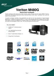
1 System tour
The <strong>Acer</strong> <strong>Altos</strong> <strong>G330</strong> Mk2 server is a single<br />
processor system featuring the latest in<br />
computing technology. It hosts a range of<br />
powerful and flexible features designed to<br />
meet the needs of various network<br />
environments. From simple networking<br />
functions to computing-intensive applications,<br />
the <strong>Altos</strong> <strong>G330</strong> Mk2 delivers.
3<br />
System specifications<br />
This section lists down the impressive computing features of the<br />
<strong>Altos</strong> <strong>G330</strong> Mk2 system.<br />
Performance<br />
Processor<br />
• Single Intel ® LGA775 processor socket supporting the following<br />
processor models:<br />
• Quad-Core Intel Xeon processor 3200 series<br />
• Dual-Core Intel Xeon processor 3000 series<br />
• Intel® Core2 Quad processor<br />
• Intel® Core2 Duo processor<br />
• Intel® Pentium® Dual-Core processor<br />
• Intel® Celeron® processor<br />
• 512 KB, 1 MB, 2 MB, 4 MB or 2x4 MB L2 cache<br />
• 1333, 1066, and 800 MHz front side bus (FSB) speed<br />
• Supports the following Intel technologies: 1<br />
• Intel Quad-Core Architecture<br />
• Intel Dual-Core Architecture<br />
• Intel Extended Memory 64 Technology (EM64T)<br />
• Intel Enhance Intel SpeedStep Technology (EIST)<br />
• Intel Virtualization Technology (VT)<br />
Chipset<br />
• North bridge - Intel 3200 Memory Controller Hub (MCH)<br />
• South bridge - Intel 82801IR I/O Controller Hub (ICH9R)<br />
1<br />
Support for dual core, quad core configuration, Hyper-Threading Technology<br />
and EM64T may vary depending on processor type specifications.
4<br />
1 System tour<br />
Memory<br />
• Four DIMM slots supporting DDR2 800 unbuffered ECC modules<br />
• Maximum memory capacity of 8 GB<br />
• Supports 512 MB, 1 GB, and 2 GB capacity modules<br />
• Supports dual-channel interleave operation 2<br />
PCI interface<br />
• Five PCI bus slots with four separate bus segments<br />
• One PCI Express x16 slot with x8 throughput (PCI-E 1 slot)<br />
• One PCI Express x8 slot with x4 throughput (PCI-E 2 slot)<br />
• One PCI Express x4 slot with x1 throughput (PCI-E 3 slot)<br />
• Two 32-bit/33 MHz/3.3V PCI slots (PCI 4 and PCI 5 slots)<br />
Video controller<br />
• Embedded XGI Z9s chipset<br />
• 16 MB DDR SDRAM<br />
SATA II controller<br />
• Integrated in the Intel ICH9R chipset<br />
• Data transfer rate of up to 3.0 Gb/s<br />
• Supports six onboard SATA ports<br />
• Onboard SATA RAID support<br />
• RAID 0,1 and 10 support<br />
Networking<br />
• One Gigabit Ethernet LAN port (RJ-45)<br />
• Broadcom BCM 5721 Gigabit Ethernet Controller<br />
Baseboard Management Controller (optional)<br />
• Baseboard Management Controller (BMC) module (optional)<br />
• Intelligent Platform Management Interface (IPMI) 2.0 compliant<br />
2<br />
Dual-channel memory mode requires that only memory modules of the same<br />
type, banking, stacking technology, and manufacturer be installed in the<br />
<strong>Altos</strong> <strong>G330</strong> Mk2 server.
5<br />
Media storage<br />
• Three 5.25-inch device bays<br />
• Optical disc drive (ODD) installed in the topmost bay<br />
(DVD-ROM or combo drive)<br />
• Two 5.25-inch bays support installation of optional DAT and<br />
AIT tape drives<br />
• One hard disk drive (HDD) cage bay supports the following<br />
options:<br />
• Hot-swap 3 or easy-swap HDD cages<br />
• Up to four SAS or SATA II drives<br />
• Media storage options<br />
I/O ports<br />
• One 3.5-inch floppy disk drive (FDD) bay for optional FDD<br />
installation<br />
• Two front USB 2.0 ports<br />
• PS/2 keyboard port<br />
• PS/2 mouse port<br />
• Serial port<br />
• Monitor port<br />
• Two rear USB 2.0 ports<br />
• One Gigabit LAN port<br />
(RJ-45)<br />
Power supply and ventilation<br />
• 350-watts ATX 12V PFC power supply with auto switching function<br />
• Support for the following cooling components:<br />
• One rear system fan<br />
• One processor heat sink-fan (HSF) assembly<br />
• Optional HDD fan for systems using at least two hard drives<br />
are installed in adjacent HDD bays.<br />
3<br />
The hot-swap HDD configuration is only available when the optional hot-plug<br />
backplane board is installed in the HDD cage.
6<br />
1 System tour<br />
Hardware monitoring and server management<br />
• Hardware monitoring for voltage, temperature, and fan speed<br />
detection integrated in the ITE 8718 chip<br />
• Status LED indicators for constant monitoring of basic system<br />
operations<br />
• <strong>Acer</strong> <strong>Server</strong> Management (ASM) monitors potential problem spots<br />
in the network environment<br />
• Trusted Platform Module (TPM) 1.2 support<br />
Operating system<br />
• Microsoft Windows <strong>Server</strong> 2003 x64 Edition<br />
• Microsoft Windows <strong>Server</strong> 2003<br />
• Red Hat ® Enterprise Linux ® 5.0 EM64T<br />
• Red Hat ® Enterprise Linux ® 5.0<br />
• SUSE Linux ® Enterprise <strong>Server</strong> 10.0 EM64T<br />
• SUSE Linux ® Enterprise <strong>Server</strong> 10.0<br />
Mechanical<br />
• Chassis<br />
• Tool-less chassis design for easy hardware access<br />
• Tower orientation<br />
• Dimensions<br />
– Height: 424.6 mm (16.72 in)<br />
– Depth: 479.7 mm (18.89 in)<br />
– Width: 185.9 mm (7.32 in)<br />
• Mainboard<br />
• Dimensions (length x width): 304.8 x 243.8 mm (12 x 9.6 in)<br />
• Form factor: Advanced Technology Extended (ATX)
7<br />
External and internal structure<br />
Front panel<br />
Mk2<br />
No. Component No. Component<br />
1 ODD mechanical eject hole 9 HDD activity indicator<br />
2 ODD activity indicator 10 Status/fault indicator<br />
3 Optical disc drive 11 HDD bay bezel<br />
4 ODD eject button 12 Security keylock<br />
5 5.25-inch drive bays 13 FDD eject button<br />
6 USB 2.0 ports 14 FDD activity indicator<br />
7 Power button 15 Floppy disk drive (optional)<br />
8 Power indicator<br />
Note: If you intend to install an optional floppy disk drive, refer to the<br />
documentation that came with the new drive for instructions.
8<br />
1 System tour<br />
Rear panel<br />
No. Icon Component<br />
1 Side panel release latch<br />
2 Expansion slot covers<br />
3 Gigabit LAN port<br />
4 Monitor port<br />
5 Serial port<br />
6 USB 2.0 ports<br />
7 PS/2 keyboard port<br />
8 PS/2 mouse port<br />
9 Power cable socket
9<br />
Internal components<br />
No.<br />
Component<br />
1 Release sliders for the 5.25-inch device bays<br />
2 Release slider for the FDD bay<br />
3 HDD cage<br />
4 HDD fan<br />
5 Hot-plug HDD backplane board<br />
6 Mainboard<br />
7 Processor heat sink-fan<br />
8 System fan<br />
9 Power supply unit<br />
Notes:<br />
• The HDD fan is an optional item. Use of it is only required when the<br />
system is using at least two hard drives are installed in adjacent HDD bays.<br />
• The hot-plug backplane board is an optional item.<br />
• Contact your local <strong>Acer</strong> representive for information on how to purchase<br />
these hardware options.
10<br />
1 System tour<br />
System boards<br />
Mainboard<br />
36<br />
37<br />
35<br />
34<br />
33<br />
32<br />
31<br />
30<br />
16 17<br />
18 19<br />
20 21<br />
29<br />
28 27<br />
26<br />
25<br />
24<br />
23<br />
22
11<br />
No. Component No. Component<br />
1 TOP: PS/2 Mouse Port<br />
Bottom: PS/2 Keyboard Port<br />
20 SATA port 4<br />
2 USB2.0 Port 21 SATA port 5<br />
3 Serial Port 22 TPM module connector<br />
4 Monitor Port 23 Front panel LED connector<br />
5 Gigabit LAN port 24 Serial port connector (COM 2)<br />
6 Processor socket 25 USB connector 1<br />
7 Processor HSF connector 26 USB connector 2<br />
8 DIMM A1 27 Chassis intrusion connector<br />
9 DIMM A2 28 IPMB_1 connector<br />
10 DIMM B1 29 IPMB_2 connector<br />
11 DIMM B2 30 BMC Module slot<br />
12 FDD connector 31 PCI 5 slot (32-bit/33 MHz/3.3 V)<br />
13 2x12 ATX power connector 32 PCI 4 slot (32-bit/33 MHz/3.3 V)<br />
14 HDD fan connector 33 PCI-E 3 slot PCI Express x4<br />
(with x1 throughput)<br />
15 I2C connector 34 PCI-E 2 slot PCI Express x8<br />
(with x4 throughput)<br />
16 SATA port 0 35 PCI-E 1 slot PCI Express x16<br />
(with x8 throughput)<br />
17 SATA port 1 36 Rear system fan connector<br />
18 SATA port 2 37 2x4 ATX power connector<br />
19 SATA port 3
12<br />
1 System tour<br />
Backplane board<br />
The backplane board attached to the rear of the hot-plug HDD cage is<br />
what differentiate it from the easy-swap HDD cage model.<br />
5<br />
No.<br />
Component<br />
1 HDD access LED control jumpers<br />
Close 2-3 – HDD LED control via pin 11 (default)<br />
2 HDD power cable connectors<br />
3 HDD data cable connector (SFF-8484)<br />
4 SAS Backplane Management cable connector<br />
5 HDD connectors
13<br />
BMC module<br />
The optional BMC module is the meeting point between the server<br />
hardware and the system management software. In conjunction with<br />
the mainboard hardware monitor, it allows system administrators to<br />
manage the system remotely over a network.<br />
No. Code Description<br />
1 SODIMM_1 BMC module mainboard connector<br />
2 U3 SDRAM (Synchronous Dynamic Random Access Memory)<br />
3 U1 H85/216x BMC chipset<br />
Note: <strong>Altos</strong> <strong>G330</strong> Mk2 does not support ARMC/3.
14<br />
1 System tour<br />
System jumpers<br />
No. Jumper Setting<br />
1 Clear CMOS 1-2 – Normal operation setting<br />
2-3 – The CMOS RAM contents will be cleared<br />
on the next reset.<br />
2 BIOS recovery 1-2 – Normal operation setting<br />
2-3 – BIOS recovery setting<br />
Note: The default setting for normal operation is 1-2 for all<br />
system jumpers.
15<br />
System LED indicators<br />
This section discusses the different status LED indicators located on the:<br />
• Front panel<br />
• Hot-plug HDD carrier<br />
• LAN port<br />
Knowing what each LED indicator signifies can aid in problem<br />
diagnosis and troubleshooting.<br />
Front panel LED indicators<br />
The LED indicators (green) mounted on the front panel allow the<br />
constant monitoring of the system’s power status and drive activity.<br />
Mk2<br />
No. Indicator Status Description<br />
1 ODD activity Blinking There is an ongoing ODD activity.
16<br />
1 System tour<br />
No. Indicator Status Description<br />
2 Power On The system is powered on.<br />
Blinking<br />
The system is in ACPI sleep mode.<br />
3 HDD activity Blinking There is an ongoing HDD activity.<br />
4 Status/fault 1 Solid green System is in normal mode.<br />
Solid<br />
amber<br />
Critical system threshold breach<br />
Access the Setup utility and view<br />
the system event log for details.<br />
5 FDD activity Blinking There is an ongoing FDD activity.<br />
1 The status/fault LED indicator is only enabled when the optional BMC module is installed<br />
on the mainboard. To purchase this option, contact your local <strong>Acer</strong> representative.<br />
Hot-plug HDD LED indicators<br />
A drive activity LED indicator is mounted on the hot-plug HDD carrier.<br />
The table below lists the possible drive states.<br />
Status Green Amber Description<br />
HDD access Blinking — Ongoing hot-plug HDD activity<br />
HDD failure — On Hot-plug HDD failure<br />
HDD rebuild Flashing green/amber HDD is rebuilding data.
17<br />
LAN port LED indicators<br />
The Gigabit LAN port located on the rear panel has two LED indicators<br />
that show its status.<br />
No. Indicator Status Description<br />
1 Network<br />
speed<br />
2 Network<br />
connection<br />
Solid yellow<br />
Solid green<br />
Off<br />
Solid green<br />
Blinking green<br />
Off<br />
GbE link network access<br />
100 Mbps link network access<br />
10 Mbps link network access<br />
Active network link<br />
Ongoing network data activity<br />
Off-line network
18<br />
1 System tour
2 System setup
This chapter gives you instructions on how to<br />
prepare the system for operation. Procedures for<br />
connecting peripherals are also explained.
21<br />
Setting up the system<br />
Pre-installation requirements<br />
Selecting a site<br />
Before unpacking and installing the system, select a suitable site for<br />
the system for maximum efficiency. Consider the following factors<br />
when choosing a site for the system:<br />
• Near a grounded power outlet<br />
• Clean and dust-free<br />
• Stable surface free from vibration<br />
• Well-ventilated and away from sources of heat<br />
• Secluded from electromagnetic fields produced by electrical<br />
devices such as air conditioners, radio and TV transmitters, etc.<br />
Checking the package contents<br />
Check the following items from the package:<br />
• <strong>Acer</strong> <strong>Altos</strong> <strong>G330</strong> Mk2 system<br />
• <strong>Acer</strong> <strong>Altos</strong> <strong>G330</strong> Mk2 System DVD<br />
• <strong>Acer</strong> <strong>Altos</strong> <strong>G330</strong> Mk2 accessory box<br />
• System keys (attached to the security keylock)<br />
If any of the above items are damaged or missing, contact your dealer<br />
immediately.<br />
Save the boxes and packing materials for future use.
22<br />
2 System setup<br />
Connecting peripherals<br />
The color-coded I/O ports on the rear panel support a variety of<br />
compatible peripherals.<br />
Note: Consult the operating system manual for information on<br />
how to configure the network setup.<br />
Caution: Do not route the power cord where it will be walked on<br />
or pinched by items placed against it. The server is designed to be<br />
electrically grounded (earthed). To ensure proper operation, plug<br />
the power cord into a properly grounded AC outlet only.
23<br />
Turning on the system<br />
After making sure that you have properly set up the system, applied<br />
power, and connected all the necessary peripherals, you can now<br />
power on the system.<br />
To turn on the system, press the power button on the front panel.<br />
The system starts up and displays a welcome message on the monitor.<br />
After that, a series of power-on self-test (POST) messages appears. The<br />
POST messages indicate if the system is running well or not.<br />
Note: If the system does not turn on or boot after pressing the<br />
power button, go to the next section for the possible causes of the<br />
boot failure.<br />
Aside from the POST messages, you can determine if the system is in<br />
good condition by checking if the following occurred.<br />
• The power status indicator on the front panel lights up green.<br />
• The Num Lock, Caps Lock, and Scroll Lock indicators on the<br />
keyboard light up.
24<br />
2 System setup<br />
Power-on problems<br />
If the system fails to boot after you have applied power, check the<br />
following factors that might have caused the boot failure.<br />
• The external power cord may be loosely connected.<br />
Check the power cord connection from the power outlet to the<br />
power cord socket on the rear panel. Make sure that the cord is<br />
properly connected to the power outlet and to the power cord<br />
socket.<br />
• No power comes from the grounded power outlet.<br />
Have an electrician check your power outlet.<br />
• Loose or improperly connected internal power cables.<br />
Check the internal cable connections. If you are not confident to<br />
perform this step, ask a qualified technician to assist you.<br />
Warning! Make sure all power cords are disconnected from<br />
the electrical outlet before performing this task.<br />
Note: If you have gone through the preceding actions and the<br />
system still fails to boot, ask your dealer or a qualified technician<br />
for assistance.
25<br />
Turning off the system<br />
There are two ways to turn off the server—via software or via<br />
hardware. The software procedure below applies to a system running<br />
on a Windows OS. For other OS shutdown procedures, refer to the<br />
related user documentation.<br />
To turn off the system via software:<br />
1 Press Ctrl+Alt+Delete on the attached keyboard or click Start on<br />
the Windows taskbar.<br />
2 Select Shut Down.<br />
3 Select Shut down from the drop-down menu, then click OK.<br />
To turn off the system via hardware:<br />
If you cannot shut down the server via software, press the power<br />
button for at least four seconds. Quickly pressing the button may put<br />
the server in a Suspend mode only.
26<br />
2 System setup
3 System upgrade
This chapter discusses the precautionary<br />
measures and installation procedures you<br />
need to know when upgrading the system.
29<br />
Installation precautions<br />
Before you install any server component, it is recommended that you<br />
read the following sections first. These sections contain important ESD<br />
precautions along with pre-installation and post-installation<br />
procedures.<br />
ESD precautions<br />
Electrostatic discharge (ESD) can damage static-sensitive hardware<br />
components, such as the processor, disk drives, and the system boards.<br />
Always observe the following precautions before you install a server<br />
component:<br />
• Do not remove a component from its protective packaging until<br />
you are ready to install it.<br />
• Do not touch the component pins, leads, or circuitry.<br />
• Components with a Printed Circuit Board (PCB) assembly should<br />
always be laid with the assembly-side down.<br />
• Wear a wrist grounding strap and attach it to a metal part of the<br />
server before handling components. If a wrist strap is not<br />
available, maintain contact with the server throughout any<br />
procedure requiring ESD protection.<br />
• Avoid moving around unnecessarily to minimize your body’s ESD.<br />
• Keep the work area free of nonconductive materials, such as<br />
ordinary plastic assembly aids and foam packing.
30<br />
3 System upgrade<br />
Pre-installation instructions<br />
Perform the steps below before you open the server or before you<br />
remove or replace any component.<br />
Warning! Failure to properly turn off the server before you<br />
start perform any hardware configuration may cause<br />
serious damage and bodily harm. Do not attempt the<br />
procedures described in the following sections unless you<br />
are a qualified service technician.<br />
1 Back up all important system and data files before performing any<br />
hardware configuration.<br />
2 Turn off the server and all connected peripherals.<br />
3 Unplug all power cables from their outlets.<br />
4 Disconnect all telecommunication cables from their ports.<br />
5 Place the server on a flat, stable surface.<br />
6 Open the server according to the instructions on page 31.<br />
7 Follow the ESD precautions described in the previous section when<br />
handling a server component.<br />
Post-installation instructions<br />
Perform the steps below after installing a server component.<br />
1 See to it that all components are installed according to the<br />
described step-by-step instructions.<br />
2 Reinstall any expansion board(s), peripheral(s), bracket(s) and<br />
system cable(s) that have previously been removed.<br />
3 Reinstall the side panel and the front bezels.<br />
4 Reconnect the power, peripheral, and telecommunication cables.<br />
5 Turn on the system.
31<br />
Opening the server<br />
Caution: Before you proceed, make sure that you have turned<br />
off the system and all peripherals connected to it. Read the<br />
"Pre-installation instructions" section page 30.<br />
You need to open the server before you can install upgrade<br />
components. The front bezels and (left) side panel are removable to<br />
allow access to the server’s internal components. Refer to the<br />
following sections for instructions.<br />
Removing the side panel<br />
1 Perform the pre-installation instructions described on page 30.<br />
2 Open the HDD bay bezel.<br />
(1) If necessary, insert the key into the lock and turn it<br />
counterclockwise until it points to the unlock icon.<br />
(2) Open the lower bezel to a 90° angle.<br />
3 Remove the side panel.<br />
(1) Loosen the two screws located on the rear edge of the<br />
side panel.<br />
(2) Move the side panel release latch all the way down to<br />
unfasten the panel from the chassis.
32<br />
3 System upgrade<br />
(3) Slide the side panel toward the rear of the chassis to detach it.<br />
Removing the front bezels<br />
1 Remove the side panel.<br />
2 Remove the front bezels.<br />
There are two front bezels protecting the 5.25-inch drive bays and<br />
the HDD bay. Remove the top bezel first.<br />
(1) Release the top bezel retention tabs from the chassis interior.<br />
(2) Pull the top bezel away from the chassis.<br />
(3) Pull the lower bezel upward to release its retention tabs from<br />
the chassis.<br />
(4) Pull the lower bezel away from the chassis.
Configuring a 5-25 inch storage device<br />
The three 5.25-inch device bays support a variety of storage devices for<br />
additional storage capacity and scalability. Go to page 5 for a list of<br />
supported storage devices.<br />
By default, the system ships with a DVD-ROM drive installed on the<br />
topmost device bay. You can choose to replace this default drive, or<br />
you can install a new storage device.<br />
To install an optional storage device:<br />
1 Perform the pre-installation instructions described on page 30.<br />
2 If you intend to replace the DVD drive, go to the next step.<br />
If you intend to install a new storage device, go to step 4.<br />
3 Remove the default DVD drive.<br />
(1) Disconnect the power and IDE cables from rear of the default<br />
DVD drive.<br />
(2) Move and hold the DVD drive release slider to the unlock<br />
position .<br />
(3) Pull the drive out of the device bay.<br />
33<br />
Proceed to step 5 for instructions on how to install a new<br />
storage device.
34<br />
3 System upgrade<br />
4 Use a flat-blade screwdriver to pry the dummy bezel off the device<br />
bay where you intend to install the new storage device.<br />
Keep this dummy bezel for future reinstallation.<br />
5 Install the new 5.25-inch storage device.<br />
(1) Move and hold the DVD drive release slider of the unlock<br />
position .<br />
(2) Slide the new 5.25-inch drive into the drive bay.<br />
(3) Move the release slider into the lock position .<br />
(4) Connect the power and data cables of the new storage device.<br />
6 Observe the post-installation instructions described on page 30.
35<br />
Configuring a hard drive<br />
The <strong>Altos</strong> <strong>G330</strong> Mk2 HDD cage bay accommodates both hot-plug and<br />
easy-swap HDD cage models. The main difference between these two<br />
cage models is the presence of a backplane board on the rear side of<br />
the hot-plug HDD cage. Both cage models support up to four SATA II or<br />
SAS hard disk drives. Users have the option to purchase extra hard disks<br />
to provide the system with additional storage capacity and scalability.<br />
Hard drive configuration reminders<br />
• A dummy HDD carrier occupies a vacant HDD bay. Users need to<br />
purchase a blank HDD carrier to install additional hard drive(s).<br />
• If you intend to install a SAS hard drive model, install the SAS or<br />
SAS RAID card option first.<br />
• If you intend to install at least two hard drives in adjacent HDD<br />
bays, an HDD fan is required to maintain proper system cooling.<br />
Contact your local <strong>Acer</strong> representative for more information on how to<br />
purchase these optional items.<br />
To remove a hot-plug hard drive:<br />
1 If necessary, unlock the front bezel, then pull it open.<br />
2 Remove the hot-plug hard drive from its bay.<br />
(1) Press the hard disk carrier button to release the ejector lever.<br />
(2) Use the ejector lever to pull the drive out of the cage.<br />
Make sure to support the drive when pulling it out of the<br />
cage.
36<br />
3 System upgrade<br />
To remove an easy-swap hard drive:<br />
1 Remove the side panel from the chassis.<br />
Go to page 31 for instructions.<br />
2 Disconnect the data and power cables from their HDD connectors.<br />
The figure below shows the cable connections for a SAS HDD<br />
connected to an optional SAS/SAS RAID expansion card. Easy-swap<br />
HDD configuration also supports SATA HDDs connected to the<br />
onboard SATA connectors.<br />
3 Press the hard disk carrier button to release the ejector lever.<br />
4 Use the ejector lever to pull the drive out of the cage.<br />
Make sure to support the drive when pulling it out of the cage.<br />
5 Observe the post-installation instructions described on page 30.
37<br />
To install a hot-plug hard drive:<br />
1 If necessary, unlock the HDD bay bezel, then pull it open.<br />
2 Pull out the dummy HDD carrier from the cage.<br />
3 Prepare the new blank HDD carrier for installation.<br />
(1) Remove the four screws that secures the blank frame.<br />
You will use these screws to secure the hard disk later.<br />
(2) Detach the plastic frame from the HDD carrier.
38<br />
3 System upgrade<br />
4 Align the new hard disk with the HDD carrier, then secure it with<br />
the four screws you removed in step 3-1.<br />
5 Install the new hard drive into the cage.<br />
(1) Slide the drive into the cage with the ejector lever still<br />
extended.<br />
(2) Make sure that the drive is properly inserted before pushing<br />
the lever back until it clicks into place.<br />
To install an easy-swap hard drive:<br />
1 Remove the side panel from the chassis.<br />
Go to page 31 for instructions.<br />
2 Observe steps 2 through 5 of the previous section.<br />
3 Connect the data and power cables to their HDD connectors.<br />
4 Observe the post-installation instructions described on page 30.
39<br />
Upgrading the processor<br />
<strong>Altos</strong> <strong>G330</strong> Mk2 has one LGA775 processor socket that supports a<br />
variety of Intel processor models. Refer to page 3 to for a list of these<br />
supported processor options.<br />
This section explains the procedures for removing and installing the<br />
processor and heat sink-fan.<br />
Processor configuration precautions<br />
• Handle the processor and the HSF assembly carefully. Damage to<br />
either may prevent the system from functioning properly.<br />
• Do not touch the pins on either the processor or the processor<br />
socket; they are very sensitive and are easily damaged.<br />
• Do not force the processor into the socket. When properly<br />
aligned, the processor will easily fit into place.<br />
• Be sure that the server has the most recent ROM version. Failure<br />
to flash the ROM before installing a new processor can cause<br />
system failure.<br />
To upgrade the processor:<br />
1 Perform the pre-installation instructions described on page 30.<br />
2 Lay the server on its side (components showing).<br />
3 If necessary, remove any accessory boards or cables that prevent<br />
access to the HSF.
40<br />
3 System upgrade<br />
4 Remove the HSF from the chassis.<br />
The figure below shows the HSF type available for the <strong>Altos</strong> <strong>G330</strong><br />
Mk2 system.<br />
(1) Disconnect the processor HSF cable from its mainboard<br />
connector.<br />
(2) Loosen the four HSF mounting pins.<br />
(3) Twist the HSF sightly to break the thermal grease bond loose.<br />
Once the thermal grease bond is broken, lift the HSF away<br />
from the mainboard.<br />
(4) Lay down the HSF in an upright position—with the thermal<br />
patch facing upward. Do not let the thermal patch touch the<br />
work surface.<br />
5 Use an alcohol pad to wipe off the thermal grease from both the<br />
HSF assembly and the processor socket retention plate.
41<br />
6 Remove the default processor.<br />
Warning! The processor becomes very hot when the<br />
system is on. Allow it to cool off first before handling.<br />
(1) Press down on the socket lever while pulling it towards the<br />
center of the mainboard to disengage it from the socket hook.<br />
(2) Fully open the load lever.<br />
(3) Press the rear tab with your finger tip to bring the front end<br />
of the retention plate up slightly.<br />
(4) Open the plate to expose the socket body.<br />
(5) Grasp the processor by its edges and lift it out of its socket.<br />
7 Store the old processor inside an anti-static bag.<br />
8 Remove the new processor from its box, handling it by the edges.<br />
9 Remove the protective shipping cover from the new processor.
42<br />
3 System upgrade<br />
10 Install the new processor.<br />
(1) Hold the processor by its edges, then insert it in the socket.<br />
Make sure that the alignment tabs on the socket fit the two<br />
notches located on the edge of the processor. The pins are<br />
keyed in such a way that you cannot install the processor in<br />
the wrong orientation without bending the pins.<br />
(2) Close the retention plate.<br />
(3) Press down on the socket lever while pushing it towards the<br />
center of the processor socket to engage it under the socket<br />
hook.<br />
11 Apply a thin layer of an <strong>Acer</strong>-approved thermal interface material<br />
to the processor base and the bottom side of the HSF.<br />
Make sure that only a very thin layer is applied so that both<br />
contact surfaces are still visible.
43<br />
12 Reinstall the HSF assembly.<br />
The figure below shows the HSF type available for the <strong>Altos</strong> <strong>G330</strong><br />
Mk2 system.<br />
(1) Align then insert the HSF on top of the retention plate.<br />
(2) Tighten the four mounting pins a few threads in, observing a<br />
diagonally opposite pattern, then tighten them completely to<br />
secure the heat sink to the processor base.<br />
(3) Reconnect the HSF cable to its mainboard connector.<br />
13 Observe the post-installation instructions described on page 30.
44<br />
3 System upgrade<br />
Upgrading the system memory<br />
This section explains the procedures for removing and installing a<br />
memory module.<br />
<strong>Altos</strong> <strong>G330</strong> Mk2 has four DDR2-800 DIMM slots. Each slot supports<br />
512 MB, 1 GB or 2 GB memory modules. The maximum memory<br />
capacity is 8 GB.<br />
System memory interface<br />
<strong>Altos</strong> <strong>G330</strong> Mk2 has four DIMM slots divided into two memory<br />
channels.<br />
• Channel A - DIMM A1 and DIMM A2<br />
• Channel B - DIMM B1 and DIMM B2<br />
System memory configuration guidelines<br />
• To ensure data integrity, use only <strong>Acer</strong>-approved DDR2 800<br />
unbuffered ECC modules in 512 MB, 1 GB, or 2 GB capacities.<br />
• Use identical modules—same type, banking, stacking technology,<br />
and manufacturer.<br />
• The minimum memory configuration is one DIMM, installed in the<br />
DIMM A1 slot (the slot closest to the processor socket).<br />
• The system does not support a three-DIMM memory configuration.
45<br />
• DIMMs on channel A (DIMM A1 and A2) are paired with DIMMs on<br />
channel B (DIMM B1 and B2) to enable two-way interleaving.<br />
When only two DIMMs are being used, the population order must<br />
be DIMM A1 and DIMM B1 to ensure dual-channel operating<br />
mode.<br />
• For best performance and dual-channel interleave operation,<br />
DIMM modules must be installed or removed in matched pairs,<br />
following the slot sequence: DIMM A1 and B1 first, then DIMM A2<br />
and B2.<br />
• Observe the population sequence illustrated in the table below<br />
when installing a memory module.<br />
Memory channel DIMM slot Population order<br />
A DIMM A1 1<br />
A DIMM A2 3<br />
B DIMM B1 2<br />
B DIMM B2 4<br />
• The table below lists the supported memory installation based on<br />
the memory interleave configuration.<br />
Interleave<br />
mode<br />
Channel A<br />
Channel B<br />
DIMM A1 DIMM A2 DIMM B1 DIMM B2<br />
Total<br />
memory<br />
Single<br />
channel<br />
512 MB 512 MB<br />
1 GB 1 GB<br />
2 GB 2 GB
46<br />
3 System upgrade<br />
Interleave<br />
mode<br />
Channel A<br />
Channel B<br />
DIMM A1 DIMM A2 DIMM B1 DIMM B2<br />
Total<br />
memory<br />
512 MB 512 MB 1 GB<br />
1 GB 1 GB 2 GB<br />
Dual<br />
channel<br />
2 GB 2 GB 4 GB<br />
512 MB 512 MB 512 MB 512 MB 2 GB<br />
1 GB 1 GB 1 GB 1 GB 4 GB<br />
2 GB 2 GB 2 GB 2 GB 8 GB<br />
To remove a memory module:<br />
1 Perform the pre-installation instructions described on page 30.<br />
2 Lay the server on its side (components showing).<br />
3 If necessary, remove any cables that prevent access to the DIMM<br />
slots.<br />
4 Locate the memory module you intend to remove.<br />
5 Remove the memory module.<br />
(1) Press the retaining clips on both sides of the slot outward to<br />
release the DIMM.<br />
(2) Hold the DIMM by its edges, then gently pull it upward to<br />
remove it.<br />
6 Store the removed memory module inside an anti-static bag.<br />
7 If you intend to install a new memory module, proceed to the next<br />
section for related procedure, otherwise observe the<br />
post-installation instructions described on page 30.
47<br />
To install memory module:<br />
1 Perform steps 1 through 3 of the previous section.<br />
2 Select an empty DIMM slot.<br />
3 If necessary, open the holding clips of the selected DIMM slot.<br />
4 Remove the new memory module from its protective packaging,<br />
handling it by the edges.<br />
5 Install the new memory module.<br />
(1) Align the module so that the notch on the slot fits the keyed<br />
edge of the module, then press the module at both ends until<br />
the retaining clips snap into place.<br />
If you insert a module but it does not fit easily into the slot,<br />
you have inserted it incorrectly. Reverse the orientation of the<br />
module and insert it again.<br />
(2) Make sure to firmly press the retaining clips inward to lock the<br />
module in place.<br />
If the holding clips do not close, the module is not properly<br />
inserted.<br />
6 Observe the post-installation instructions described on page 30.<br />
The system automatically detects the amount of memory installed.<br />
Run the BIOS setup utility to view the new value for total system<br />
memory.
48<br />
3 System upgrade<br />
Installing an expansion card<br />
This section explains how to install an expansion card.<br />
<strong>Altos</strong> <strong>G330</strong> Mk2 has five PCI bus slots, namely:<br />
• One PCI Express x16 slot with x8 throughput (PCI-E 1 slot)<br />
• One PCI Express x8 slot with x4 throughput (PCI-E 2 slot)<br />
• One PCI Express x4 slot with x1 throughput (PCI-E 3 slot)<br />
• Two 32-bit/33 MHz/3.3V PCI bus slots (PCI 4, PCI5 slots)<br />
1 slot<br />
3 slot<br />
2 slot<br />
4<br />
5<br />
To install an expansion card:<br />
1 Perform the pre-installation instructions described on page 30.<br />
2 If necessary, remove any cables that prevent access to the<br />
expansion slots.<br />
3 Locate an empty expansion slot that is compatible with the<br />
specification of the card you intend to install.<br />
4 Install the expansion card.<br />
(1) Pull the card bracket latch slightly upward.<br />
(2) Detach the card bracket latch from the chassis.<br />
(3) Pull out the slot cover opposite the selected expansion slot.<br />
Store it for future reassembly.
49<br />
Caution: Do not discard the slot cover. If the expansion card is<br />
removed in the future, the slot cover must be reinstalled to<br />
maintain proper system cooling.<br />
5 Remove the expansion card from its protective packaging,<br />
handling it by the edges.<br />
6 Install the new expansion card.<br />
(1) Insert the card into the selected slot.<br />
Make sure that the card is properly seated.<br />
(2) Insert the lower end of the card bracket latch to its chassis<br />
notch.<br />
(3) Secure the card bracket latch tab to the chassis.
50<br />
3 System upgrade<br />
7 Connect the necessary cables to the expansion card as required.<br />
8 Observe the post-installation instructions described on page 30.<br />
When you turn on the system, the BIOS setup automatically<br />
detects and assigns resources to the new device (applicable only to<br />
Plug-and-Play expansion cards).
51<br />
Installing the BMC module<br />
The optional BMC module allows system administrators to manage the<br />
<strong>Altos</strong> <strong>G330</strong> Mk2 system remotely over a network.<br />
To install the BMC module:<br />
1 Perform the pre-installation instructions described on page 30.<br />
2 Locate the IPMI_1 slot. If necessary, remove any boards or cables<br />
that prevent access to it.<br />
3 If necessary, open the holding clips of the IPMI_1 slot.<br />
4 Remove the BMC module from its protective packaging, handling<br />
it by the edges.<br />
5 Install the BMC module.<br />
(1) Align the module so that the notch on the IPMI_1 slot fits the<br />
keyed edge of the module, then press the module at both<br />
ends to seat it fully into the slot.<br />
When the module is properly installed, the holding clips will<br />
automatically lock in place.<br />
(2) Secure the module with the one screw.<br />
6 Observe the post-installation instructions described on page 30.
52<br />
3 System upgrade<br />
Installing the TPM module<br />
The optional TPM module allows system administrators to enhance the<br />
security of <strong>Altos</strong> <strong>G330</strong> Mk2 system.<br />
To install the TPM module:<br />
1 Perform the pre-installation instructions described on page 30.<br />
2 Locate the TPM module connector. If necessary, remove any boards<br />
or cables that prevent access to it.<br />
3 Remove the TPM module from its protective packaging, handling<br />
it by the edges.<br />
4 Install the TPM module.<br />
(1) Insert the TPM module into the TPM module connector.<br />
5 Observe the post-installation instructions described on page 30.
4 System BIOS
This chapter gives information about the<br />
system BIOS and discusses how to configure<br />
the system by changing the settings of the<br />
BIOS parameters.
55<br />
BIOS overview<br />
BIOS setup is a hardware configuration program built into the system's<br />
Basic Input/Output System (BIOS). Since most systems are already<br />
properly configured and optimized, there is no need to run this utility.<br />
You will need to run this utility under the following conditions.<br />
• When changing the system configuration settings<br />
• When redefining the communication ports to prevent any conflicts<br />
• When modifying the power management configuration<br />
• When changing the password or making other changes to the<br />
security setup<br />
• When a configuration error is detected by the system and you are<br />
prompted ("Run Setup" message) to make changes to the BIOS<br />
setup<br />
Note: If you repeatedly receive Run Setup messages, the battery<br />
may be bad. In this case, the system cannot retain configuration<br />
values in CMOS. Ask a qualified technician for assistance.<br />
BIOS setup loads the configuration values in a battery-backed<br />
nonvolatile memory called CMOS RAM. This memory area is not part<br />
of the system RAM which allows configuration data to be retained<br />
when power is turned off.<br />
Before you run the PhoenixBIOS Setup Utility, make sure that you have<br />
saved all open files. The system reboots immediately after you close<br />
the Setup.<br />
Note: PhoenixBIOS Setup Utility will be simply referred to as<br />
"Setup" or "Setup utility" in this guide.<br />
The screenshots used in this guide display default system values.<br />
These values may not be the same those found in your system.
56<br />
4 System BIOS<br />
Entering BIOS setup<br />
1 Turn on the server and the monitor.<br />
If the server is already turned on, close all open applications, then<br />
restart the server.<br />
2 During POST, press F2.<br />
If you fail to press F2 before POST is completed, you will need to<br />
restart the server.<br />
The Setup Main menu will be displayed showing the Setup’s menu<br />
bar. Use the left and right arrow keys to move between selections<br />
on the menu bar.<br />
BIOS setup primary menus<br />
The tabs on the Setup menu bar correspond to the six primary BIOS<br />
Setup menus, namely:<br />
• Main<br />
• Advanced<br />
• Security<br />
• <strong>Server</strong><br />
• Boot<br />
• Exit<br />
In the descriptive table following each of the menu screenshots,<br />
settings in boldface are the default and suggested settings.
57<br />
BIOS setup navigation keys<br />
Use the following keys to move around the Setup utility.<br />
• Left and Right arrow keys – Move between selections on the<br />
menu bar.<br />
• Up and Down arrow keys – Move the cursor to the field you<br />
want.<br />
• PgUp and PgDn keys – Move the cursor to the previous and next<br />
page of a multiple page menu.<br />
• Home – Move the cursor to the first page of a multiple page<br />
menu.<br />
• End – Move the cursor to the last page of a multiple page menu.<br />
• + and - keys – Select a value for the currently selected field (only if<br />
it is user-configurable). Press these keys repeatedly to display each<br />
possible entry, or the Enter key to choose from a pop-up menu.<br />
Note: Grayed-out fields are not user-configurable.<br />
• Enter key – Display a submenu screen.<br />
Note: Availability of submenu screen is indicated by a (>).<br />
• Esc – If you press this key:<br />
• On one of the primary menu screens, the Exit menu displays.<br />
• On a submenu screen, the previous screen displays.<br />
• When you are making selections from a pop-up menu, closes<br />
the pop-up without making a selection.<br />
• F1 – Display the BIOS setup General Help panel.<br />
• F9 – Press to load default system values.<br />
• F10 – Save changes made the Setup and close the utility.
58<br />
4 System BIOS<br />
Main menu<br />
Parameter<br />
System Time<br />
System Date<br />
BIOS Version<br />
BIOS Date<br />
Processor<br />
CPU Type<br />
CPU Speed<br />
CPU Count<br />
Total Memory<br />
Size<br />
Description<br />
Set the system time following the hour-minute-second<br />
format.<br />
Set the date following the weekday-month-day-year<br />
format.<br />
Version number of the BIOS setup utility<br />
Date when the BIOS setup utility was created<br />
Technical specifications for the installed processor<br />
Total size of system memory detected during POST
59<br />
Advanced menu<br />
The Advanced menu display submenu options for configuring the<br />
function of various hardware components. Select a submenu item,<br />
then press Enter to access the related submenu screen.
60<br />
4 System BIOS<br />
Advanced Processor Options<br />
Parameter Description Option<br />
CPU Type<br />
CPU Speed<br />
FSB Speed<br />
Processor CPUID<br />
Processor L2<br />
Cache<br />
Processor model name<br />
The processor speed is the speed at which a<br />
microprocessor executes instructions. Clock<br />
speeds are expressed in megahertz (MHz),<br />
with 1 MHz being equal to 1 million cycles<br />
per second. The faster the clock, the more<br />
instructions the CPU can execute per<br />
second.<br />
Front side bus frequency<br />
Processor ID number<br />
Processor second-level cache size detected during POST<br />
Note: This field is not shown on the above screenshot.<br />
C1 Enhanced<br />
Mode<br />
Select whether to enable the C1 Enhanced<br />
mode for the processor. If enabled, all<br />
logical processors in a physical processor<br />
will run in a C1 state.<br />
Enabled<br />
Disabled
61<br />
Parameter Description Option<br />
Intel<br />
Virtualization<br />
Technology<br />
Execute Disable<br />
Bit<br />
Intel EIST<br />
Support<br />
Processor<br />
Multicore<br />
Trusted<br />
Execution<br />
Technology<br />
Hardware<br />
Prefetcher<br />
Adjacent Cache<br />
Line Prefetch<br />
Select whether to enable the Intel<br />
Virtualization Technology function. VT<br />
allows a single platform to run multiple<br />
operating systems in independent<br />
partitions.<br />
Select whether to enable the Intel Execute<br />
Disable Bit (XD) function. The XD function<br />
allows the processor to divide the system<br />
memory into areas for storage of processor<br />
instructions or for storage of data. When a<br />
malicious worm attempts to insert code in<br />
the buffer, the processor disables code<br />
execution, preventing damage or worm<br />
propagation.<br />
Enable/Disable Enhanced Intel SpeedStep<br />
Technology.<br />
Enable/Disable processor multicore<br />
Enable/Disable Trusted Execution<br />
Technology<br />
Select whether to enable the speculative<br />
prefetch unit of the processor.<br />
When enabled, cache lines are fetched in<br />
pairs. When disabled, only the required<br />
cache line is fetched.<br />
Enabled<br />
Disabled<br />
Enabled<br />
Disabled<br />
Enabled<br />
Disabled<br />
Enabled<br />
Disabled<br />
Enabled<br />
Disabled<br />
Enabled<br />
Disabled<br />
Enabled<br />
Disabled
62<br />
4 System BIOS<br />
Memory Configuration<br />
Parameter Description Option<br />
System Memory<br />
Extended<br />
Memory<br />
DIMM Group A1,<br />
A2, B1, B2 Status<br />
Total size of system memory detected during POST<br />
Total size of extended memory detected during POST<br />
The size of memory installed on each of the FBD slots.<br />
Memory Retest<br />
Select whether to delete the historical<br />
memory data log. System memory will<br />
be retested on the next boot-up.<br />
Yes<br />
No
63<br />
Advanced Chipset Control<br />
Parameter Description Option<br />
Wake On LAN/<br />
PME<br />
Wake On Ring<br />
Wake On RTC<br />
Alarm<br />
Select whether to wake up the system<br />
when a LAN or PME event is detected.<br />
Select whether to wake up the system<br />
when an incoming call is detected on<br />
the modem.<br />
Select whether to wake up the system<br />
when an RTC alarm is detected.<br />
Enabled<br />
Disabled<br />
Enabled<br />
Disabled<br />
Enabled<br />
Disabled
64<br />
4 System BIOS<br />
PCI Configuration<br />
Parameter Description Option<br />
PCI Slot 1 - 5<br />
Option ROM<br />
Onboard LAN<br />
Control<br />
LAN Option<br />
ROM Scan<br />
Onboard VGA<br />
Control<br />
When enabled, this setting will initialize<br />
the device expansion ROM for the related<br />
PCI slot.<br />
Enable or Disable the onboard LAN Device<br />
by setting item to the desired value<br />
Select whether to enable the selected<br />
onboard LAN device. When enabled,<br />
device expansion ROM will be initialized.<br />
Enable or Disable the onboard VGA by<br />
setting item to the desired value<br />
Enabled<br />
Disabled<br />
Enabled<br />
Disabled<br />
Enabled<br />
Disabled<br />
Enabled<br />
Disabled
65<br />
I/O Device Configuration<br />
Parameter Description Option<br />
Serial Port A/B<br />
Base I/O address<br />
PS/2 Mouse<br />
USB Controller<br />
When enabled allows you to configure<br />
the serial port settings.<br />
When set to Auto allows the server’s<br />
BIOS or OS to select a configuration.<br />
When set to Disabled, displays no<br />
configuration for the serial port.<br />
Base I/O address and IRQ setting for the<br />
selected serial port<br />
Enable this parameter if you intend to<br />
use a mouse or trackball with a PS/2<br />
interface.<br />
Enables or disables the onboard USB<br />
controller.<br />
Enabled<br />
Disabled<br />
Auto<br />
3F8/IRQ4<br />
2F8/IRQ3<br />
3E8/IRQ4<br />
2E8/IRQ3<br />
Enabled<br />
Disabled<br />
Enabled<br />
Disabled
66<br />
4 System BIOS<br />
Parameter Description Option<br />
Legacy USB<br />
Support<br />
Enables or disables support for legacy<br />
USB devices.<br />
Enabled<br />
Disabled<br />
IDE Configuration<br />
The IDE Configuration submenu lets you define the parameter settings<br />
related to the system hard drive(s).<br />
Parameter Description Option<br />
Serial ATA<br />
Native Mode<br />
Operation<br />
SATA RAID<br />
Enable<br />
SATA AHCI<br />
Enable<br />
Select whether to enable support for<br />
SATA devices.<br />
Select the native mode for the SATA<br />
function.<br />
Enable/Disable SATA RAID function.<br />
Set this item to enable SATA AHCI<br />
function for WinXP-SP1+IAA driver<br />
supports AHCI mode.<br />
Enabled<br />
Disabled<br />
Auto<br />
Serial ATA<br />
Enabled<br />
Disabled<br />
Enabled<br />
Disabled
67<br />
I/O Channel 0/Secondary Master/Slave<br />
Parameter Description Option<br />
Type Selects the drive type. Auto<br />
None<br />
CD-ROM<br />
ATAPI Removable<br />
IDE Removable<br />
User<br />
Total Sectors<br />
Maximum<br />
Capacity<br />
Total number of sectors available in the selected hard drive.<br />
Maximum capacity of the selected hard drive.<br />
Multi-Sector<br />
Transfers<br />
LBA Mode<br />
Control<br />
Set the multi-Sector transfer mode.<br />
Selects the hard disk drive translation<br />
method. For drivers with more than<br />
504 MB, LBA mode is necessary.<br />
16 Sectors<br />
Disabled<br />
2 Sectors<br />
4 Sectors<br />
8 Sectors<br />
Enabled<br />
Disabled
68<br />
4 System BIOS<br />
Parameter Description Option<br />
32-bit I/O<br />
Transfer<br />
Mode<br />
Ultra DMA<br />
Mode<br />
Enables or disables the 32-bit data<br />
transfer function<br />
Select a transfer mode to enhance hard<br />
disk performance.<br />
Selects DMA (Direct Memory Access)<br />
mode.<br />
Disabled<br />
Enabled<br />
Fast PIO 4<br />
Standard<br />
Fast PIO 1<br />
Fast PIO 2<br />
Fast PIO 3<br />
FPIO 3/DMA 1<br />
FPIO 4/DMA 2<br />
Mode 6<br />
Disabled<br />
Mode 0<br />
Mode 1<br />
Mode 2<br />
Mode 3<br />
Mode 4<br />
Mode 5
69<br />
Floppy Configuration<br />
The Floppy Configuration submenu displays the type of floppy disk<br />
drive installed in the server.
70<br />
4 System BIOS<br />
Boot Configuration<br />
Parameter Description Option<br />
Boot-time<br />
Diagnostic<br />
Screen<br />
Multiprocessor<br />
Specification<br />
POST Error<br />
Pause<br />
After Power<br />
Failure<br />
Choose whether to display the boot-time<br />
diagnostic screen during POST.<br />
Select the multiprocessor (MP) specification<br />
revision level.<br />
Note: Some operating system will require a<br />
1.1 setting for compatibility reasons.<br />
Select whether to pause POST when a<br />
boot-up error is detected.<br />
Defines the power state to resume to after a<br />
system shutdown that is due to an<br />
interruption in AC power.<br />
When set to Last State, the system will<br />
return to the active power state prior to<br />
shutdown.<br />
When set to Stay Off, the system remains<br />
off after power shutdown.<br />
When set to Power On, the system will be<br />
turned on from a power failure.<br />
Disabled<br />
Enabled<br />
1.4<br />
1.1<br />
Enabled<br />
Disabled<br />
Last State<br />
Stay Off<br />
Power On
71<br />
Parameter Description Option<br />
NumLock<br />
Security Mode<br />
for PWR/RST<br />
button<br />
Select the NumLock behavior during<br />
boot-up.<br />
Enable/Disable Security mode for PWR<br />
button and RST button<br />
On<br />
Off<br />
Enabled<br />
Disabled
72<br />
4 System BIOS<br />
Security menu<br />
The Security menu allows you to safeguard and protect the system<br />
from unauthorized use by setting up access passwords.<br />
There are three types of passwords that you can set:<br />
• Supervisor password<br />
Entering this password will allow the user to access and change all<br />
settings in the Setup Utility.<br />
• User password<br />
Entering this password will restrict a user’s access to the Setup<br />
menus. To enable or disable this field, a supervisor password must<br />
first be set. A user can only access and modify the System Time,<br />
System Date, and Set User Password fields.<br />
• Power-on password<br />
When the Password on Boot field is enabled, a password will be<br />
required to boot up the server. To enable or disable this field, a<br />
supervisor password must first be set.
73<br />
Parameter Description Option<br />
Supervisor<br />
Password Is<br />
This parameter indicates whether a<br />
supervisor password has been assigned.<br />
Clear<br />
Enabled<br />
User Password Is<br />
This parameter indicates whether a user<br />
password has been assigned.<br />
Clear<br />
Enabled<br />
Set Supervisor<br />
Password<br />
Set User<br />
Password<br />
Press Enter to configure the supervisor password.<br />
Press Enter to configure the user password.<br />
Password On<br />
Boot<br />
TPM Support<br />
Select Enabled to activate security check<br />
during POST.<br />
Enable/Disable Trusted Platform Module<br />
support<br />
Disabled<br />
Enabled<br />
Disabled<br />
Enabled<br />
Setting a system password<br />
1 Use the up/down keys to select a password parameter (Set<br />
Supervisor Password or Set User Password), then press Enter.<br />
A password box will appear.<br />
2 Type a password then press Enter.<br />
The password may consist of up to six alphanumeric characters<br />
(A-Z, a-z, 0-9).<br />
3 Retype the password to verify the first entry then press Enter<br />
again.<br />
4 Press F10.<br />
5 Select Yes to save the new password and close the Setup Utility.
74<br />
4 System BIOS<br />
Changing a system password<br />
1 Use the up/down keys to select a password parameter (Set<br />
Supervisor Password or Set User Password), then press Enter.<br />
2 Type the original password then press Enter.<br />
3 Type a new password then press Enter.<br />
4 Retype the password to verify the first entry then press Enter<br />
again.<br />
5 Press F10.<br />
6 Select Yes to save the modified password and close the Setup<br />
Utility.<br />
Removing a system password<br />
1 Use the up/down keys to select a password parameter (Set<br />
Supervisor Password or Set User Password), then press Enter.<br />
2 Enter the current password then press Enter.<br />
3 Press Enter twice without entering anything in the new and<br />
confirm password fields.<br />
After doing this, the system automatically sets the related<br />
password parameter to Clear.
75<br />
<strong>Server</strong> menu<br />
Parameter<br />
System Management<br />
Console Redirection<br />
Event Log Configuration<br />
Description<br />
Displays basic system ID information, as well as<br />
BIOS and BMC firmware versions.<br />
Press Enter to access the related submenu.<br />
Displays console redirection-related settings.<br />
Press Enter to access the related submenu.<br />
Displays DMI event log-related settings.<br />
Press Enter to access the related submenu.
76<br />
4 System BIOS<br />
System Management<br />
The System Management submenu is a simple display page for basic<br />
system ID information, as well as BIOS and BMC firmware versions.<br />
Items on this window are non-configurable.<br />
Parameter<br />
Clear Case Open Status<br />
Description<br />
Press Enter to select whether to clear case open<br />
status
77<br />
Console Redirection<br />
Parameter Description Option<br />
COM Port<br />
Address<br />
Baud Rate<br />
Select whether to enable console<br />
redirection.<br />
Console redirection enables users to<br />
manage the system from a remote<br />
location.<br />
Select the baud rate for console<br />
redirection.<br />
Onboard COM A<br />
Onboard COM B<br />
Disabled<br />
300<br />
1200<br />
2400<br />
9600<br />
19.2K<br />
38.4K<br />
57.6K<br />
115.2K
78<br />
4 System BIOS<br />
Parameter Description Option<br />
Console<br />
Type<br />
Flow<br />
Control<br />
Continue<br />
C.R. After<br />
POST<br />
Select a terminal type to be used for<br />
console redirection.<br />
Assign control for the console redirection<br />
flow.<br />
Select whether to enable console<br />
redirection after POST.<br />
VT100,<br />
VT100 8bit<br />
PC-ANSI 7bit<br />
VT100+<br />
VT-UTF8<br />
None<br />
XON/OFF<br />
CTS/RTS<br />
On<br />
Off
79<br />
Event Log Configuration<br />
Parameter Description Option<br />
Clear All Event<br />
Logs<br />
Press Enter then select whether to clear all entries in<br />
the system event log.<br />
Log POST Sys.<br />
Event<br />
Select whether to enable the BIOS event<br />
log to be integrated in the system event<br />
log.<br />
Disabled<br />
Enabled
80<br />
4 System BIOS<br />
Boot menu<br />
The Boot menu allows you to set the drive priority during system<br />
boot-up. BIOS setup will display an error message if the drive(s)<br />
specified is not bootable.<br />
By default, the server searches for boot devices in the following order:<br />
1 Floppy disk drive<br />
2 Optical disc drive<br />
3 Hard drive
81<br />
Exit menu<br />
The Exit menu displays the various options to quit from the BIOS setup.<br />
Highlight any of the exit options then press Enter.<br />
Parameter<br />
Exit Saving<br />
Changes<br />
Exit Discarding<br />
Changes<br />
Load Setup<br />
Defaults<br />
Discard<br />
Changes<br />
Save Changes<br />
Description<br />
Saves changes made and close the BIOS setup.<br />
Discards changes made and close the BIOS setup.<br />
Loads the default settings for all BIOS setup parameters.<br />
Setup Defaults are quite demanding in terms of<br />
resources consumption. If you are using low-speed<br />
memory chips or other kinds of low-performance<br />
components and you choose to load these settings, the<br />
system might not function properly.<br />
Discards all changes made in the BIOS setup.<br />
Saves changes made in the BIOS setup.
82<br />
4 System BIOS
5 System<br />
troubleshooting
This chapter provides possible solutions for specific<br />
problems. If you cannot correct the problem,<br />
contact your local <strong>Acer</strong> representative or<br />
authorized dealer for assistance.
85<br />
Pre-troubleshooting procedure<br />
If you encounter any problem, ensure first that the system has the<br />
latest BIOS version. In addition to the BIOS, also update any drivers<br />
used for components that you have installed in the system, such as<br />
video drivers, network drivers, and storage drivers.<br />
Resetting the system<br />
Before going through in-depth troubleshooting, attempt first to reset<br />
the system using one of the methods below.<br />
Perform Purpose To do this<br />
Soft boot<br />
reset<br />
Cold boot<br />
reset<br />
To clear the system memory and reload<br />
the operating system.<br />
To clear the system memory, restart<br />
POST, and reload the operating system.<br />
This will halt power to all peripherals.<br />
Press Ctrl+Alt+Del<br />
Press the system<br />
power button off<br />
and then on.
86<br />
5 System troubleshooting<br />
Initial system startup problems<br />
Problems that occur at initial system startup are usually caused by an<br />
incorrect installation or configuration. Hardware failure is a less<br />
possible cause. If the problem you are experiencing is with a specific<br />
application, see the "There is problem with the software program"<br />
item on page 92.
87<br />
Initial troubleshooting checklist<br />
Use the checklist below to eliminate the possible cause for the problem<br />
you’re encountering.<br />
• AC power is available at the wall outlet<br />
• Is the power supply module properly installed<br />
• Is the system power cord properly plugged into the power supply<br />
module socket and connected to a NEMA 5-15R outlet for<br />
100-120 V or a NEMA 6-15R outlet for 200-240 V<br />
• Are all peripheral cables correctly connected and secured<br />
• Did you press the power button to turn the server on (power<br />
indicator should be lit green)<br />
• Are all device drivers properly installed<br />
• Is the hard disk drive properly formatted and configured<br />
• Are the BIOS configuration settings correct<br />
• Is the operating system properly loaded<br />
Refer to the operating system documentation.<br />
• Are all hardware components compliant with the tested<br />
components lists<br />
• Are all internal cables correctly connected and secured<br />
• Is the processor fully seated in its mainboard socket<br />
• Are all standoffs in the proper location and not touching any<br />
components, causing a potential short<br />
• Are all add-in expansion cards fully seated in their slots<br />
• Are all system jumpers correctly set<br />
• Are all switch settings on add-in boards and peripheral devices<br />
correct<br />
To check these settings, refer to the manufacturer’s<br />
documentation that comes with them. If applicable, ensure that<br />
there are no conflicts (e.g., two add-in boards sharing the same<br />
interrupt).
88<br />
5 System troubleshooting<br />
Hardware diagnostic testing<br />
This section provides a detailed approach to identifying a hardware<br />
problem and its cause.<br />
Checking the boot-up status<br />
Caution: Before disconnecting any peripheral cables from the<br />
server, turn off the system and any peripheral devices. Failure to<br />
do so can cause permanent damage to the system and/or the<br />
peripheral device.<br />
1 Turn off the system and all external peripheral devices.<br />
2 Disconnect all peripheral devices from the system, except for the<br />
keyboard and the monitor.<br />
3 Make sure the system power cord is plugged into a properly<br />
grounded AC outlet and in the power cable socket.<br />
4 Make sure both the monitor and the keyboard are correctly<br />
connected to the system.<br />
5 Turn on the monitor.<br />
6 Set the display brightness and contrast controls to at least two<br />
thirds of their maximum range.<br />
Refer the documentation that came with your monitor.<br />
7 If the operating system normally loads from the hard drive, make<br />
sure there is no diskette in the FDD and no disc in the ODD.<br />
8 If the power indicator is lit, attempt to boot from a floppy diskette<br />
or from a disc.<br />
9 Turn on the system.<br />
If the power indicator did not light up, see the "Power indicator<br />
does not light" item on page 90.
89<br />
Verifying the condition of the storage devices<br />
As POST determines the system configuration, it tests for the presence<br />
of each storage device installed in the system. As each device is<br />
checked, its activity indicator should turn on green briefly. Check the<br />
activity indicators for the hard drive(s), DVD-ROM drive, floppy drive,<br />
and any other 5.25-inch device you may have installed.<br />
If any of these indicators fail to light up, refer to the related problems<br />
listed in the "Component troubleshooting" section.<br />
Confirming loading of the operating system<br />
Once the system boots up, the operating system prompt appears on<br />
the screen. The prompt varies according to the operating system. If<br />
the operating system prompt does not appear, see the "No characters<br />
appear the display monitor" item on page 93.
90<br />
5 System troubleshooting<br />
Component troubleshooting<br />
Listed below are specific problems that may arise during the use of<br />
your server and their possible solutions.<br />
Power indicator does not light.<br />
Do the following:<br />
• Make sure the power supply module is properly installed.<br />
• Make sure the power cord is connected correctly.<br />
• Make sure that the wall outlet has power. Test it by plugging<br />
another device.<br />
• Make sure the power indicator on the front panel is lit up green.<br />
• Remove all add-in cards and see if the system boots up.<br />
If reboot is successful, install the cards back in one at a time with a<br />
reboot between each addition to determine if one of them is<br />
causing the problem.<br />
• Make sure that you have correctly installed system compliant<br />
memory modules, and that the system DIMM population<br />
guidelines were observed.<br />
• Make sure that you have installed a system compliant processor.<br />
FDD activity indicator does not light.<br />
Do the following:<br />
• Make sure the FDD data and power cables are properly connected.<br />
• Check that relevant switches and jumpers for the FDD are set<br />
correctly.<br />
• Check that the FDD is properly configured.
91<br />
HDD activity indicator does not light.<br />
Do the following:<br />
• Make sure the HDD data and power cables are connected correctly.<br />
• Check that relevant switches and jumpers on the hard drive and on<br />
the backplane board (for hot-plugs HDD) are set correctly.<br />
DVD drive activity indicator does not light.<br />
Do the following:<br />
• Make sure the IDE and power cables are properly connected.<br />
• Check that relevant switches and jumpers on the drive are set<br />
correctly.<br />
• Check that the drive is properly configured.<br />
DVD tray cannot be ejected.<br />
Insert the tip of a paperclip into the small hole on the DVD drive.<br />
Slowly pull the tray out from the drive until the tray is fully extended.<br />
DVD drive cannot read a disc.<br />
Do the following:<br />
• Make sure you are using the correct type of disc.<br />
• Make sure the disc is properly seated in the drive.<br />
• Make sure the disc is free from scratches or any contaminant.<br />
• Make sure the drive’s IDE and power cables are properly<br />
connected.<br />
Newly installed memory modules are not detected.<br />
Do the following:<br />
• Make sure the memory modules specifications comply with the<br />
system requirements.<br />
• Make sure the memory modules have been populated according<br />
to the system guidelines.<br />
• Make sure the memory modules are properly installed in their<br />
slots.
92<br />
5 System troubleshooting<br />
Network connection indicators do not light.<br />
Do the following:<br />
• Check the cabling and network equipment to make sure that they<br />
are in proper condition.<br />
• Reinstall the network drivers.<br />
• Try another port or hub on the switch.<br />
Network activity indicators do not light.<br />
Do the following:<br />
• Make sure the correct network drivers are loaded on the system.<br />
• Network might be idle.<br />
Peripheral device connected to a USB port does not work.<br />
Do the following:<br />
• Reduce the number of external devices connected to a USB hub.<br />
• Refer to the documentation that came with the device.<br />
There is problem with the software program.<br />
Do the following:<br />
• Verify that the software is properly configured for the system.<br />
Refer to the software installation and operation documentation<br />
for instructions on setting up and using the software.<br />
• Try a different version of the software to see if the problem is with<br />
the copy you are using. If the other version runs correctly on the<br />
system, contact your vendor about the defective software.
93<br />
No characters appear on the monitor.<br />
Check the following:<br />
• Is the keyboard functioning Test it by turning the Num Lock<br />
function on and off to check if the Num Lock indicator lights up.<br />
• Is the monitor plugged in and turned on If you are using a switch<br />
box, is it switched to the correct system<br />
• Are the brightness and contrast controls on the monitor properly<br />
adjusted<br />
• Is the monitor signal cable properly connected<br />
• Does this monitor work correctly if plugged into a different<br />
system<br />
• Remove all add-in cards and see if the system boots up.<br />
If reboot is successful, install the cards back in one at a time with a<br />
reboot between each addition to determine if one of them is<br />
causing the problem.<br />
• Make sure that you have correctly installed system compliant<br />
memory modules, and that the system DIMM population<br />
guidelines were observed.<br />
• Make sure that you have installed a system compliant processor.<br />
If you are using an add-in video controller card, do the following:<br />
1 Verify that the monitor works using the onboard video controller.<br />
2 Verify that the add-in video controller card is fully seated in its slot.<br />
3 Reboot the system for the changes to take effect.<br />
4 If there are still no characters on the screen after you reboot the<br />
system, reboot it again.<br />
Take note of the beep codes emitted during POST. This<br />
information may be required if you seek technical assistance.<br />
If POST does not emit any beep code and characters still does not<br />
appear, the monitor or the video controller may be defective.<br />
Contact your local <strong>Acer</strong> representative or authorized dealer for<br />
technical assistance.
94<br />
5 System troubleshooting
Appendix A: <strong>Server</strong><br />
management tools
This appendix gives an overview of the<br />
different server management tools<br />
supported by your server.
97<br />
<strong>Server</strong> management overview<br />
The server management tools supported by the <strong>Altos</strong> <strong>G330</strong> Mk2 system<br />
is listed in the table below.<br />
Tool<br />
PhoenixBIOS Setup<br />
Utility<br />
ASM (<strong>Acer</strong> <strong>Server</strong><br />
Management)<br />
Onboard SATA RAID<br />
Configuration Utility<br />
LSI MegaRAID SAS RAID<br />
Configuration Utility<br />
Function<br />
Use this tool to configure the different hardware<br />
components and system functions (memory,<br />
processor, and security settings). Go to the BIOS<br />
setup chapter on page 55 for details.<br />
This utility allows a system administrator to<br />
remotely manage the server in a network<br />
environment through a single management<br />
station. For detailed instructions on how to install<br />
and use this utility, refer to the user<br />
documentation accompanying it.<br />
Use any of these utilities to configure RAID for<br />
the system hard drives. The LSI utilitiy is only<br />
available when the corresponding SAS controller<br />
board option is installed in the server. Proceed to<br />
the next section for instructions on how to use<br />
these utilities.
98<br />
Appendix A: <strong>Server</strong> management tools<br />
RAID configuration utilities<br />
RAID option for the <strong>Altos</strong> <strong>G330</strong> Mk2 system is provided through either<br />
the onboard SATA controller or through a controller board option (LSI<br />
MegaRAID SAS RAID controller).<br />
Caution: Creating a RAID volume erases all data previously saved<br />
in the hard drives. Make sure that you back up important files<br />
before starting a RAID configuration process.<br />
Onboard SATA RAID Configuration Utility<br />
This section explains how to create a RAID 1 volume using the onboard<br />
SATA controller.<br />
To enable the onboard SATA RAID controller:<br />
1 Turn on the server and the monitor.<br />
If the server is already turned on, close all open applications, then<br />
restart the server.<br />
2 During POST, press F2 to access the BIOS Setup Utility.<br />
3 Select the Advanced | IDE Configuration submenu.<br />
4 Change the setting of the SATA RAID Enable field from Disabled to<br />
Enabled.<br />
5 Press F10.<br />
6 Select Yes to save the new SATA RAID settings and close the Setup<br />
Utility.
99<br />
Entering the onboard SATA RAID Configuration Utility<br />
During POST, press Ctrl-M in the LSI MegaRAID Software RAID<br />
information screen.<br />
Loading the onboard LSI SATA RAID default setting<br />
1 In the onboard LSI RAID Configuration Utility, select Objects from<br />
the Management menu.<br />
2 Select Adapter from the Objects list.<br />
The available adapter options will be displayed.<br />
3 Press Enter in the adapter list.<br />
The adapter settings will be displayed.<br />
4 Select Factory Default, then YES to load the default settings.<br />
5 Close the configuration utility.<br />
6 Press Ctrl+Alt+Del to reboot the system.<br />
Creating the RAID 1 volume<br />
1 In the onboard LSI RAID Configuration Utility, select<br />
Configuration from the Management menu.<br />
2 Select New Configuration from the Configuration menu, then<br />
select YES to continue.<br />
An array selection window displays the devices connected to the<br />
current controller.<br />
3 Press the arrow keys to choose the specific physical drives, then<br />
press the space bar to associate the selected drive with the current<br />
array.<br />
The indicator for the selected drive change from READY to<br />
ONLINE.<br />
4 Add two more drives to the current array, then press Enter.<br />
5 Press Enter again to select another array to configure.<br />
6 Press the space bar to select the array, then press F10 to configure<br />
the logical drive.<br />
7 Accept the default RAID level (RAID1), then press Enter to return<br />
to the array selection window.<br />
8 Press Enter to end the array configuration.
100<br />
Appendix A: <strong>Server</strong> management tools<br />
9 Select YES to save the configuration, then press any key to return<br />
to the Configuration menu.<br />
Initializing the RAID volume<br />
1 Press Esc to return to the Management menu.<br />
2 Select Initialize from the Management menu.<br />
All logical drives should be listed under Logical Drives.<br />
3 Press the space bar to select the drives for initialization.<br />
The selected drive will be shown in yellow.<br />
4 Press F10, then select YES to start the initialization process.<br />
5 Once initialization is complete, press any key to continue.<br />
6 Press Esc to return to the Management menu.<br />
7 Press Esc, then select YES to close the configuration utility.<br />
Press Ctrl+Alt+Del to reboot the system, then proceed to the OS<br />
installation.<br />
Assigning a Hot Spare Disk<br />
1 Select Objects from Management menu.<br />
2 Select Physical Drive from Objects. All of the HDDs will be listed.<br />
3 Select a drive marked as READY and press Enter.<br />
4 Select Make Hot Spare and press Enter.<br />
5 Select Yes then you will see the HDD is changed from READY to<br />
HOTSP.<br />
6 Press ESC to return to the Management Menu.<br />
Save and Exit LSI RAID Configuration Utility<br />
1 When RAID configuration, initialization and assigning hot spare is<br />
completed, press ESC in the Management Menu and select YES to<br />
exit the RAID Configuration Utility.<br />
2 Press Ctrl + Alt + Del to reboot the server.<br />
3 Now you can start to install OS.
LSI MegaRAID SAS 8708ELP RAID Configuration<br />
Utility<br />
This section briefly shows how to create RAID with LSI MegaRAID SAS<br />
8708ELP.<br />
To initialize the LSI MegaRAID SAS RAID Configuration Utility:<br />
101<br />
1 Turn on the server and the monitor.<br />
If the server is already turned on, close all open applications, then<br />
restart the server.<br />
2 During POST, press Ctrl-H on the RAID BIOS prompt.<br />
After POST completion, the Adapter Selection window will appear.<br />
3 Click Start to launch the Configuration menu.<br />
To load the factory default RAID setting:<br />
1 On the Configuration menu, select Adapter Properties to display<br />
the current adapter settings.<br />
2 Click Next to change the adapter setting.<br />
3 Change the setting of Set Factory Defaults from No to Yes, then<br />
click Submit.<br />
4 Press Ctrl+Alt+Del to reboot the server.<br />
To create and initialize a RAID volume:<br />
1 Access the Configuration menu.<br />
2 Click Configuration Wizard.<br />
3 Click Add Configuration, then click Next.<br />
4 Click Custom Configuration, then click Next.<br />
5 Use the Ctrl key to select the drives that you want to add into the<br />
array.<br />
6 After selecting the drives, click Accept DG, then Next.<br />
7 Select the RAID Level you want to use.<br />
8 Create the logical volume and specify its size on the Select Size<br />
field, then click Accept.<br />
9 After creating a logical volume on all of the RAID volume, click<br />
Accept, then Yes to save the configuration.
102<br />
Appendix A: <strong>Server</strong> management tools<br />
10 Click Yes to initialize the new logical drives.<br />
All the created logical drives will be listed.<br />
11 Click on Home to revert to the Configuration menu.<br />
12 Select Exit, then Yes.<br />
13 Press Ctrl+Alt+Del to reboot the system.<br />
Proceed to the installation of the operating system. Refer to the<br />
user documentation that came with your OS for related<br />
instructions.<br />
To assign a hot spare disk:<br />
1 Access the Configuration menu.<br />
2 Under Physical Drives, select a free disk marked as UNCONF<br />
GOOD.<br />
3 Select Make Global Dedicated HSP or Make Dedicated HSP,<br />
then click Go.<br />
4 Click on Home to revert to the Configuration menu.<br />
Under Physical Drives, the assigned hot spare disk is marked as<br />
Hotsapare and highlighted in pink.<br />
LSI MegaRAID SAS 8204ELP RAID Configuration<br />
Utility<br />
This section briefly shows how to create RAID with LSI MegaRAID SAS<br />
8204ELP.<br />
Starting LSI MegaRAID SAS RAID Configuration Utility<br />
During POST, press CTRL-M in the LSI MegaRAID information screen.<br />
Loading Factory default setting<br />
1 Select Objects from Management menu.<br />
2 Select Adapter from Objects. The selectable adapter will be<br />
listed.<br />
3 Press Enter on the adapter and the adapter setting will be shown<br />
on the screen. You can change the setting from this menu.<br />
4 Select Factory Default and Yes to load the default settings.
103<br />
5 Exit the configuration utility and press + + to<br />
reboot the server.<br />
Creating a RAID volume<br />
1 1.Select Configuration from Management Menu.<br />
2 Select New Configuration from the Configuration Menu. An<br />
array selection window displays the devices connected to the<br />
current controller.<br />
3 Press the arrow keys to choose specific physical drives and press<br />
spacebar to associate the selected drive with the current array. The<br />
indicator for selected drive change from READY to ONLINE.<br />
4 After you adding the drives to current array, press Enter to finish<br />
creating current array.<br />
5 Press Enter again to select array to configure.<br />
6 Press spacebar to select the array and press F10 to configure the<br />
logical drive<br />
7 Select Accept and press Enter to use the default setting for the<br />
RAID volume.<br />
8 Press Enter to end the array configuration.<br />
9 Select YES to Save Configuration and press any key to return to<br />
the Configuration Menu.<br />
10 Press ESC to return to the Management Menu.<br />
Initial RAID Volume<br />
1 Select Initialize from Management Menu. All logical drives<br />
should be listed under Logical Drives.<br />
2 Press Spacebar to select drives for initialization. The selected drive<br />
will be shown in yellow.<br />
3 After selecting the drives, press F10 and select YES to start the<br />
initialization process.<br />
4 When initialization is complete, press ESC to continue.<br />
5 Press ESC to return to the Management Menu.<br />
Assigning a Hot Spare Disk<br />
1 Select Objects from Management Menu.<br />
2 Select Physical Drive from Objects. All of the HDDs will be listed.
104<br />
Appendix A: <strong>Server</strong> management tools<br />
3 Select a drive marked as READY and press Enter.<br />
4 Select Make Hot Spare and press Enter.<br />
5 Select Yes then you will see the HDD is changed from READY to<br />
HOTSP.<br />
6 Press ESC to return to the Management Menu.<br />
Save and Exit LSI RAID Configuration Utility<br />
1 When RAID configuration, initialization and assigning hot spare is<br />
completed, press ESC in the Management Menu and select YES<br />
to exit the RAID Configuration Utility.<br />
2 Press Ctrl + Alt + Del to reboot the server.<br />
3 Now you can start to install OS.
Index<br />
Numerics<br />
5.25 inch device bays<br />
install 33<br />
location 7<br />
supported devices 5<br />
B<br />
Basic Input/Output System, see BIOS<br />
55<br />
BIOS<br />
clear CMOS jumper 14<br />
CMOS RAM 55<br />
configure 56<br />
overview 55<br />
recovery jumper 14<br />
BIOS Setup<br />
Advanced Chipset Control 63<br />
Advanced menu 59<br />
Advanced Processor Options 60<br />
Boot Configuration 70<br />
Boot menu 80<br />
Console Redirection 77<br />
enter Setup 56<br />
Event Log Configuration 79<br />
Exit menu 81<br />
Floppy Configuration 69<br />
I/O Device Configuration 65<br />
IDE Configuration 66<br />
Main menu 58<br />
Memory Configuration 62<br />
navigation keys 57<br />
PCI Configuration 64<br />
Security menu 72<br />
<strong>Server</strong> menu 75<br />
System Management 76<br />
BMC module<br />
board layout 13<br />
install 51, 52<br />
boot-time diagnostic screen 70<br />
boot-up sequence 80<br />
C<br />
CMOS battery<br />
location 11<br />
CMOS RAM 55<br />
console redirection 77<br />
D<br />
DVD-ROM drive<br />
remove 33<br />
troubleshooting 91<br />
105<br />
E<br />
easy-swap HDD<br />
cable connections 36<br />
install 38<br />
remove 36<br />
electrostatic discharge, see ESD precautions<br />
29<br />
expansion card<br />
I/O interface 48<br />
install 48<br />
F<br />
FDD, see floppy disk drive 7<br />
floppy disk drive<br />
activity indicator 16<br />
location 7<br />
mainboard connector 11<br />
replace 7<br />
troubleshooting 90<br />
front bezels, remove 32<br />
front panel 7<br />
H<br />
hard disk drive<br />
activity indicator 16<br />
configuration guidelines 35<br />
easy-swap, install 38<br />
easy-swap, remove 36<br />
HDD fan option 9<br />
hot-plug, install 37<br />
hot-plug, remove 35<br />
troubleshooting 91<br />
hard drive<br />
BIOS settings 66<br />
RAID configuration 98<br />
hardware monitor<br />
specification 6<br />
HDD fan<br />
location 9<br />
mainboard connector 11<br />
HDD, see hard disk drive 5
106<br />
heat sink-fan<br />
install 43<br />
remove 40<br />
hot-plug HDD<br />
activity indicator 16<br />
backplane board 12<br />
install 37<br />
remove 35<br />
HSF, see heat sink-fan 5<br />
I<br />
I/O port connections 22<br />
Intel processor technologies<br />
XD function 61<br />
L<br />
LAN port<br />
location 8<br />
specifications 4<br />
troubleshooting 92<br />
LED indicators<br />
front panel 15<br />
HDD carrier 16<br />
LAN port 17<br />
LSI MegaRAID SAS RAID Configuration<br />
Utility 101<br />
M<br />
mechanical specifications<br />
chassis 6<br />
mainboard 6<br />
media storage<br />
controller 4<br />
specification 5<br />
upgrade option 5<br />
memory<br />
BIOS settings 62<br />
configuration guidelines 44<br />
install 47<br />
population order 45<br />
remove 46<br />
troubleshooting 91<br />
monitor port 8<br />
O<br />
ODD, see optical disc drive 7<br />
Onboard SATA RAID Configuration<br />
Utility 98<br />
operating system support 6<br />
optical disc drive<br />
activity indicator 15<br />
location 7<br />
replace 33<br />
P<br />
PCI bus slots 48<br />
BIOS settings 64<br />
PhoenixBIOS Setup Utility, see BIOS<br />
Setup 56<br />
POST<br />
error pause 70<br />
power<br />
boot-up problems 24<br />
boot-up sequence 80<br />
button, location 7<br />
cable socket 8<br />
power supply unit 9<br />
status indicator 16<br />
troubleshooting 90<br />
turn off 25<br />
turn on 23<br />
power off<br />
via hardware 25<br />
via software 25<br />
power-on password 72<br />
processor<br />
BIOS information 58<br />
BIOS settings 60<br />
remove 41<br />
socket location 11<br />
upgrade 39<br />
upgrade precautions 39<br />
PS/2 keyboard port 8<br />
PS/2 mouse port 8<br />
R<br />
RAID configuration<br />
LSI MegaRAID SAS RAID Configuration<br />
Utility 101,<br />
102<br />
Onboard SATA RAID Configuration<br />
Utility 98<br />
rear panel 8<br />
S<br />
security keylock 7<br />
serial port<br />
BIOS setting 65
107<br />
location 8<br />
server management<br />
specification 6<br />
tools 97<br />
side panel<br />
release latch 8<br />
remove 31<br />
specification<br />
chipset 3<br />
hardware monitoring 6<br />
I/O ports 5<br />
mechanical 6<br />
media storage 5<br />
memory 4<br />
networking 4<br />
operating system 6<br />
PCI interface 4<br />
power supply 5<br />
processor 3<br />
server management 6<br />
system cooling 5<br />
video controller 4<br />
supervisor password 72<br />
system boards<br />
backplane board 12<br />
BMC module 13<br />
system fan<br />
cable connector 11<br />
location 9<br />
system jumpers<br />
BIOS recovery 14<br />
clear CMOS 14<br />
system passwords<br />
change 74<br />
power-on password 72<br />
remove 74<br />
set 73<br />
supervisor password 72<br />
user password 72<br />
system reset<br />
cold boot 85<br />
soft boot 85<br />
system setup<br />
connect peripherals 22<br />
pre-installation requirements<br />
21<br />
turn on system 23<br />
system upgrade<br />
5.25 inch storage device 33<br />
BMC module 51, 52<br />
ESD precautions 29<br />
expansion card 48<br />
hard disk drive 35<br />
memory 44<br />
post-installation instructions 30<br />
pre-installation instructions 30<br />
processor 39<br />
T<br />
troubleshooting<br />
check firmware update 85<br />
display problems 93<br />
DVD-ROM drive problems 91<br />
FDD problem 90<br />
hardware diagnostics 88<br />
HDD problem 91<br />
initial checklist 87<br />
initial startup problems 86<br />
memory problem 91<br />
network problems 92<br />
power indicator problem 90<br />
software program problem 92<br />
system reset 85<br />
USB device problems 92<br />
U<br />
USB ports<br />
front 7<br />
rear 8<br />
troubleshooting 92<br />
user password 72<br />
W<br />
wake-up events<br />
Wake on LAN 63<br />
Wake on Ring 63<br />
Wake on RTC alarm 63