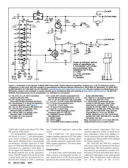
Figure 1—Schematic of the Simple 10-Meter QRP Transmitter. Unless otherwise specified, resistors are 1 /8-W, 5%-tolerance carboncompositionor film units. MO part numbers in parentheses are Mouser (Mouser Electronics, 958 N Main St, Mansfield, TX 76063-4827;tel 800-346-6873, 817-483-4422, fax 817-483-0931; sales@mouser.com; http://www.mouser.com; RS part numbers are RadioShack; the900-series numbers (not available in stores) identify parts available by Web-site ordering at http://www.radioshack.com; tel 800 THESHACK). Equivalent parts can be substituted; n.c. indicates no connection.C1, C6, C10—0.1 µF, 50 V monolithicceramic (RS 272-109)C2, C4—33 pF, 50 V ceramic(from RS 276-806 Picofarad 50-Pack)C3—Homemade 2- to 60-pF air-dielectricvariable capacitor; see Figure 2.C5—2.2 µF, 35 V tantalum (RS 900-2172)C7—270 pF, 300 V or greater, mica(Mouser 5982-15-500V270)C8—180 pF, 300 V or greater, mica(Mouser 5982-15-500V180)C9—0.0047 µF, 2 kV ceramic(RS 900-7214)C11—8 pF, 50 V ceramic (selected fromRS-276-806 Picofarad 50-Pack), or trytwo 4.7 pF, 50 V (RS 272-120) in parallelL1—2.4 µH, 1.5-A RF choke (RS 900-4834)L2—11 turns #18 enameled wire,1/4-inch ID, 1 /2-inch longL3—10 turns #18 enameled wire,1/4-inch ID, 9 /16-inch longQ1—TIP115 PNP Darlington powertransistor (MO 511-TIP115)Q2—VN88AFD power MOSFET(RS 900-5544)S1—DPDT toggleS2—SPST toggleU1—74AC240N octal 3-state invertingbuffer (RS 900-3626)U2—7805 5-V, 1-A positive regulator,TO-220 case (RS 276-1770)Y1—28,010-kHz fundamental-modecrystal in HC-6/U case, 20-pF loadcapacitance; (JAN Crystals, 2341Crystal Dr, PO Box 06017, Ft Myers, FL33906-6017; tel 800-JAN XTAL, 941-936-2397, fax 941-936-3750; InternationalCrystal Mfg Co, 10 N Lee, PO Box26330, Oklahoma City, OK 73126-0330;tel 800-725-1426, 405-236-3741, fax 800-322-9426). See text.Misc: Enclosure (2 1 /8×3×5 1 /4-inch [RS 270-238]),hardware and a crystal holder28,010-kHz crystal covers about 75% of theDX portion of the band. 3C3, the homebrew compression capacitorshown in Figure 2 and photographs,gives better resolution and tuning rangethan can be obtained from a conventionalair-dielectric variable capacitor. A bentpiece of 0.016-inch-thick brass becomes theequivalent of a capacitor’s rotor plate. 4 Abit of copper foil mounted on a section ofPC-board material acts as the capacitor’sstator. (The PC-board’s foil can be cut witha sharp knife and the unwanted foil removedafter heating it with a soldering44 <strong>March</strong> <strong>2000</strong>iron.) Connect the capacitor’s stator to thecrystal.Use a 0.0047-µF, 1-kV disk-ceramicoutput-coupling capacitor at C9. The ratherlarge antenna current may destroy physicallysmaller capacitors (especially monolithicceramic capacitors). Use mica capacitorsat C7 and C8.ConstructionA 2-inch wide, 0.016-inch-thick brassstrip is used as a ground plane for this circuit.Small pieces of PC-board materialepoxied to the ground plane act as solderlands for several components. This constructionapproach results in much lowerstray inductance, better heat sinking, reducedconstruction time and, perhaps, betterappearance than possible with standardPC-board construction. 5The 74AC240 and 7805 ICs, switchesand crystal socket are mounted on the brassground plane. The final amplifier and keyingtransistor are mounted on another 2×2-inch piece of 0.016-inch-thick brass that issoldered at right angles to the main groundplane. This configuration makes efficientuse of the space in the 2 1 / 8×3×
Here’s another view of C3, this time fromthe top.Figure 2—Mechanical assembly of C3; see text and accompanying photographs.On the rear panel of the 10-metertransmitter, four phono jacks provideconnection to the power supply (PWR),receiver (RCVR PWR and RCVR ANT) andthe station antenna (ANT). A 1 /4-inch KEYjack is beneath the phono connectors.The receiver/transmit (R/T) and SPOTtoggle switches are at the rear of the toppanel, with the crystal socket toward theenclosure’s front.5 1 /4-inch aluminum box (Radio Shack 270-238) used to house the transmitter.Holes drilled in the top surface of thealuminum box align with matching holesin the ground plane keeping the groundplanein contact with the aluminum box forefficient heat flow and good grounding. Thehomebrew capacitor is mounted on the frontlip of the box; the input and output connectorsare mounted on the box’s rear lip.U1, the 74AC240, is mounted “deadbug” style (ie, on its back with its legspointing up). This minimizes several verycritical lead lengths. The pin-10 groundlead and the leads of the bypass capacitorat pin 20 must be as short as possible. U1’sunused pins (3, 5 and 7) are folded ontothe IC’s belly; the grounded pins (1, 10, 13,15, 17 and 19) are bent downward and solderedto the ground plane. Pins 2, 4, 6, 8and 9 are strapped together, as are pins 12,14, 16 and 18.Satisfactory heat-sinking is obtained bybolting Q1, Q2 and U2 to the brassgroundplane. Because the tabs of Q1 andQ2 are not at ground potential, mica insulatorsand nylon shoulder washers(RadioShack 276-1373, TO-220 mountinghardware) are needed. Because the micainsulator forms part of the capacitance usedin the output filter, using a different heatsinkingtechnique will require output-circuitcomponent-value changes. 6 The 7805voltage regulator, U2, does not require amica insulator.Most of the components are wired pointto-point.Five 3 /8× 3 /8-inch pieces of PCboardmaterial epoxied to the groundplaneact as solder lands for the coils, one end ofR4, and the junction of R1, R2, C2, and C3.The coils are mounted at right angles toeach other to minimize coupling.Power SupplyAlthough this transmitter can be poweredby a standard 13.8-V supply, best performancerequires 24 V. The simple, wellfiltered(but unregulated) supply shown inFigure 3 is ideal. Physically separate thepower supply from the transmitter to preventpin 11 of U1 from picking up 60-Hzhum.Ready to go for 10-meter QRP!TroubleshootingThis transmitter is easy to troubleshoot.It draws roughly 60 mA key up and 200 to300 mA (depending on the supply voltage)with the key down. Check that the 7805output is +5 V and that the collector voltageof Q1 (the TIP115) rises to about 1 Vless than the supply when the key is closed.I measured 3.7 W of RF output with a 24-V<strong>March</strong> <strong>2000</strong> 45
- Page 6 and 7: March 2000 Volume 84 Number 3David
- Page 11 and 12: THE AMERICAN RADIORELAY LEAGUE INC
- Page 14: Get to Know Your Section ManagerThe
- Page 18: Senate CommerceChairman andPresiden
- Page 22 and 23: GEORGE DOMINICK, W4UWCLooking for a
- Page 26 and 27: CORRESPONDENCEYour opinions count!
- Page 30 and 31: By Stephen Stuntz, N0BFImagine ridi
- Page 32 and 33: By David A. Rosenthal, N6TSTDXing W
- Page 34 and 35: It was a ham’s dream, sitting onM
- Page 36 and 37: always start at the beginning of me
- Page 38 and 39: An insideview of theQRSerprototype.
- Page 40 and 41: Kits and BoardsWhile the original T
- Page 42 and 43: TT2 PerformanceKeying quality with
- Page 44 and 45: Figure 1—Schematic of the meter-m
- Page 48 and 49: tacts I had while using this transm
- Page 50 and 51: chandisers are free to develop “s
- Page 52 and 53: WORKBENCHPROJECTS AND INFORMATION F
- Page 54 and 55: THE HELP DESKSchematic Symbols52 Ma
- Page 56 and 57: paddle. This can be done with eithe
- Page 58 and 59: creator) was providing free PSK31 s
- Page 60 and 61: By H. Ward Silver, N0AXTest Your Kn
- Page 62 and 63: HINTS & KINKSA SIMPLE ANTENNA FLIPP
- Page 64 and 65: By Dave Patton, NT1N2000 Annual Mee
- Page 66 and 67: The Board welcomed three new Vice D
- Page 68 and 69: Craigie nominated Mr. Butler. Mr. B
- Page 70 and 71: D.C., with the specific responsibil
- Page 72 and 73: Table 1Elecraft K2, serial number 0
- Page 74 and 75: two inductors. Don’t let this hap
- Page 76 and 77: Like most transceivers these days,
- Page 78 and 79: Table 2Alinco DJ-V5TH, serial numbe
- Page 80 and 81: FCC NewsENHANCED AMATEUR ENFORCEMEN
- Page 82 and 83: tem is not legal to use as it’s c
- Page 84 and 85: chance to do it. It may be several
- Page 86 and 87: officials and the hundreds of train
- Page 88 and 89: THE WORLD ABOVE 50 MHZDr. Ernest K.
- Page 90 and 91: EME AnnalsEME (moonbounce) standing
- Page 92 and 93: DIGITAL DIMENSIONWinLink 2000: A Wo
- Page 94 and 95: From the Mailbag…Throughout the y
- Page 96 and 97:
AT THE FOUNDATIONSpringing with New
- Page 98 and 99:
(156.7 Hz), 146.52. Adm: $2. Tables
- Page 100 and 101:
It is with deep regret that we reco
- Page 102 and 103:
CONTEST CORRALFeedbackIn the 1999 A
- Page 104 and 105:
By Dan Henderson, N1NDContest Branc
- Page 106 and 107:
Affiliated Club Competition Results
- Page 108 and 109:
1999 IARU HF WorldChampionship Resu
- Page 110 and 111:
N5XU (+KA5WSS,KM5FA,N3TNN)390,104 8
- Page 112 and 113:
RW4AA 1,299,804 2121 172 ARW3GU 879
- Page 114 and 115:
Revised 1999 June VHF QSO Party Rov
- Page 122:
has been around for some time, is a
- Page 126:
154, WB5ZED 232. Tfc: K5WOD 4, NOKW
- Page 130:
Bethpage, NY. Bob Wexelbaum, W2ILP,
- Page 134:
NEW HAMPSHIRE: SM, Mike Graham, K7C
- Page 138:
136longtime member N6DOC. Installat
- Page 142:
tion of the digital network within
- Page 146:
DEC, EC, ASM, and cabinet member at
- Page 150:
148agencies have had a working rela
- Page 156:
CALL SIGN NAME BADGES. Club logos o
- Page 160:
COMPUTERS - WANTED early Pre-1980 m
- Page 176:
Index of AdvertisersADVERTISING DEP