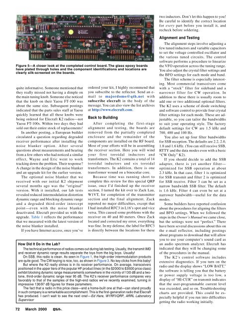
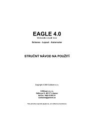
two inductors. Don’t let this happen to you!Be careful to identify the correct locationfor every part before you install it, andrecheck before soldering.Figure 5—A closer look at the completed control board. The glass epoxy boardshave plated through holes and the component identifications and locations areclearly silk-screened on the boards.quite informative. Someone mentioned thatthey really missed not having a dimple onthe main tuning knob. Someone else noticedthat the knob on their Yaesu FT-100 wasabout the same size. Subsequent postingsindicated that the parts sales staff at Yaesuquickly learned that all these knobs werebeing ordered for Elecraft K2 radios—notYaesu FT-100s. Within two days they hadsold out their entire stock of replacements!In another posting, a European buildercirculated a question regarding degradedreceiver performance after installing thenoise blanker option. After severalquestions about measurements and hearingfrom a few others who had noticed a similareffect, Wayne and Eric went to worktracking down the problem. Their response?A change in the design of the noise blankerand an upgrade kit for the earlier version.The optional noise blanker that wereceived with our initial K2 shipmentseveral months ago was the “original”version. With it installed, our lab testsrevealed reduced intermodulation distortiondynamic range and blocking dynamic rangeand a degraded third-order interceptpoint—even with the noise blankerdeactivated. Elecraft provided us with theupgrade. Table 1 reflects the performancethat we measured with the latest version ofthe noise blanker installed.If you have Internet access, once you’veordered your kit, I highly recommend thatyou subscribe to the reflector. Send an e-mail to majordomo@qth.net withsubscribe elecraft in the body of themessage. You can also view the list archivesat http://www.elecraft.com.Back to BuildingAfter completing the first-stagealignment and testing, the boards areremoved from the partially completedenclosure and the remainder of thecomponents are installed on the RF board.Most of your efforts will be in assemblingthe receiver section. Here you will windyour first toroidal inductors andtransformers. The K2 contains a total of 14toroidal inductors and six toroidaltransformers. In addition, there is onetransformer wound on a binocular core.Because time was running short tocomplete this review for this special QRPissue, once I’d finished up the receiversection, I turned the kit over to Zack Lau,W1VT, for completion of the transmittersection and the final alignment. Zackreported no major difficulties, except thatI had installed RFC3 in L16’s spot and viceversa. This caused some problems with thereceiver on 40 and 80 meters. Once Zacklocated and corrected my error, everythingwas fine. In my defense, the label for RFC3is directly between the locations for theseHow Did It Do in the Lab?The technical performance of radios comes out during lab testing. Usually, the transmit IMDand receiver dynamic range results separate the toys from the big boys. Usually!On SSB, this radio is clean. As seen in Figure 1, the high-order intermodulation productsare quite good. The CW keying is nice, too, as shown in Figure 3. No key clicks from this baby!But where the K2 really shines is in its receiver performance. On average, transceiverspositioned in the upper tiers of the popular HF product lines (in the $<strong>2000</strong> to $3500 price class)exhibit blocking dynamic range measurements somewhere in the vicinity of 130 dB and a twotone,third-order dynamic range near 95 dB. The K2’s receiver performance compares veryfavorably to that of the samples of the high-end radios we’ve recently examined, turning inimpressive 136/97 dB figures for these parameters.The fact that a radio in this price class—and a home-built one at that—can stand proudlyin such company is a remarkable accomplishment. This is the first-generation radio that Elecrafthas produced. I can’t wait to see the next one!—Ed Hare, W1RFI/QRP, ARRL LaboratorySupervisorAlignment and TestingThe alignment steps involve adjusting afew tuned inductors and variable capacitorsto set the voltage controlled oscillator andthe various tuned circuits. The controlsoftware performs a procedure to linearizethe VFO operation across the tuning range.You also adjust the crystal filter settings andthe BFO settings for each mode and band.The filter scheme is especially interesting.Most commercial transceivers comewith a “stock” filter for sideband and anarrower filter for CW operation. Inaddition to these there is usually room toadd one or two additional optional filters.The K2 uses a scheme of diode switchingand software control to provide four crystalfilter settings for each mode. These are adjustable,so you can tailor the bandwidthsto suit your operating style. The factorydefault settings for CW are 1.5 kHz and700, 400 and 100 Hz.You also set up four filter bandwidthsfor SSB reception. The defaults are 2.2, 2.0,1.8 and 1.6 kHz. (You can still receive SSB,RTTY and the data modes even with a basic“CW Only” K2).If you should decide to add the SSBadapter, there is yet another filter—optimized for SSB operation at about2.3 kHz. In that case, filter 1 is optimizedfor SSB transmit and filter 2 is optimizedfor SSB receive. Filter 3 can be set as anarrow bandwidth SSB filter. The defaultis 1.6 kHz. Filter 4 can even be set at anarrower bandwidth—useful for the datamodes.Some builders have reported confusionabout the procedures for aligning the filtersand BFO settings. When we followed thesteps in the Owner’s Manual we came close,but the settings were not “perfect.” Therehave been several discussions about this onthe e-mail reflector, including postingsabout programs to download that will allowyou to use your computer’s sound card asan audio spectrum analyzer. Elecraft hasindicated that they will be changing someof the procedures in the manual.The K2’s control software includesextensive diagnostics. If you turn on theradio and the display shows “LOW BATT,”the software is telling you that the batteryor power supply voltage is too low, adisplay of “HI-CUR” on transmit indicatesthat the user-programmable current levelwas exceeded, and so on. Troubleshootingcharts are provided. This could be especiallyhelpful if you run into difficultiesgetting the radio working initially.72 <strong>March</strong> <strong>2000</strong>
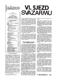
switched in.) This filter is optimized fornarrow bandwidths of about 200 to 500 Hz,but it can be adjusted wider or narrower ifdesired. A second two-pole crystal filterfollows the IF amplifier. This filter can alsobe tuned, but over a smaller bandwidthrange. The AGC signal is derived from theIF amp output using an auxiliary lowfrequency IF of about 150 kHz.Figure 6—An internal view with the top cover removed. The display and controlboard plug into the RF board along its front edge. Note the almost total absenceof point-to-point wiring. The rear apron is pre-punched for a wide variety ofavailable and proposed optional accessories.A Few Circuit DetailsThe K2 uses a modular design thatallows flexibility and opportunities forfuture expansion. The display boardprovides the user interface, including thedisplay and all the controls. The controlboard contains the main microprocessor, thedc control signal circuits, the AGC circuitand the audio amplifier. The RF boardserves as a “motherboard” for these twoboards and any optional boards. In additionto all the RF circuitry, this board containsthe I/O controller and the latching relaysthat select the operating band.The receiver is a single-conversionsuperheterodyne that employs double-tunedband-pass filters for each band. It uses adown-conversion scheme with an IF of4.915 MHz. The individual band-passfilters provide superior IMD performancewhen compared to up-converting designsthat often use a single low-pass filter toremove image products. Because the BFOis microprocessor controlled, its frequencyis reset for USB and LSB reception as wellas CW on either side of the carrier.In transmit, the signal flow reverses,with the output signal going through theband-pass and low-pass filters. The RFamplifier can produce over 10 W and isdesigned to provide good immunity to highSWR. PIN-diode T-R switching results insilent QSK operation.The microprocessor firmware controlsjust about every aspect of the K2’soperation. There are many routines that runbehind the scenes. For example, the PLLreference oscillator is linearized on eachband by an auto-calibration routine. Theresults of this routine are stored inEEPROM tables for use each time you turnon the radio. The firmware also supportsfeatures like built-in test equipment, amemory keyer, dual VFOs with splitoperation and frequency and band stackingmemories. Provisions are included for avariety of optional modules, such as theSSB adapter, the noise blanker, theautomatic antenna tuner and so on. Withjust 8 kilobytes of memory in the PIC16C77 microcontroller, it’s readily apparentthat the control program code has beenhighly optimized!The I/O controller is a coprocessor IC.The SSB adapter board carries its own coprocessor,as do some of the other optionalmodules. This has several effects. Itsimplifies the primary control circuitry andallows the accessory coprocessors to “goto sleep” when they aren’t needed, savingvaluable current for battery operation. Italso reduces the amount of digital noise onthe RF board that might cause receiverinterference.Speaking of saving battery current,several other power saving features areworth mention. The S meter/RF outputmeter LED bargraph can be set to bar, dotor off. The LCD display backlighting canbe turned off. With the LCD set fornighttime operation, the LED bargraphbrightness is reduced slightly and when theLCD is set for daytime operation the LEDbargraph is brighter to make it easier to see.Latching relays are used for all filter, VCOand option switching, so there is no relaycurrent drain during normal operation. Bycareful power management, the totalreceive current requirement can be as lowas about 150 mA. This is an order ofmagnitude lower than typical HFtransceivers.The K2 uses a PLL synthesizer IC and awide-range, band-switched voltagecontrolled oscillator. A 12-bit DAC givesthe fine-tuning steps on the VCO, which isthe PLL reference oscillator. Three DPDTlatching relays select one of eight VCOranges for the synthesizer.A 5-pole variable bandwidth crystalfilter is used in front of the IF stage. (Withthe SSB adapter, a separate fixed filter isThe Finished ProductThe completed K2 is an HF transceiverwith many of the features that we havecome to expect on the ready-builtcommercial rigs. The small-sized frontpanel has a nice ergonomic design thatallows my big clumsy fingers to find theright controls without knocking all the othersettings out of whack. The well-thought-outlayout results in very intuitive operation.The main tuning knob, in the center ofthe front panel, enjoys plenty of spacearound its perimeter. Four control knobs tothe left side of the front panel adjust thekeyer speed, the output power, the audiogain and the RF gain. One knob to the rightof the main tuning knob controls transmitand receive incremental tuning.The rest of the control operations arehandled by push-buttons. Each buttonserves two purposes—one when you tap itbriefly and another when you hold it in fora second. Labels above and below eachbutton indicate these functions.With these buttons you can step up ordown through the bands, directly punch infrequencies, store and recall memories (tenmemories are available), select the mode,choose VOX or PTT operation, switchbetween VFO A and B, equalize the VFOsettings, select split frequency operation,reverse the transmit/receive frequenciesmomentarily and automatically scan forCW signals over a programmable frequencyrange. You can also activate the preamplifierand RF attenuator, select the fast orslow AGC (and even turn the AGC off!),cycle through the filter options and enableRIT and/or XIT. The SPOT key turns on thesidetone oscillator during receive so thatyou can match the received tone of a CWsignal to your sidetone oscillator to ensurethat you are tuned to zero beat. CW RV letsyou listen on the opposite side of a signal.The MSG/REC button provides access tothe 9 message memories in the built-inelectronic keyer. Hold this button to beginthe memory record, then tap a number buttonand send the message you would like to store.When you pause for more than a few seconds(or if you tap the MSG/REC button again)recording stops. You play the memorycontents by tapping MSG/REC and then theappropriate number button. Messages canalso be repeated at a programmable internal.<strong>March</strong> <strong>2000</strong> 73
- Page 6 and 7:
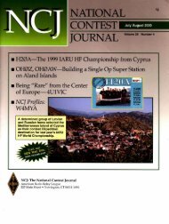
March 2000 Volume 84 Number 3David
- Page 11 and 12:
THE AMERICAN RADIORELAY LEAGUE INC
- Page 14:
Get to Know Your Section ManagerThe
- Page 18:
Senate CommerceChairman andPresiden
- Page 22 and 23:
GEORGE DOMINICK, W4UWCLooking for a
- Page 26 and 27: CORRESPONDENCEYour opinions count!
- Page 30 and 31: By Stephen Stuntz, N0BFImagine ridi
- Page 32 and 33: By David A. Rosenthal, N6TSTDXing W
- Page 34 and 35: It was a ham’s dream, sitting onM
- Page 36 and 37: always start at the beginning of me
- Page 38 and 39: An insideview of theQRSerprototype.
- Page 40 and 41: Kits and BoardsWhile the original T
- Page 42 and 43: TT2 PerformanceKeying quality with
- Page 44 and 45: Figure 1—Schematic of the meter-m
- Page 46 and 47: Figure 1—Schematic of the Simple
- Page 48 and 49: tacts I had while using this transm
- Page 50 and 51: chandisers are free to develop “s
- Page 52 and 53: WORKBENCHPROJECTS AND INFORMATION F
- Page 54 and 55: THE HELP DESKSchematic Symbols52 Ma
- Page 56 and 57: paddle. This can be done with eithe
- Page 58 and 59: creator) was providing free PSK31 s
- Page 60 and 61: By H. Ward Silver, N0AXTest Your Kn
- Page 62 and 63: HINTS & KINKSA SIMPLE ANTENNA FLIPP
- Page 64 and 65: By Dave Patton, NT1N2000 Annual Mee
- Page 66 and 67: The Board welcomed three new Vice D
- Page 68 and 69: Craigie nominated Mr. Butler. Mr. B
- Page 70 and 71: D.C., with the specific responsibil
- Page 72 and 73: Table 1Elecraft K2, serial number 0
- Page 76 and 77: Like most transceivers these days,
- Page 78 and 79: Table 2Alinco DJ-V5TH, serial numbe
- Page 80 and 81: FCC NewsENHANCED AMATEUR ENFORCEMEN
- Page 82 and 83: tem is not legal to use as it’s c
- Page 84 and 85: chance to do it. It may be several
- Page 86 and 87: officials and the hundreds of train
- Page 88 and 89: THE WORLD ABOVE 50 MHZDr. Ernest K.
- Page 90 and 91: EME AnnalsEME (moonbounce) standing
- Page 92 and 93: DIGITAL DIMENSIONWinLink 2000: A Wo
- Page 94 and 95: From the Mailbag…Throughout the y
- Page 96 and 97: AT THE FOUNDATIONSpringing with New
- Page 98 and 99: (156.7 Hz), 146.52. Adm: $2. Tables
- Page 100 and 101: It is with deep regret that we reco
- Page 102 and 103: CONTEST CORRALFeedbackIn the 1999 A
- Page 104 and 105: By Dan Henderson, N1NDContest Branc
- Page 106 and 107: Affiliated Club Competition Results
- Page 108 and 109: 1999 IARU HF WorldChampionship Resu
- Page 110 and 111: N5XU (+KA5WSS,KM5FA,N3TNN)390,104 8
- Page 112 and 113: RW4AA 1,299,804 2121 172 ARW3GU 879
- Page 114 and 115: Revised 1999 June VHF QSO Party Rov
- Page 122: has been around for some time, is a
- Page 126:
154, WB5ZED 232. Tfc: K5WOD 4, NOKW
- Page 130:
Bethpage, NY. Bob Wexelbaum, W2ILP,
- Page 134:
NEW HAMPSHIRE: SM, Mike Graham, K7C
- Page 138:
136longtime member N6DOC. Installat
- Page 142:
tion of the digital network within
- Page 146:
DEC, EC, ASM, and cabinet member at
- Page 150:
148agencies have had a working rela
- Page 156:
CALL SIGN NAME BADGES. Club logos o
- Page 160:
COMPUTERS - WANTED early Pre-1980 m
- Page 176:
Index of AdvertisersADVERTISING DEP