paddle. This can be done with either the edge of a small file or witha hacksaw. Cut just enough to be sure you have separated thecopper foil nicely. What you are doing is creating the switch contactpads for the dit and dah sides of the paddle. It is necessary tocut the foil in two places on each side of the paddle, as shown inthe drawings, so that static electricity and other stray electricalcurrents from your skin won’t cause erratic keying.The tension adjustment hole in the paddle is enlarged (therebyremoving material from the paddle itself) to provide whateverspring tension you desire. This is done before the phono jacks andconnecting wires to the switch pads are installed, and after thepaddle set itself is soldered together and the adjustment screws areinstalled and adjusted for whatever switch gap feels good to you.So, initially, cut about a 1 /8-inch hole.Assemble the PaddlesFirst, set the rear frame in place, centered and about a quarterinch in from one end of the base, and tack solder one lower edgeof the rear frame to the base. Check visually for proper placementand make sure that the rear frame is perpendicular to the base. Heatthe solder tack, move the rear frame as necessary with a finger, andlet the solder tack cool. Then tack the other side before running abead of solder all along each lower side of the rear frame.When you are running a bead of solder between two surfaceswhich are at 90º angles, the trick is to prop the unit up so that the twosurfaces form a V, with the apex at the bottom and the two sides about45º from the vertical. This way, the melted solder will run along bothsides of the joint, and form a strong, nice-looking connection.Next, solder one 4-40 nut to one side of each adjustment screwsupport. The trick to doing this is to screw the nut onto a screw, putthe end of the screw through the hole in the support, rest the supportin a horizontal position, heat the nut and its adjoining copper foil,and wick the solder underneath the nut. Once the nut has been solderedin place, and the unit has cooled, simply unscrew the screwfrom the nut, and do the same operation on the other support.Position the two adjustment screw supports on the paddle baseand solder them into place. The trick to positioning them is toscrew the one-inch long 4-40 brass screw through both supports,leaving about 3 /8 inch between the two soldered-on nuts, whichshould be on the inside of each support, facing each other. Use thepaddle as a guide to how far away from the rear frame to positionthe supports. The front edge of the supports should be about evenwith the foil cuts separating the finger-contact portions of thepaddle from the switch pads. The far end of the paddle, with thetension hole in it, will butt up against the rear frame, and after theadjustment screw supports are soldered in place and the one-inchscrew removed, it will be installed permanently.The adjustment screw supports should be soldered along bothlower sides of each support. Again, tack solder one side, then theother, and then run a bead of solder along the lower edge of each.This will ensure that they don’t move during the soldering process.Next, remove the one inch screw from the adjustment screwsupports, install the two lock nuts, one on each screw, running thelock nuts right up to the screw heads, and screw the adjustmentscrews into their respective supports. Leave enough space betweenthe two to fit the paddle between them.Place the paddle in position between the two adjustment screwsand butted up against the rear frame. The lower edge of the paddleshould be at least 1 /16-inch above the surface of the base.Finger tighten the two adjustment screws against the paddle,which will hold the paddle pretty well in position while you thentack solder each side of the paddle against the rear frame. Run abead of solder along the edge of each side of the paddle where itbutts against the rear frame.Now loosen the two adjustment screws slightly and adjust themfor whatever switch gap feels good to you. Tighten the lock nutsto maintain that gap.Before installing the two phono jacks and the two short piecesof hookup wire that connect from the center of each to their respectiveswitch pads, open up the tension adjustment hole as desired.Remove material a little at a time until you have whateverpaddle spring tension feels good to you. Remember that you canalways remove more material. It is hard to put it back.When you have the paddle spring tension set to your liking,install the two phono jacks and solder the two short pieces ofhookup wire to the center connections of each and to their respectiveswitch pads. Remember to leave a small amount of slack ineach wire so that the paddle can move easily.Hooking It UpYou will need a three wire cable (or two shielded audio cableswith a stereo miniature phone plug installed on one end and twophono plugs on the other) to run from the paddle set to your keyeror rig. For my own installation I used a pair of shielded audiocables. I cut the phono plugs from one end of each and installed astereo miniature phone plug, soldering the shield of each audiocable to the ground connection of the plug—one center wire to thering connection and one to the tip connection of the plug.Before you install the stereo plug, cut several short ( 3 /16 inch)lengths of the outer insulation from some scrap RG-58 or 59 (orRG-8X or whatever you have) and slip these over the two audiocables, spacing them about every three inches. These make greatcable ties and they look good with black audio cables.That’s all there is to it! You now have a portable, small, lightweightand, best of all, cheap set of paddles.OperationTop view of theNB6M paddles.I operate my paddles by holding the set in the palm of one handand working them with the thumb and forefinger of the other. Alternatively,you could hold the paddle set down on a tabletop with yourmiddle finger placed over the junction of paddle and rear frame, andthe tip of your forefinger placed next to the adjustment screw supporton the near side of the paddle base. This leaves plenty of room tooperate the paddle with the thumb and forefinger of the other hand.Enjoy!909 Marina Village, #163Alameda, CA 94501; nb6m@mcr.win-net.orgSide view. Noticehow the copper foilhas been cut tocreate a switch pad.54 <strong>March</strong> <strong>2000</strong>
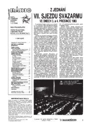
By Timothy P. Hulick, W9QQPSK31 on the Road!Forget your RTTY gear the last time you cruised cross-country? Thanks to theincredible weak-signal performance of PSK31—and a few choice macros—you can take it with you!learned to enjoy mobile DXing as a kid in the ’50s. MyIparents’ 1955 Oldsmobile 98 made the perfect shack onwheels. That’s way back when there really wasn’t anyequipment specifically designed for mobile work. Mobileequipment should be small, lightweight and dc-powered. Thattechnology hadn’t yet been born, and big and heavy was the nameof the game.The bigger it was, the heavier it was, the better it was. That wasthe image of the proverbial mobile rock crusher. A high-voltagepower supply with a 12-V dc input was nearly impossible to findor build because the solid-state devices necessary to support thedesign of something like that just didn’t exist.The predecessor of the modern high-voltage switching powersupply was the WW II surplus dynamotor. They were abundant inthose days and rather inexpensive. One dynamotor easily providedthe 800 V necessary to run a 100-W power amplifier—butnot without the occasional dead battery if the QSO dragged on toolong (5-10 minutes if the engine was turned off).If I remember correctly, the 12-V current drain was somewherebetween 20 and 30 A, plus the motor start-up current required eachtime the PTT button was pressed. As a teenager I lost my drivingprivileges more than once because of unexplained dead batteries.“What dead battery? I didn’t do it!”Full-carrier AM wasn’t effective in busting pileups from thecar—at least not in the dynamotor era! On hot summer days, idlingthe engine was out of the question. That brought along its own setof problems. Reliving the glory days of HF mobiling is fun, butI’m glad that dynamotors are ancient history. Mobile DXing haschanged dramatically.A Mobile TraditionI’ve always had an HF rig in the car, especially after it reallybecame practical. Heath’s line of compact monoband rigs, debutingin the ’60s and early ‘70s, were just what the hobby ordered.I just had to have one for each of the bands on which they wereavailable (80, 40 and 20 meters). I even coaxed the 80-meter versiononto 15 meters because my main objective was to “work DXfrom the car.” It was my ultimate challenge.The modifications were productive and I worked a lot of DX on15 and 20 meters. But because the rigs were monobanders, changingbands meant changing transceivers! Even worse, there was no wayto fight the incredible level of ignition noise that tended to plaguemobile ops in those days. Noise blankers weren’t exactly stock items.My trusty dynamotor was replaced with a Heath solid-stateswitching supply that was far more efficient. I never did end upwith a dead battery while using Heathkit’s model HP-13. I stillhave the thing. It works fine, although I gave the transceiversaway years ago.In the mid-1970s, along came the Atlas 210X. That was theThe author pulls over at a promising location, switches onhis transceiver, opens his laptop computer and works PSK31.first real all-solid-state rig designed for 12 V. It didn’t need a highvoltagesupply of any kind. It was truly the predecessor to today’sultra-compact mobile rigs. It was small, lightweight and great forHF SSB on the move. The best DX I worked with that little rig wasa ZS6 in the spring of 1983 on 15 meters.Today I use a Kenwood TS-440S with a center-loaded whipantenna and have managed to confirm 143 countries since I startedcounting in the early ‘80s. Working DX has become commonplace,especially on 15 meters (the antenna is noticeably moreefficient there).PSK31 on the GoI’ve heard that old-timers such as W6AM used to operate CWwhile mobile on California’s freeways, but somehow that neverappealed to me. I’m not sure I could drive the car, interpret CWand chew gum at the same time.Operating PSK31 under the same conditions is no better, butduring stopovers on long trips, or at least during an overnight stay,PSK31 is just the ticket to great operating opportunities awayfrom home. There are several reasons why. PSK31 is an excellentlow-power mode, and a laptop computer with a suitable soundsystem is the only additional hardware needed.I was introduced to PSK31 in February of 1999 when I workedHB9BRJ on Baudot. Markus said that a new BPSK/QPSK modewas catching on in Europe. Now, BPSK and QPSK aren’t entirelynew, but they were new to Amateur Radio, and G3PLX (PSK31’s<strong>March</strong> <strong>2000</strong> 55
- Page 6 and 7: March 2000 Volume 84 Number 3David
- Page 11 and 12: THE AMERICAN RADIORELAY LEAGUE INC
- Page 14: Get to Know Your Section ManagerThe
- Page 18: Senate CommerceChairman andPresiden
- Page 22 and 23: GEORGE DOMINICK, W4UWCLooking for a
- Page 26 and 27: CORRESPONDENCEYour opinions count!
- Page 30 and 31: By Stephen Stuntz, N0BFImagine ridi
- Page 32 and 33: By David A. Rosenthal, N6TSTDXing W
- Page 34 and 35: It was a ham’s dream, sitting onM
- Page 36 and 37: always start at the beginning of me
- Page 38 and 39: An insideview of theQRSerprototype.
- Page 40 and 41: Kits and BoardsWhile the original T
- Page 42 and 43: TT2 PerformanceKeying quality with
- Page 44 and 45: Figure 1—Schematic of the meter-m
- Page 46 and 47: Figure 1—Schematic of the Simple
- Page 48 and 49: tacts I had while using this transm
- Page 50 and 51: chandisers are free to develop “s
- Page 52 and 53: WORKBENCHPROJECTS AND INFORMATION F
- Page 54 and 55: THE HELP DESKSchematic Symbols52 Ma
- Page 58 and 59: creator) was providing free PSK31 s
- Page 60 and 61: By H. Ward Silver, N0AXTest Your Kn
- Page 62 and 63: HINTS & KINKSA SIMPLE ANTENNA FLIPP
- Page 64 and 65: By Dave Patton, NT1N2000 Annual Mee
- Page 66 and 67: The Board welcomed three new Vice D
- Page 68 and 69: Craigie nominated Mr. Butler. Mr. B
- Page 70 and 71: D.C., with the specific responsibil
- Page 72 and 73: Table 1Elecraft K2, serial number 0
- Page 74 and 75: two inductors. Don’t let this hap
- Page 76 and 77: Like most transceivers these days,
- Page 78 and 79: Table 2Alinco DJ-V5TH, serial numbe
- Page 80 and 81: FCC NewsENHANCED AMATEUR ENFORCEMEN
- Page 82 and 83: tem is not legal to use as it’s c
- Page 84 and 85: chance to do it. It may be several
- Page 86 and 87: officials and the hundreds of train
- Page 88 and 89: THE WORLD ABOVE 50 MHZDr. Ernest K.
- Page 90 and 91: EME AnnalsEME (moonbounce) standing
- Page 92 and 93: DIGITAL DIMENSIONWinLink 2000: A Wo
- Page 94 and 95: From the Mailbag…Throughout the y
- Page 96 and 97: AT THE FOUNDATIONSpringing with New
- Page 98 and 99: (156.7 Hz), 146.52. Adm: $2. Tables
- Page 100 and 101: It is with deep regret that we reco
- Page 102 and 103: CONTEST CORRALFeedbackIn the 1999 A
- Page 104 and 105: By Dan Henderson, N1NDContest Branc
- Page 106 and 107:
Affiliated Club Competition Results
- Page 108 and 109:
1999 IARU HF WorldChampionship Resu
- Page 110 and 111:
N5XU (+KA5WSS,KM5FA,N3TNN)390,104 8
- Page 112 and 113:
RW4AA 1,299,804 2121 172 ARW3GU 879
- Page 114 and 115:
Revised 1999 June VHF QSO Party Rov
- Page 122:
has been around for some time, is a
- Page 126:
154, WB5ZED 232. Tfc: K5WOD 4, NOKW
- Page 130:
Bethpage, NY. Bob Wexelbaum, W2ILP,
- Page 134:
NEW HAMPSHIRE: SM, Mike Graham, K7C
- Page 138:
136longtime member N6DOC. Installat
- Page 142:
tion of the digital network within
- Page 146:
DEC, EC, ASM, and cabinet member at
- Page 150:
148agencies have had a working rela
- Page 156:
CALL SIGN NAME BADGES. Club logos o
- Page 160:
COMPUTERS - WANTED early Pre-1980 m
- Page 176:
Index of AdvertisersADVERTISING DEP