

30HZ/HZV 043-280 Water-Cooled/Condenserless Liquid Chillers
30HZ/HZV 043-280 Water-Cooled/Condenserless Liquid Chillers
30HZ/HZV 043-280 Water-Cooled/Condenserless Liquid Chillers

You also want an ePaper? Increase the reach of your titles
YUMPU automatically turns print PDFs into web optimized ePapers that Google loves.
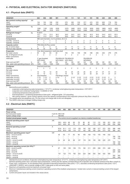
4 - PHYSICAL AND ELECTRICAL DATA FOR <strong>30HZ</strong>/<strong>HZV</strong> (R407C/R22)4.1 - Physical data (R407C)<strong>30HZ</strong>/<strong>HZV</strong> <strong>043</strong> 052 065 091 101 111 121 141 161 195 225 250 <strong>280</strong>Net nominal cooling capacity* kW<strong>30HZ</strong> 134 153 199 230 270 300 316 371 415 533 626 719 783<strong>30HZ</strong>V 126 144 194 216 260 278 297 352 388 500 588 677 735Operating weight**kg<strong>30HZ</strong> 1090 1183 1252 2039 2370 2460 2510 2730 2830 3505 3805 4470 4900<strong>30HZ</strong>V 880 968 1018 1672 1960 2000 2040 2260 2300 2975 3267 3780 4106Refrigerant charge*** kg R-407CCircuit A 15.7 17.5 21.0 38.2 29.5 34.5 33.5 38.0 42.0 54.0 54.0 62.5 62.5Circuit B 15.7 17.5 21.0 19.5 29.5 29.5 33.5 38.0 42.0 46.5 54.0 60.5 62.5Compressors06E semi-hermetic, 4 or 6 cylinders, 24.2 r/sQuantity - Circuit A 1 1 1 2 2 2 2 2 2 3 3 4 4Quantity - Circuit B 1 1 1 1 2 2 2 2 2 2 3 3 4Capacity controlPRO-DIALOG Plus controlNo. of control steps 4 4 4 6 11 11 11 11 11 5 6 7 8Minimum step capacity % 40 33 33 22 20 18 16 19 16 20 16 14 12EvaporatorOne, direct expansion, multi-tube shellNet water volume l 55 63 63 92 154 154 154 199 199 242 242 276 276No. of refrigerant circuits 2 2 2 2 2 2 2 2 2 2 2 2 2<strong>Water</strong> connectionsInlet/outlet 3” gas threaded PN16DN100 PN16DN125 PN16DN150NFE 03005 NFE 29203 NFE 29203 NFE29203Drain and vent NPT in 3/8 3/8 3/8 3/8 3/8 3/8 3/8 3/8 3/8 3/8 3/8 3/8 3/8Max. water-side operating pressure kPa 1000 1000 1000 1000 1000 1000 1000 1000 1000 1000 1000 1000 1000CondenserShell and multi-tubeQuantity 2 2 2 2 2 2 2 2 2 2 2 2 2Net water volumelCircuit A 10 10 12 25 18 25 25 25 30 37 37 51 51Circuit B 10 10 12 12 18 18 25 25 30 30 37 37 51<strong>Water</strong> connections in Gas threaded Flat flange, brazedInlet/outlet, circuit A 1-1/2 1-1/2 2 2-1/2 2 2-1/2 2-1/2 2-1/2 2-1/2 2-1/2 2-1/2 3 3Inlet/outlet, circuit B 1-1/2 1-1/2 2 2 2 2 2-1/2 2-1/2 2-1/2 2-1/2 2-1/2 2-1/2 3Drain and vent NPT in 3/8 3/8 3/8 3/8 3/8 3/8 3/8 3/8 3/8 3/8 3/8 3/8 3/8Max. water-side operating pressure kPa 1000 1000 1000 1000 1000 1000 1000 1000 1000 1000 1000 1000 1000Notes:* Nominal Eurovent conditions:- evaporator entering/leaving water temperature = 12°C/7°C, condenser entering/leaving water temperature = 30°C/35°C- evaporator and condenser fouling factor = 0.000044 m 2 K/W- condensing temperature dew point 45°C- fluid temperature = condensing temperature at dew point - refrigerant glide - 5 K subcooling.- Net cooling capacity = gross cooling capacity minus the capacity corresponding to the evaporator pressure drop (flow x drop/0.3)** The weights given are guidelines only. For the correct unit charge refer to the unit nameplate.*** The <strong>30HZ</strong>V units have a nitrogen holding charge only.4.2 - Electrical data (R407C)<strong>30HZ</strong>/<strong>HZV</strong> <strong>043</strong> 052 065 091 101 111 121 141 161 195 225 250 <strong>280</strong>Power wiringNominal power supply V-ph-Hz 400-3-50System voltage range V 360-440Control circuit power supplyThe control circuit is supplied via a factory-installed transformer.Nominal operating power input*kW<strong>30HZ</strong> 38.5 48.9 68 69 78 86 92 112 131 165 201 239 270<strong>30HZ</strong>V 38.5 48.6 65 70 77 86 94 112 135 165 200 234 266Nominal operating current*A<strong>30HZ</strong> 63.8 81.1 112 114 129 142 152 185 217 273 333 396 448<strong>30HZ</strong>V 63.8 80.6 108 116 127 142 156 185 224 273 332 388 441Maximum operating power input**kW<strong>30HZ</strong> – circuit A and B 45 55 77 82 90 100 109 132 155 194 232 - -<strong>30HZ</strong> – circuit A - - - - - - - - - - - 155 155<strong>30HZ</strong> – circuit B - - - - - - - - - - - 116 155<strong>30HZ</strong>V – circuit A and B 54 65 90 98 107 119 130 155 180 225 270 - -<strong>30HZ</strong>V – circuit A - - - - - - - - - - - 180 180<strong>30HZ</strong>V – circuit B - - - - - - - - - - - 135 180Maximum operating current (Un-10%)***A<strong>30HZ</strong> – circuit A and B 87 105 150 158 174 192 211 255 299 374 449 - -<strong>30HZ</strong> – circuit A - - - - - - - - - - - 299 299<strong>30HZ</strong> – circuit B - - - - - - - - - - - 224 299<strong>30HZ</strong>V – circuit A and B 101 123 170 185 203 224 246 293 340 425 509 - -<strong>30HZ</strong>V – circuit A - - - - - - - - - - - 340 340<strong>30HZ</strong>V – circuit B - - - - - - - - - - - 255 340* Standard Eurovent conditions: Evaporator entering/leaving water temperature 12°C/7°C, condenser entering/leaving water temperature 30°C/35°C.Nominal operating power input: unit power input (compressors, control) plus the capacity corresponding to the evaporator and condenser pressure drop (flow x drop/0.3).** Power input, compressors, at unit operating limits (saturated evaporating temperature (dew point) = 12°C, saturated condensing temperature (dew point) = 52°C(<strong>30HZ</strong>)/66°C (<strong>30HZ</strong>V), and a nominal voltage of 400 V (data given on the unit name plate).*** Maximum unit operating current at maximum unit power input.† Maximum instantaneous starting current (maximum operating current of the smallest compressor(s) + locked rotor current or reduced starting current of the largestcompressor).‡ Current and power inputs not included in the values above.10


