

30HZ/HZV 043-280 Water-Cooled/Condenserless Liquid Chillers
30HZ/HZV 043-280 Water-Cooled/Condenserless Liquid Chillers
30HZ/HZV 043-280 Water-Cooled/Condenserless Liquid Chillers

Create successful ePaper yourself
Turn your PDF publications into a flip-book with our unique Google optimized e-Paper software.
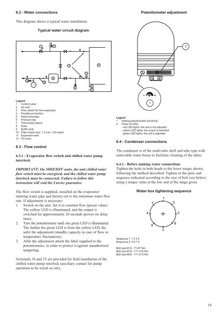
6.2 - <strong>Water</strong> connectionsPotentiometer adjustmentThis diagram shows a typical water installation.Typical water circuit diagram1 224 531211109867Legend1 Control valve2 Air vent3 Flow switch for the evaporator4 Flexible connection5 Heat exchanger6 Pressure tap7 Thermostat sleeve8 Drain9 Buffer tank10 Filter (mesh size: 1.2 mm = 20 mesh)11 Expansion tank12 Fill valve6.3 - Flow control6.3.1 - Evaporator flow switch and chilled water pumpinterlockIMPORTANT: On <strong>30HZ</strong>/<strong>HZV</strong> units, the unit chilled waterflow switch must be energised, and the chilled water pumpinterlock must be connected. Failure to follow thisinstruction will void the Carrier guarantee.The flow switch is supplied, installed on the evaporatorentering water pipe and factory-set to the minimum water flowrate. If adjustment is necessary:1. Switch on the unit. Set it to constant flow (preset value).The yellow LED is illuminated, and the output isswitched for approximately 20 seconds (power-on delaytime).2. Turn the potentiometer until one green LED is illuminated.The further the green LED is from the yellow LED, thesafer the adjustment (standby capacity in case of flow ortemperature fluctuations).3. After the adjustment attach the label supplied to thepotentiometer, in order to protect it against unauthorisedtampering.Terminals 34 and 35 are provided for field installation of thechilled water pump interlock (auxiliary contact for pumpoperation to be wired on site).Legend1 Setting potentiometer sensitivity2 Chain of LEDs- red LED lights: the unit is not adjusted- yellow LED lights: the output is switched- green LED lights: the unit is adjusted6.4 - Condenser connections1The condenser is of the multi-tube shell and tube type withremovable water boxes to facilitate cleaning of the tubes.6.4.1 - Before making water connectionsTighten the bolts in both heads to the lower torque shown,following the method described. Tighten in the pairs andsequence indicated according to the size of bolt (see below)using a torque value at the low end of the range given.Sequence 1: 1 2 3 4Sequence 2: 5 6 7 8<strong>Water</strong> box tightening sequence4Bolt size M12 - 71-87 NmBolt size M16 - 171-210 NmBolt size M20 - 171-210 Nm761258319


