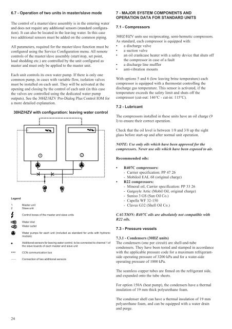
6.7 - Operation of two units in master/slave modeThe control of a master/slave assembly is in the entering waterand does not require any additional sensors (standard configuration).It can also be located in the leaving water. In this casetwo additional sensors must be added on the common piping.All parameters, required for the master/slave function must beconfigured using the Service Configuration menu. All remotecontrols of the master/slave assembly (start/stop, set point,load shedding etc.) are controlled by the unit configured asmaster and must only be applied to the master unit.Each unit controls its own water pump. If there is only onecommon pump, in cases with variable flow, isolation valvesmust be installed on each unit. They will be activated at theopening and closing by the control of each unit (in this casethe valves are controlled using the dedicated water pumpoutputs). See the <strong>30HZ</strong>/<strong>HZV</strong> Pro-Dialog Plus Control IOM fora more detailed explanation.<strong>30HZ</strong>/<strong>HZV</strong> with configuration: leaving water control7 - MAJOR SYSTEM COMPONENTS ANDOPERATION DATA FOR STANDARD UNITS7.1 - Compressors<strong>30HZ</strong>/<strong>HZV</strong> units use reciprocating, semi-hermetic compressors.As standard, each compressor is equipped with:• a discharge valve• a suction valve• an oil crankcase heater with a safety device that shuts offthe compressor in case of a fault• a discharge line muffler• anti-vibration mountsWith options 5 and 6 (low leaving brine temperature) eachcompressor is equipped with a thermostat controlling thedischarge gas temperature. This sensor is activated, if thetemperature exceeds the safety limit and shuts off thecompressor (cut-out: 146°C - cut-in: 115°C).7.2 - LubricantThe compressors installed in these units have an oil charge (9l) to ensure their correct operation.Check that the oil level is between 1/8 and 3/8 up the sightglass before start-up and after normal unit operation.NOTE: Use only oils which have been approved for thecompressors. Never use oils which have been exposed to air.1 2Recommended oils:Legend1 Master unit2 Slave unitControl boxes of the master and slave units<strong>Water</strong> inlet<strong>Water</strong> outlet<strong>Water</strong> pumps for each unit (included as standard for units with hydronicmodule)Additional sensors for leaving water control, to be connected to channel 1 ofthe slave boards of each master and slave unitCCN communication busConnection of two additional sensors• R407C compressors:- Carrier specification: PP 47 26- Mobiloil EAL 68 (original charge)• R22 compressors:- Mineral oil, Carrier specification: PP 33 26- Gargoyle Artic (Mobil Oil, original charge)- Suniso 3 GS (Sun Oil Co.)- Capella WF 32-150- Clavus G32 (Shell Oil Co.)CAUTION: R407C oils are absolutely not compatible withR22 oils.7.3 - Pressure vessels7.3.1 - Condensers (<strong>30HZ</strong> units)The condensers (one per circuit) are shell-and-tubecondensers. They have been tested and stamped in accordancewith the applicable pressure code for a maximum refrigerantsideoperating pressure of 3200 kPa and for a water-sideoperating pressure of 1000 kPa.The seamless copper tubes are finned on the refrigerant side,and expanded onto the tube sheets.For option 150A (heat pump), the condensers have a thermalinsulation of 19 mm thick polyurethane foam.The condenser shell can have a thermal insulation of 19 mmpolyurethane foam, and can be equipped with a water drainand purge.24
7.3.2 - EvaporatorThe evaporator is a shell-and-tube type with two refrigerantcircuits. It has been tested and stamped in accordance withapplicable pressure codes for a maximum operating pressureof 2100 kPa refrigerant-side and 1000 kPa water-side. Theseam-less copper tubes are finned on the refrigerant side andexpanded onto the tube sheets.The heat exchanger shell has a thermal insulation of 19 mmpolyurethane foam, and is equipped with a water drain andpurge.The products that may be added for thermal insulation of thecontainers during the water piping connection procedure mustbe chemically neutral in relation to the materials and coatingsto which they are applied. This is also the case for the productsoriginally supplied by Carrier s.a.NOTES: Monitoring during operation, re-qualification, retestingand re-testing dispensation:- Follow the regulations on monitoring pressurisedequipment.- It is normally required that the user or operator sets upand maintains a monitoring and maintenance file.- Follow the control programmes of EN 378-2, annexes A,B, C and D.- If they exist follow local professional recommendations.- Regularly inspect the condition of the coating (paint) todetect blistering resulting from corrosion. To do this,check a non-insulated section of the container or therust formation at the insulation joints.- Regularly check for possible presence of impurities (e.g.silicon grains) in the heat exchange fluids. These impuritiesmaybe the cause of the wear or corrosion by puncture.- Filter the heat exchange fluid check and carry outinternal inspections as described in EN 378-2, annex C.- In case of re-testing take possible maximum pressuredifferences, as indicated in (2) above into consideration.- The reports of periodical checks by the user or operatormust be included in the supervision and maintenancefile.RepairAny repair or modification, including the replacement ofmoving parts:- must follow local regulations and be made by qualifiedoperators and in accordance with qualified procedures,including changing the heat exchanger tubes- must be made in accordance with the instructions of theoriginal manufacturer. Repair and modification thatnecessitate permanent assembly (soldering, welding,expanding etc.) must be made using the correctprocedures and by qualified operators.- An indication of any modification or repair must beshown in the monitoring and maintenance file.RecyclingThe unit is wholly or partly recyclable. After use it containsrefrigerant vapours and oil residue. It is coated by paint.Operating lifeThis unit is designed for:- prolonged storage of 15 years under nitrogen chargewith a temperature difference of 20 K per day.- 710000 cycles (start-ups) with a maximum difference of6 K between two neighbouring points in the container,based on 6 start-ups per hour over 15 years at a usagerate of 90%.Excess corrosion thicknessGas side: 0 mmHeat exchange fluid side: 1 mm for tubular plates in lightlyalloyed steels, 0 mm for stainless steel plates or plates withcopper-nickel or stainless steel protection.7.4 - Electronic expansion device (EXV)These are an option for sizes <strong>30HZ</strong>/<strong>HZV</strong> <strong>043</strong>-065.The microprocessor controls the EXD through the EXV boardmodule. Inside this EXV is a linear actuator stepper motor.The stepper motor moves in increments and is controlleddirectly by the processor module. As the stepper motor rotates,motion is transferred into linear movement by the lead screw.Through the stepper motor and lead screws, 1500 discretesteps of motion are obtained. The large number of steps andlong stroke result in very accurate control of refrigerant flow.At initial start-up, the EXV position is at zero. After that, themicroprocessor keeps accurate track of the valve position inorder to use this information as input for the other controlfunctions. It does this by initializing the EXV’s at startup. Theprocessor sends out enough closing pulses to the valve to moveit from fully open to fully closed, then resets the positioncounter to zero. From this point on, until the initialization, theprocessor counts the total number of open and closed steps ithas sent to each valve.7.5 - Refrigerant<strong>30HZ</strong>/<strong>HZV</strong> standard units operate with refrigerant R407C.Optionally (option 7A) the units can use R22.7.6 - High-pressure safety switch<strong>30HZ</strong>/<strong>HZV</strong> units are equipped with a high-pressure safetyswitch, calibrated to 2700 kPa for <strong>30HZ</strong> units and 2900 kPa for<strong>30HZ</strong>V units.This switch is located on the central block of each lead compressor.7.7 - Moisture indicatorLocated on the liquid line, permits control of the unit chargeand indicates moisture in the circuit. The presence of bubblesin the sight-glass indicates an insufficient charge or noncondensablesin the system. The presence of moisture changesthe colour of the indicator paper in the sight-glass.7.8 - Filter drierThe role of the filter drier is to keep the circuit clean andmoisture-free. The moisture indicator shows, when it isnecessary to change the elements. A difference in temperaturebetween the filter inlet and outlet shows that the elements aredirty.25