

30HZ/HZV 043-280 Water-Cooled/Condenserless Liquid Chillers
30HZ/HZV 043-280 Water-Cooled/Condenserless Liquid Chillers
30HZ/HZV 043-280 Water-Cooled/Condenserless Liquid Chillers

You also want an ePaper? Increase the reach of your titles
YUMPU automatically turns print PDFs into web optimized ePapers that Google loves.
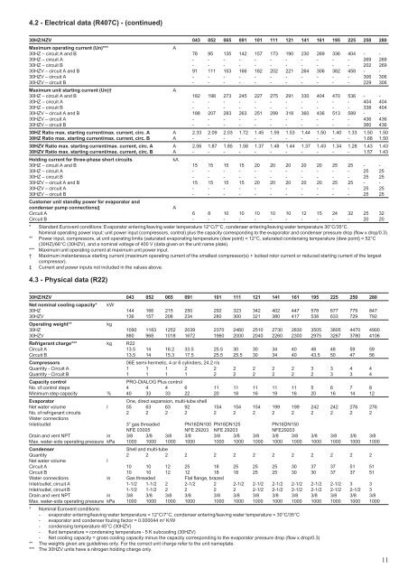
4.2 - Electrical data (R407C) - (continued)<strong>30HZ</strong>/<strong>HZV</strong> <strong>043</strong> 052 065 091 101 111 121 141 161 195 225 250 <strong>280</strong>Maximum operating current (Un)***A<strong>30HZ</strong> – circuit A and B 78 95 135 142 157 173 190 230 269 336 404 - -<strong>30HZ</strong> – circuit A - - - - - - - - - - - 269 269<strong>30HZ</strong> – circuit B - - - - - - - - - - - 202 269<strong>30HZ</strong>V – circuit A and B 91 111 153 166 182 202 221 264 306 382 458 - -<strong>30HZ</strong>V – circuit A - - - - - - - - - - - 306 306<strong>30HZ</strong>V – circuit B - - - - - - - - - - - 229 306Maximum unit starting current (Un)†A<strong>30HZ</strong> – circuit A and B 182 198 273 245 227 275 291 330 404 470 536 - -<strong>30HZ</strong> – circuit A - - - - - - - - - - - 404 404<strong>30HZ</strong> – circuit B - - - - - - - - - - - 338 404<strong>30HZ</strong>V – circuit A and B 188 207 283 263 251 299 318 360 436 513 589 - -<strong>30HZ</strong>V – circuit A - - - - - - - - - - - 436 436<strong>30HZ</strong>V – circuit B - - - - - - - - - - - 360 436<strong>30HZ</strong> Ratio max. starting current/max. current, circ. A A 2.33 2.09 2.03 1.72 1.45 1.59 1.53 1.44 1.50 1.40 1.33 1.50 1.50<strong>30HZ</strong> Ratio max. starting current/max. current, circ. B A - - - - - - - - - - - 1.68 1.50<strong>30HZ</strong>V Ratio max. starting current/max. current, circ. A A 2.06 1.87 1.85 1.58 1.37 1.48 1.44 1.37 1.43 1.34 1.28 1.43 1.43<strong>30HZ</strong>V Ratio max. starting current/max. current, circ. B A - - - - - - - - - - - 1.57 1.43Holding current for three-phase short circuitskA<strong>30HZ</strong> – circuit A and B 15 15 15 15 20 20 20 20 20 25 25 - -<strong>30HZ</strong> – circuit A - - - - - - - - - - - 25 25<strong>30HZ</strong> – circuit B - - - - - - - - - - - 25 25<strong>30HZ</strong>V – circuit A and B 15 15 15 15 20 20 20 20 20 25 25 - -<strong>30HZ</strong>V – circuit A - - - - - - - - - - - 25 25<strong>30HZ</strong>V – circuit B - - - - - - - - - - - 25 25Customer unit standby power for evaporator andcondenser pump connections‡ACircuit A 6 8 10 10 10 10 10 12 15 24 32 25 32Circuit B - - - - - - - - - - - 20 20* Standard Eurovent conditions: Evaporator entering/leaving water temperature 12°C/7°C, condenser entering/leaving water temperature 30°C/35°C.Nominal operating power input: unit power input (compressors, control) plus the capacity corresponding to the evaporator and condenser pressure drop (flow x drop/0.3).** Power input, compressors, at unit operating limits (saturated evaporating temperature (dew point) = 12°C, saturated condensing temperature (dew point) = 52°C(<strong>30HZ</strong>)/66°C (<strong>30HZ</strong>V), and a nominal voltage of 400 V (data given on the unit name plate).*** Maximum unit operating current at maximum unit power input.† Maximum instantaneous starting current (maximum operating current of the smallest compressor(s) + locked rotor current or reduced starting current of the largestcompressor).‡ Current and power inputs not included in the values above.4.3 - Physical data (R22)<strong>30HZ</strong>/<strong>HZV</strong> <strong>043</strong> 052 065 091 101 111 121 141 161 195 225 250 <strong>280</strong>Net nominal cooling capacity* kW<strong>30HZ</strong> 144 166 215 250 292 323 342 402 447 578 677 779 847<strong>30HZ</strong>V 136 157 208 234 <strong>280</strong> 300 321 380 417 538 633 729 792Operating weight**kg<strong>30HZ</strong> 1090 1183 1252 2039 2370 2460 2510 2730 2830 3505 3805 4470 4900<strong>30HZ</strong>V 880 968 1018 1672 1960 2000 2040 2260 2300 2975 3267 3780 4106Refrigerant charge*** kg R22Circuit A 13.5 14 16.2 33.5 25.5 30 30 34 40 48 48 59 59Circuit B 13.5 14 15.3 17.5 25.5 25.5 30 34 40 43.5 50 47 56Compressors06E semi-hermetic, 4 or 6 cylinders, 24.2 r/sQuantity - Circuit A 1 1 1 2 2 2 2 2 2 3 3 4 4Quantity - Circuit B 1 1 1 1 2 2 2 2 2 2 3 3 4Capacity controlPRO-DIALOG Plus controlNo. of control steps 4 4 4 6 11 11 11 11 11 5 6 7 8Minimum step capacity % 40 33 33 22 20 18 16 19 16 20 16 14 12EvaporatorOne, direct expansion, multi-tube shellNet water volume l 55 63 63 92 154 154 154 199 199 242 242 276 276No. of refrigerant circuits 2 2 2 2 2 2 2 2 2 2 2 2 2<strong>Water</strong> connectionsInlet/outlet 3” gas threaded PN16DN100 PN16DN125 PN16DN150NFE 03005 NFE 29203 NFE 29203 NFE29203Drain and vent NPT in 3/8 3/8 3/8 3/8 3/8 3/8 3/8 3/8 3/8 3/8 3/8 3/8 3/8Max. water-side operating pressure kPa 1000 1000 1000 1000 1000 1000 1000 1000 1000 1000 1000 1000 1000CondenserShell and multi-tubeQuantity 2 2 2 2 2 2 2 2 2 2 2 2 2Net water volumelCircuit A 10 10 12 25 18 25 25 25 30 37 37 51 51Circuit B 10 10 12 12 18 18 25 25 30 30 37 37 51<strong>Water</strong> connections in Gas threaded Flat flange, brazedInlet/outlet, circuit A 1-1/2 1-1/2 2 2-1/2 2 2-1/2 2-1/2 2-1/2 2-1/2 2-1/2 2-1/2 3 3Inlet/outlet, circuit B 1-1/2 1-1/2 2 2 2 2 2-1/2 2-1/2 2-1/2 2-1/2 2-1/2 2-1/2 3Drain and vent NPT in 3/8 3/8 3/8 3/8 3/8 3/8 3/8 3/8 3/8 3/8 3/8 3/8 3/8Max. water-side operating pressure kPa 1000 1000 1000 1000 1000 1000 1000 1000 1000 1000 1000 1000 1000* Nominal Eurovent conditions:- evaporator entering/leaving water temperature = 12°C/7°C, condenser entering/leaving water temperature = 30°C/35°C- evaporator and condenser fouling factor = 0.000044 m 2 K/W- condensing temperature 45°C (<strong>30HZ</strong>V)- fluid temperature = condensing temperature - 5 K subcooling (<strong>30HZ</strong>V)- Net cooling capacity = gross cooling capacity minus the capacity corresponding to the evaporator pressure drop (flow x drop/0.3)** The weights given are guidelines only. For the correct unit charge refer to the unit nameplate.*** The <strong>30HZ</strong>V units have a nitrogen holding charge only.11


