User's Manual - Minarik
User's Manual - Minarik
User's Manual - Minarik

You also want an ePaper? Increase the reach of your titles
YUMPU automatically turns print PDFs into web optimized ePapers that Google loves.
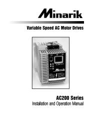
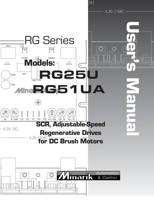
RG SeriesModels:RG25URG51UASCR, Adjustable-SpeedRegenerative Drivesfor DC Brush MotorsUser’s <strong>Manual</strong>
Copyright © 1998 by<strong>Minarik</strong> CorporationAll rights reserved. No part of this manual may be reproduced or transmitted inany form without written permission from <strong>Minarik</strong> Corporation. The informationand technical data in this manual are subject to change without notice. <strong>Minarik</strong>Corporation and its Divisions make no warranty of any kind with respect to thismaterial, including, but not limited to, the implied warranties of its merchantabilityand fitness for a given purpose. <strong>Minarik</strong> Corporation and its Divisions assume noresponsibility for any errors that may appear in this manual and make nocommitment to update or to keep current the information in this manual.Printed in the United States of America.
Safety Warnings• This symbol denotes an important safety tip or warning.Please read these sections carefully prior to performing any ofthe instructions contained in that section.• Have a qualified electrical maintenance technician install,adjust and service this equipment. Follow the NationalElectrical Code and all other applicable electrical and safetycodes, including the provisions of the Occupational Safetyand Health Act (OSHA), when installing equipment.• Reduce the chance of an electrical fire, shock, or explosion byproper grounding, over-current protection, thermal protection,and enclosure. Follow sound maintenance procedures.• It is possible for a drive to run at full speed as a result of acomponent failure. Please ensure that a master switch hasbeen placed in the AC line to stop the drive in an emergency.• This drive is isolated from earth ground. Circuit potentialsare at 115 VAC above earth ground. Avoid direct contact withthe printed circuit board or with circuit elements to prevent therisk of serious injury or fatality. Use a non-metallic screwdriverfor adjusting the calibration trimpots.
iiContentsSpecifications 1Dimensions 2Regenerative Drives 4Installation 6Mounting drives . . . . . . . . . . . . . . . . . . . . . . . . . . . . . . . . . . . . . . . . . . . . .6Line fusing . . . . . . . . . . . . . . . . . . . . . . . . . . . . . . . . . . . . . . . . . . . . . . . . .7Screw terminal block . . . . . . . . . . . . . . . . . . . . . . . . . . . . . . . . . . . . . . . . . .8Spade lugs . . . . . . . . . . . . . . . . . . . . . . . . . . . . . . . . . . . . . . . . . . . . . . . . .8Speed adjust potentiometer installation . . . . . . . . . . . . . . . . . . . . . . . . . . . .9RG25U Connections . . . . . . . . . . . . . . . . . . . . . . . . . . . . . . . . . . . . . . . . .10AC line and motor connections . . . . . . . . . . . . . . . . . . . . . . . . . . . . . .10Speed adjust potentiometer connections . . . . . . . . . . . . . . . . . . . . . .11RG51UA Connections . . . . . . . . . . . . . . . . . . . . . . . . . . . . . . . . . . . . . . . .12AC line, motor, and field connections . . . . . . . . . . . . . . . . . . . . . . . . .12Speed adjust potentiometer connections . . . . . . . . . . . . . . . . . . . . . .13Block Diagram . . . . . . . . . . . . . . . . . . . . . . . . . . . . . . . . . . . . . . . . . . . . . . . . .14Operation 16Before applying power . . . . . . . . . . . . . . . . . . . . . . . . . . . . . . . . . . . . . . .16Startup . . . . . . . . . . . . . . . . . . . . . . . . . . . . . . . . . . . . . . . . . . . . . . . . . . .16Line starting and line stopping . . . . . . . . . . . . . . . . . . . . . . . . . . . . . . . . . .16Automatic restart upon power restoration . . . . . . . . . . . . . . . . . . . . . . . . .17Regenerative deceleration (RG25U) . . . . . . . . . . . . . . . . . . . . . . . . . . . . .17Regenerative deceleration (RG51UA) . . . . . . . . . . . . . . . . . . . . . . . . . . . .18Warning . . . . . . . . . . . . . . . . . . . . . . . . . . . . . . . . . . . . . . . . . . . . . . . . . .18
iiiCalibration 19MAX SPD . . . . . . . . . . . . . . . . . . . . . . . . . . . . . . . . . . . . . . . . . . . . . . . . .19FWD TQ . . . . . . . . . . . . . . . . . . . . . . . . . . . . . . . . . . . . . . . . . . . . . . . . . .19REV TQ . . . . . . . . . . . . . . . . . . . . . . . . . . . . . . . . . . . . . . . . . . . . . . . . . .20IR COMP . . . . . . . . . . . . . . . . . . . . . . . . . . . . . . . . . . . . . . . . . . . . . . . . .20DB . . . . . . . . . . . . . . . . . . . . . . . . . . . . . . . . . . . . . . . . . . . . . . . . . . . . . .22Application Notes 23RG25U/RG51UA Connections to other <strong>Minarik</strong> devices . . . . . . . . . . . . . .23Optional speed adjust potentiometer connections . . . . . . . . . . . . . . . . . . .24Troubleshooting 29Replacement Parts 32CE Compliance for RG51UA 33Limited Warrantyinside back cover
IllustrationsFig Description Page1. RG25U Dimensions . . . . . . . . . . . . . . . . . . . . . . . . . . . . . . . . . . . . . . . . . .22. RG51UA Dimensions . . . . . . . . . . . . . . . . . . . . . . . . . . . . . . . . . . . . . . . . .33. Four-Quadrant Operation . . . . . . . . . . . . . . . . . . . . . . . . . . . . . . . . . . . . . .54. Screw Terminal Block . . . . . . . . . . . . . . . . . . . . . . . . . . . . . . . . . . . . . . . . .85. Speed Adjust Potentiometer Installation . . . . . . . . . . . . . . . . . . . . . . . . . . .96. RG25U AC Line and Motor Connections . . . . . . . . . . . . . . . . . . . . . . . . . .107a. RG25U Connection for Unidirectional Operation . . . . . . . . . . . . . . . . . . . .117b. RG25U Connection for Bidirectional Operation . . . . . . . . . . . . . . . . . . . . .118. RG51UA AC Line, Motor and Field Connections . . . . . . . . . . . . . . . . . . . .129a. RG51UA Connection for Unidirectional Operation . . . . . . . . . . . . . . . . . . .139b. RG51UA Connection for Bidirectional Operation . . . . . . . . . . . . . . . . . . . .1310. RG25U/RG51UA Series Block Diagram . . . . . . . . . . . . . . . . . . . . . . . . . .1411. RG25U Regenerative Deceleration Switch . . . . . . . . . . . . . . . . . . . . . . . .1712. RG51UA Regenerative Deceleration Switch . . . . . . . . . . . . . . . . . . . . . . .1813. Typical FWD TQ, REV TQ and IR COMP Settings . . . . . . . . . . . . . . . . . . .2114. Deadband Settings . . . . . . . . . . . . . . . . . . . . . . . . . . . . . . . . . . . . . . . . . .2215. RG25U/RG51UA Connection to Other <strong>Minarik</strong> Devices . . . . . . . . . . . . . . .2316. Forward-Reverse Switch . . . . . . . . . . . . . . . . . . . . . . . . . . . . . . . . . . . . . .2417. Forward-Stop-Reverse Switch . . . . . . . . . . . . . . . . . . . . . . . . . . . . . . . . . .2518. Independent Adjustable Speeds . . . . . . . . . . . . . . . . . . . . . . . . . . . . . . . .2619. Independent Forward and Reverse Speeds . . . . . . . . . . . . . . . . . . . . . . . .2720. Independent Forward and Reverse Speeds with FWD-STOP-REV Switch .28
vTablesFig Description Page1. Line Fusing for RG Series Drives . . . . . . . . . . . . . . . . . . . . . . . . . . . . . . . .72. Replacement Parts . . . . . . . . . . . . . . . . . . . . . . . . . . . . . . . . . . . . . . . . . .323. AC Line Filters . . . . . . . . . . . . . . . . . . . . . . . . . . . . . . . . . . . . . . . . . . . . .344. Armature Filters . . . . . . . . . . . . . . . . . . . . . . . . . . . . . . . . . . . . . . . . . . . .35
SpecificationsMax.ArmatureHP RangeCurrentwith 115 VACModel (Amps DC) AppliedRG25U 5.0 1/8–1/2RG51UA 5.0 1/8–1/2AC Line VoltagePeak Current LimitMaximum Armature Voltage Range at 115 VAC InputForm FactorAcceleration Time (with load)Deceleration Time (with load)Speed Adjust PotentiometerAnalog Input Voltage Range (isolated; S1 to S2)Input Impedance (S0 to S2) RG25URG51UA1115 VAC, ±10%, 50/60 Hz, single phase9 ADC60–75 VDC1.77 at base speed1 second1 second50KΩ0–10 VDC200KΩ100KΩLoad Regulation at Base Speed 3%Speed Range 50:1Weight - RG25UWeight - RG51UAAmbient Temperature RangeVibration.50 lb (227 grams).75 lb (340 grams)10°C–55°C0.5g max (0 – 50 Hz)0.1g max (above 50 Hz)RG51UA ONLYField Voltage (F1 to F2)Maximum Field Current100 VDC1 ADC
2DimensionsFigure 1. RG25U Dimensions
Dimensions3Figure 2. RG51UA Dimensions
4Regenerative DrivesMost non-regenerative, variable speed, DC drives controlcurrent flow to a motor in one direction. The direction ofcurrent flow is the same direction as the motor rotation.Non-regenerative drives operate in Quadrant 1, and also inQuadrant 3 if the drive is reversible (Figure 3). Motors muststop before reversing direction. Unless dynamic braking isused, non-regenerative drives cannot oppose an overhaulingload, and cannot decelerate a load faster than coasting to alower speed.Regenerative drives operate in two additional quadrants:Quadrant 2 and Quadrant 4. In these quadrants, motor torqueis in the opposite direction of motor rotation.Regenerative drives can reverse a motor without contactors,switches, brake resistors, and inhibit plugs. They can alsocontrol an overhauling load and decelerate a load faster than itwould take to coast to a lower speed.The RG25U and the RG51UA are regenerative drives. Theyare uncased chassis model drives and designed to be installedin original equipment. The drives are the same electrically.The physical layout and size of these drives are different (seeDimensions section). The RG51UA includes a field supply forshunt wound motors.The RG25U and the RG51UA are half wave rectified DCregenerative drives. Therefore the maximum armature voltage
Regenerative Drives5of these drives is 75 VDC. This means that a 90 VDC motorwill only run at about 83% of rated nameplate speed.The form factor of the RG25U and the RG51UA is 1.77. Thiswill cause a higher-than-normal heating in the motorarmature. To prevent a shorter-than-normal motor life,<strong>Minarik</strong> recommends that the horsepower rating of the motorfor a given application be at least 50% greater than therequired horsepower.Figure 3. Four Quadrant Operation
6InstallationASSUMPTIONS: <strong>Minarik</strong> drives supply motor voltage fromA1 (or A+) and A2 (or A–) terminals. It is assumedthroughout this manual that, when A1 (or A+) is positive withrespect to A2 (or A–), the motor will rotate clockwise (CW)while looking at the output shaft protruding from the front ofthe motor. If this is opposite of the desired rotation, simplyreverse the wiring of A1 (or A+) and A2 (or A–) with eachother.Mounting drivesDrive components are sensitive to electrostatic fields. Avoidcontact with the circuit board directly. Hold the drive by thechassis only.Protect the drive from dirt, moisture, and accidental contact.Provide sufficient room for access to the terminal block andcalibration trimpots.Mount the drive away from other heat sources. Operatethe drive within the specified ambient operating temperaturerange.Prevent loose connections by avoiding excessive vibrationof the drive.
Installation7Mount the drive with its board in either a horizontal orvertical plane. The RG25U has six 0.188 inch (4.8 mm) wideslots in the chassis that accept #8 pan head screws. Fasteneither the large base or the narrow flange of the chassis to thesubplate. The RG51UA has four 0.188 inch (4.8mm) wideslots in the base of the chassis that accept #8 pan head screws.The chassis must be earth grounded for noise suppression. Toground the RG51UA chassis, connect earth ground to theGND terminal on the seven position terminal block.To ground the RG25U use a star washer beneath the head of atleast one of the mounting screws to penetrate the anodizedchassis surface and to reach bare metal.Line fusingThe National Electrical Code requires the installation of acircuit breaker or fuse on the incoming AC line voltage. Use acircuit breaker or fast acting fuse rated for 8 amps or less.With an 115VAC line voltage fuse the hot leg of the AC linethat connects to L1 and leave L2 unfused. Use 250VAC fuses.See Table 1 for recommended line fuse sizes.Table 1. Recommended Line Fuse Sizes90 VDC Maximum Armature FuseMotor HP Current Rating1/8 1.5 31/4 2.6 51/3 3.5 81/2 5.0 8
8 InstallationScrew terminal blockConnections to RG51UA drives are made to a screw terminalblock (Figure 4). Using a screwdriver, turn the terminal blockscrew counter-clockwise to open the wire clamp. Turn theterminal block screw clockwise to clamp the wire.Terminal Block ScrewWire ClampFigure 4. Screw Terminal BlockSpade lugsConnections to the RG25U are made to .25 inch (.6 mm)spade lugs on the drive.
Installation9Speed adjust potentiometer installationInstall the circular insulating disk between the panel and the50K ohm speed adjust potentiometer. Mount the speed adjustpotentiometer through a 0.38 inch (0.96 cm) hole with thehardware provided (Figure 5). Twist the speed adjustpotentiometer wire to avoid drawing unwanted electricalnoise. If potentiometer leads are longer than 18 inches(46 cm.), use shielded cable. WarningBe sure that the potentiometer tabs do not make contact withthe potentiometer enclosure. Grounding the input will causedamage to the drive.Figure 5. Speed Adjust Potentiometer
10 InstallationRG25U ConnectionsAC line and motor connectionsUse 14 AWG or 16 AWG standard wire for connecting theline and the armature. When connecting the line, standardsrequire installation of a fuse. See page 7 for the details on fusesizing.The RG25UA does not have a field output.Figure 6. RG25U AC Line and Motor Connections
Installation11Speed adjust potentiometer connectionsThe motor can operate in one direction (unidirectional) or intwo directions (bidirectional) depending on how the speedadjust potentiometer is connected to the drive.Connect the speed adjust potentiometer as shown inFigure 7(a) for speed control in one direction.Connect the speed adjust potentiometer as shown inFigure 7(b) for speed control in two directions. The motordoes not rotate when the wiper is in the center position.Turning the wiper CW from the center position causes themotor to rotate in one direction, while turning the wiper CCWfrom the center position causes the motor to rotate in theopposite direction.Refer to the Application Notes section (page 23) for additionalspeed adjust potentiometer connections.50K ohmSpeed Adjust PotentiometerFigure 7a.Unidirectional Operation50K ohmSpeed Adjust PotentiometerFigure 7b.Bidirectional Operation
12 InstallationRG51UA ConnectionsAC line, motor and field connectionsThe motor and AC line connections to the RG51UA are madeto the 7 screw terminal block. Use 14 AWG or 16 AWGstandard wire for connecting the line and the armature. Stripthe wire insulation 0.25 inches (6 mm).The field output is for shunt wound motors only.Do not make any connections to F1 and F2 when using apermanent magnet motor.The field output connection for the RG51UA is made to the7 screw terminal block. Use 16 or 18 AWG wire to connectthe field output to a shunt wound motor. See Figure 8 forRG51UA connections.Figure 8. RG51UA AC Line, Motor and Field Connections
Speed adjust potentiometer connectionsInstallationThe motor can operate in one direction (unidirectional) or intwo directions (bidirectional) depending on how the speedadjust potentiometer is connected to the drive. Speed adjustpotentiometer connections are made to the 5 screw terminalblock.Connect the speed adjust potentiometer as shown inFigure 9(a) for speed control in one direction.Connect the speed adjust potentiometer as shown inFigure 9(b) for speed control in two directions. The motordoes not rotate when the wiper is in the center position.Turning the wiper CW from the center position causes themotor to rotate in one direction, while turning the wiper CCWfrom the center position causes the motor to rotate in theopposite direction.Refer to the Application Notes section for additional speedadjust potentiometer connections.13Figure 9a.Unidirectional OperationFigure 9b.Bidirectional Operation
14Block DiagramFigure 10. RG25U/RG51UA Series Block Diagram
Block Diagram15NOTES:1. RG25U does not have a field output.2. RG25U has RB terminal.3. RG51UA has TO terminal.4. RG51UA has an earth ground terminal.
16OperationBefore applying power1. Check connections before applying AC line voltage to thedrive.2. Check that no conductive material is present on the printedcircuit board.Startup1. Set the speed adjust potentiometer for zero speed. This maybe the center position of the potentiometer if the drive iswired for bidirectional operation or fully counterclockwiseif the drive is wired for unidirectional operation.2. Apply AC line voltage.3. Slowly advance the speed adjust potentiometer clockwise(CW). The motor slowly accelerates as the potentiometer isturned CW. Continue until the desired speed is reached. Ifthe potentiometer is wired for bidirectional control, advancethe potentiometer in either direction off center and themotor will accelerate as the potentiometer is turned.4. Remove AC line voltage from the drive to coast the motorto a stop.Line starting and line stoppingLine starting and line stopping (applying and removing ACline voltage) is not recommended with regenerative drives,
Operation17except in emergency conditions: line starting and stoppingdefeats the 4-quadrant control. When AC line voltage isapplied to the drive, the motor accelerates to the speed set bythe speed adjust potentiometer. When AC line voltage isremoved, the motor coasts to a stop.Automatic restart upon power restorationAll drives automatically run to set speed when power isapplied. Wiring a latching relay into the AC line is one wayto prevent automatic restarting following a power outage.Regenerative deceleration (RG25U)Short terminals S0 and RB to regeneratively decelerate amotor to a stop (Figure 11). Because there is no decelerationadjustment on this drive, the speed at which the decelerationof the motor takes place will be completely dependent uponload inertia, friction, and the settings of the FWD TQ andREV TQ trimpots. This is the fastest stopping action available.Figure 11. RG25U Regenerative DecelerationSwitch Connection
18 OperationRegenerative deceleration (R51UA)Short terminals S0 and T0 to regeneratively decelerate themotor to a stop (Figure 12). Because there is no decelerationadjustment on this drive, the speed at which the decelerationof the motor takes place will be completely dependent uponload inertia, friction and the settings of the FWD TQ and REVTQ trimpots. This is the fastest stopping action available.Figure 12. RG51UA Regenerative DecelerationSwitch Connection WarningFor frequent starts and stops, use regenerative deceleration(shorting RB and S0 on RG25U, or shorting S0 and T0 onRG51UA). Do not use of this method for emergencystopping. They may not stop a drive that is malfunctioning.Removing AC line power (both L1 and L2) is the onlyacceptable method for emergency stopping.Frequent regenerative deceleration, regenerative braking,produces high torque. This may cause damage to motors,especially gearmotors that are not properly sized for theapplication.
19CalibrationEach drive is factory calibrated to its maximumhorsepower rating. Readjust the calibration trimpotsettings to accommodate lower horsepower motors.All adjustments increase with CW rotation, and decrease withCCW rotation. Use a non-metallic screwdriver for calibration.Each trimpot is identified on the printed circuit board.MAX SPDThe MAX SPD setting determines the maximum motor speedwhen the speed adjust potentiometer is turned full CW. It isfactory set for maximum rated motor speed.To calibrate, set the speed adjust potentiometer full CW.Adjust the MAX SPD trimpot until the motor turns at thedesired maximum speed.FWD TQThe FWD TQ setting determines the maximum torque foraccelerating and driving the motor in the forward direction. Italso sets the maximum torque for decelerating the motor in thereverse direction. FWD TQ is factory set at 120% of ratedmotor current.
20 CalibrationIf the time it takes to accelerate a load is too long due tothe forward torque setting, increase the forward torque settingto 130% of rated motor current. The decision to change theforward torque setting must be made after considering thegearbox and drivetrain ratings, duty cycle, and motorcharacteristics. See Figure 13 for typical FWD TQ settings.REV TQThe REV TQ setting determines the maximum torque foraccelerating and driving the motor in the reverse direction. Italso sets the maximum torque for decelerating in the forwarddirection. REV TQ is factory set at 120% of rated motorcurrent.If the time it takes to accelerate a load is too long due tothe reverse torque setting, increase the reverse torque settingto 130% of rated motor current. The decision to change thereverse torque setting must be made after considering thegearbox and drivetrain ratings, duty cycle, and motorcharacteristics. See Figure 13 for typical REV TQ settings.IR COMPThe IR COMP setting determines the degree to which motorspeed is held constant as the motor load changes. It is factoryset for optimum motor regulation.Recalibrate the IR COMP setting when using a lowerhorsepower motor. See Figure 13 for typical IR COMP
Calibration21settings, or recalibrate using the following procedure:If the motor does not maintain set speed as the load changes,gradually rotate the IR COMP trimpot CW. If the motoroscillates (overcompensation), the IR COMP trimpot may beset too high (CW). Turn the IR COMP trimpot CCW until themotor load stabilizes.RG25URG51UAFigure 13. Typical FWD TQ, REV TQ, and IR COMP Settings(actual settings may vary with each application)
22CalibrationDBThe deadband trimmer potentiometer determines the timethat will elapse between the application of current in onedirection before current is applied in the opposite direction.The deadband trimmer potentiometer affects theresistance that a motor has to changes in shaft position atzero speed. It does this by applying AC voltage to the motorarmature.Deadband is factory calibrated to approximately the3 o’clock position for 60 Hz AC line operation. Recalibratethe deadband to the 9 o’clock position for 50 Hz AC lineoperation. See Figure 14 for recommended deadband settings.Figure 14. Deadband Settings
Application Notes23RG25U/RG51UA Connections to other <strong>Minarik</strong> devicesFigure 15. RG25U/RG51UA Connection toDLC100(DLC200), DLC300(DLC400), and PCM4
24 Application NotesOptional speed adjust potentiometer connectionsUse a single pole, two position switch with a single speedadjust potentiometer to plug reverse the motor (Figure 16).The MIN SPD setting is in effect for either direction.RG25URG51UAFigure 16. Forward-Reverse Switch
Application Notes25Use a single pole, three position switch with a single speedadjust potentiometer to stop a motor between reversals(Figure 17). Set the switch to the center position to deceleratethe motor to a stop.RG25URG51UAFigure 17. Forward-Stop-Reverse Switch
26 Application NotesConnect two speed adjust potentiometers with a single poletwo position switch to select between two independent speedsshown in the forward direction (Figure 18). The speed adjustpotentiometers can be mounted at two separate operatingstations.RG25URG51UAFigure 18. Independent Adjustable SpeedsForward Direction
Application Notes27Connect two speed adjust potentiometers as shown inFigure 19 to select between independent forward andreverse speeds.RG25URG51UAFigure 19. Independent Forward and Reverse Speeds
28 Application NotesUse a single pole, three position switch to stop the motorwhen the switch is in the center position (Figure 20).RG25URG51UAFigure 20. Independent Forward and Reverse Speeds with aForward-Stop-Reverse Switch
29Troubleshooting WarningDangerous voltages exist on the drive when it is powered.When possible, disconnect the AC line voltage from the drivewhile troubleshooting. Be alert. High voltages can causeserious or fatal injury.Before troubleshootingPerform the following steps before starting any procedure inthis section:• Disconnect AC line voltage from the drive.• Check the drive closely for damaged components.• Check that no conductive or other foreign material hasbecome lodged on the printed circuit board.• Verify that every connection is correct and in goodcondition.• Verify that there are no short circuits or groundedconnections.• Check that the drive’s rated armature and field outputs areconsistent with the motor ratings.
30 TroubleshootingMotor does not run1. Check for blown fuses or tripped circuit breaker.2. Verify that the speed adjust potentiometer is not set to zerospeed position.3. Verify that the drive is receiving AC line voltage.4. Check that the drive is not in current limit. It may benecessary to increase the FWD TQ and REV TQ setting if itis set to a value lower than the current rating of the motor.Fuses or circuit breaker blows1. Check all wiring for shorts, grounds, or misconnections.2. Check that the drive is configured to match the motorrating.3. Check that the motor is not jammed or restricted frommovement.Motor runs too fast at the maximum speed setting1. Check that the MAX SPD setting is not set too high.2. Check that the field output connections (RG51UA only) aresecure if you are using a shunt wound motor.Motor will not stop when the speed adjust potentiometer isset to zero speedTurn the deadband trimpot CCW until the motor stops.
Troubleshooting31Motor runs in the opposite direction and speed adjustpotentiometer is connected for unidirectional operation1. Remove AC line voltage.2. Reverse connections to the motor armature.Motor slows under load1. Check that the drive has been correctly calibrated for themotor.2. Check that the motor is not overloaded.3. Readjust the IR COMP slightly CW until motor runs atproper speed.Motor is unstable under loadReadjust the IR COMP setting slightly CCW until motorspeed is stabilized.Motor only runs at full speed1. Check if the speed adjust potentiometer is open.2. Check if the connections to for the speed potentiometer areopen.For additional assistance, contact your local <strong>Minarik</strong> ®Distributor, or the factory direct: phone (818) 502-1528; fax(818) 502-0716.
32Replacement PartsReplacement parts are available form <strong>Minarik</strong> Corporation and itsdistributors for this drive series.Table 2. Replacement PartsModel No. Symbol Description <strong>Minarik</strong> ® P/NRG51UA R501 0.05Ω, 7 W Resistor 032-0031SCR501-502 800 V, 25 A SCR 072-0042T505 Transformer 230-000450KΩ Potentiometer Kit 202-0005Chassis 223-01887 Screw Terminal Block 160-00195 Screw Terminal Block 160-0060Model No. Symbol Description <strong>Minarik</strong> ® P/NRG25U R501 0.05Ω, 10W Resistor 032-0132SCR501-502 800 V, 25 A SCR 072-0042T505 Transformer 230-000450KΩ Potentiometer Kit 202-0067Chassis 222-0079
33Certificate of Compliance<strong>Minarik</strong> Corporation hereby certifies that its RG51UA drive has beenapproved to bear the “CE” mark provided the conditions of approvalhave been met by the end user.The RG51UA has been tested to the following test specifications:EN55011:1991 (emissions), andEN50082-1:1992 (immunity)Compliance allows the RG51UA to bear the CE mark.The end user, as described herein, falls into one of two categories:1. The Consumer will deploy a stand-alone unit as an integral,yet external, portion of the machine being operated.2. The Original Equipment Manufacturer (OEM) will implementthe product as a component of the machine beingmanufactured.
34 Certificate of ComplianceAC Line FiltersIn addition to EMI/RFI safeguards inherent in the RG51UA design,external filtering is required.<strong>Minarik</strong> requires the Corcom ® AC line filters listed in Table 3. Usemodel 5VR1 with drives rated for 3 ADC or below, and model 20VV1with drives rated for 10 ADC or below.Table 3. AC Line FiltersCorcom ® Model Number 5VR1 20VV1Rated Current 5 A 20 AInductance 1.032 mH 0.88 mHCapacitanceLine to Line 0.303 mF 0.303 mFLine to Ground 0.011 mF 0.011 mFDischarge Resistor 680 KW 680 KWWire the AC line filter within 0.25 meters of the drive. Theground connection from the filter must be wired to solidearth ground (resistance less than 500 ohms), not machineground. This is very important!If the end-user is using a CE-approved motor, the correct filter fromTable 3 is all that is necessary to meet the EMC directives listedherein.
Certificate of Compliance35Armature FiltersIf the end-user is not using a CE-approved motor, a second filter on thearmature must be deployed. See Table 4 for recommended armaturefilters. Use model CE04RG with drives rated for 3 ADC or below, andmodel CE10RG with drives rated for 10 ADC or below.Table 4. Armature Filters<strong>Minarik</strong> ® Model Number CE04RG CE10RGRated Current 4 A 10 AInductance1200 mHCapacitance (C1 and C2)0.1 mF @ 400W VDCDischarge Resistor680KWWire the armature filter to the DC output of the drive, asclose to the drive as possible. The ground connection fromthe filter must be wired to solid earth ground (resistanceless than 500 ohms); not machine ground. This is veryimportant!The end user must use the filtration listed in this addendum to complywith CE. The OEM may choose to provide alternative filtering thatencompasses the <strong>Minarik</strong> drive and other electronics within the samepanel.The OEM has this liberty because CE is a machinery directive.
36 Certificate of ComplianceWhether or not every component in the OEM’s machinery meets CE,the OEM must still submit his machine for CE approval. Thus, nocomponent must necessarily meet CE within the machine, as long asthe OEM takes the necessary steps to guarantee the machine does meetCE. By the same token, even if every component in the OEM’smachine does meet CE, the machine will not necessarily meet CE as amachine.Using CE-approved wiring practices (like proper shielding) and thefilters should assure the drive will meet EN55014 (1993 emissionsstandard) and EN50082-1 (1992 immunity standard).
Notes37
38Notes
Limited WarrantyA. Warranty - <strong>Minarik</strong> Corporation (referred to as “the Corporation”) warrants that its products willbe free from defects in workmanship and material for two (2) years or 6,000 hours, whichevercomes first, from date of shipment thereof. Within this warranty period, the Corporation will repairor replace such products that are: (1) returned to <strong>Minarik</strong> Corporation, 901 East ThompsonAvenue, Glendale, CA 91201-2011 USA; and, (2) determined by the Corporation to be defective.This warranty shall not apply to any product that has been subject to misuse, negligence, oraccident; or misapplied; or repaired by unauthorized persons; or improperly installed. TheCorporation is not responsible for removal, installation, or any other incidental expenses incurredin shipping the product to and from the repair point.B. Disclaimer - The provisions of Paragraph A are the Corporation’s sole obligation and excludeall other warranties of merchantability for use, express or implied. The Corporation furtherdisclaims any responsibility whatsoever to the customer or to any other person for injury to theperson or damage or loss of property of value caused by any product that has been subject tomisuse, negligence, or accident, or misapplied or modified by unauthorized persons or improperlyinstalled.C. Limitations of Liability - In the event of any claim for breech of any of the Corporation’sobligations, whether express or implied, and particularly of any other claim or breech of warrantycontained in Paragraph A, or of any other warranties, express or implied, or claim of liability thatmight, despite Paragraph B, be decided against the Corporation by lawful authority, theCorporation shall under no circumstances be liable for any consequential damages, losses, orexpense arising in connection with the use of, or inability to use, the Corporation’s product for anypurpose whatsoever.An adjustment made under warranty does not void the warranty, nor does it imply an extension ofthe original two (2) year or 6,000 hour warranty period. Products serviced and/or parts replaced ona no-charge basis during the warranty period carry the unexpired portion of the original warrantyonly.If for any reason any of the foregoing provisions shall be ineffective, the Corporation’s liability fordamages arising out of its manufacture or sale of equipment, or use thereof, whether such liabilityis based on warranty, contract, negligence, strict liability in tort, or otherwise, shall not in any eventexceed the full purchase price of such equipment.Any action against the Corporation based upon any liability or obligation arising hereunder orunder any law applicable to the sale of equipment or the use thereof, must be commenced withinone year after the cause of such action arises.
Other drives from <strong>Minarik</strong> Corporation:XP Series MM30000 Series MM03-PCMMM23000 Series901 East Thompson AvenueGlendale, California 91201-2011Phone: (818) 502-1528Fax: (818) 502-0716www.minarikcorp.comDocument Number 250-0226, Revision 2Printed in the U.S.A – 1/98North America $10.00, Outside North America $11.00