

EMI Failure Analysis Techniques - IEEE EMC Society
EMI Failure Analysis Techniques - IEEE EMC Society
EMI Failure Analysis Techniques - IEEE EMC Society

You also want an ePaper? Increase the reach of your titles
YUMPU automatically turns print PDFs into web optimized ePapers that Google loves.
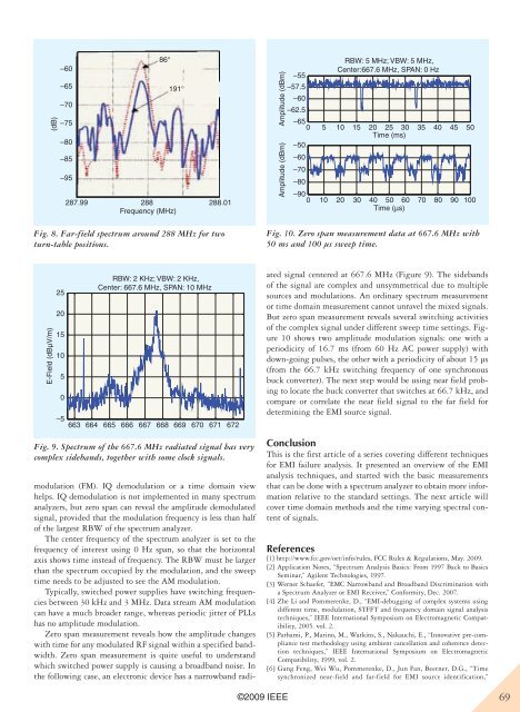
(dB)–60–65–70–75–80–85–9586°191°287.99 288 288.01Frequency (MHz)Fig. 8. Far-field spectrum around 288 MHz for twoturn-table positions.Amplitude (dBm)Amplitude (dBm)–55RBW: 5 MHz; VBW: 5 MHz,Center:667.6 MHz, SPAN: 0 Hz–57.5–60–62.5–650 5 10 15 20 25 30 35 40 45 50Time (ms)–50–60–70–80–900 10 20 30 40 50 60 70 80 90 100Time (µs)Fig. 10. Zero span measurement data at 667.6 MHz with50 ms and 100 µs sweep time.E-Field (dBµV/m)2520151050–5RBW: 2 KHz; VBW: 2 KHz,Center: 667.6 MHz, SPAN: 10 MHz663 664 665 666 667 668 669 670 671 672modulation (FM). IQ demodulation or a time domain viewhelps. IQ demodulation is not implemented in many spectrumanalyzers, but zero span can reveal the amplitude demodulatedsignal, provided that the modulation frequency is less than halfof the largest RBW of the spectrum analyzer.The center frequency of the spectrum analyzer is set to thefrequency of interest using 0 Hz span, so that the horizontalaxis shows time instead of frequency. The RBW must be largerthan the spectrum occupied by the modulation, and the sweeptime needs to be adjusted to see the AM modulation.Typically, switched power supplies have switching frequenciesbetween 30 kHz and 3 MHz. Data stream AM modulationcan have a much broader range, whereas periodic jitter of PLLshas no amplitude modulation.Zero span measurement reveals how the amplitude changeswith time for any modulated RF signal within a specified bandwidth.Zero span measurement is quite useful to understandwhich switched power supply is causing a broadband noise. Inthe following case, an electronic device has a narrowband radiatedsignal centered at 667.6 MHz (Figure 9). The sidebandsof the signal are complex and unsymmetrical due to multiplesources and modulations. An ordinary spectrum measurementor time domain measurement cannot unravel the mixed signals.But zero span measurement reveals several switching activitiesof the complex signal under different sweep time settings. Figure10 shows two amplitude modulation signals: one with aperiodicity of 16.7 ms (from 60 Hz AC power supply) withdown-going pulses, the other with a periodicity of about 15 µs(from the 66.7 kHz switching frequency of one synchronousbuck converter). The next step would be using near field probingto locate the buck converter that switches at 66.7 kHz, andcompare or correlate the near field signal to the far field fordetermining the <strong>EMI</strong> source signal.Fig. 9. Spectrum of the 667.6 MHz radiated signal has verycomplex sidebands, together with some clock signals.ConclusionThis is the first article of a series covering different techniquesfor <strong>EMI</strong> failure analysis. It presented an overview of the <strong>EMI</strong>analysis techniques, and started with the basic measurementsthat can be done with a spectrum analyzer to obtain more informationrelative to the standard settings. The next article willcover time domain methods and the time varying spectral contentof signals.References[1] http://www.fcc.gov/oet/info/rules, FCC Rules & Regulations, May. 2009.[2] Application Notes, “Spectrum <strong>Analysis</strong> Basics: From 1997 Back to BasicsSeminar,” Agilent Technologies, 1997.[3] Werner Schaefer, “<strong>EMC</strong> Narrowband and Broadband Discrimination witha Spectrum Analyzer or <strong>EMI</strong> Receiver,” Conformity, Dec. 2007.[4] Zhe Li and Pommerenke, D., “<strong>EMI</strong>-debugging of complex systems usingdifferent time, modulation, STFFT and frequency domain signal analysistechniques,” <strong>IEEE</strong> International Symposium on Electromagnetic Compatibility,2005. vol. 2.[5] Parhami, P., Marino, M., Watkins, S., Nakauchi, E., “Innovative pre-compliancetest methodology using ambient cancellation and coherence detectiontechniques,” <strong>IEEE</strong> International Symposium on ElectromagneticCompatibility, 1999, vol. 2.[6] Gang Feng, Wei Wu, Pommerenke, D., Jun Fan, Beetner, D.G., “Timesynchronized near-field and far-field for <strong>EMI</strong> source identification,”©2009 <strong>IEEE</strong>69


