Chapter D Finite State Machines
Chapter D Finite State Machines
Chapter D Finite State Machines
- No tags were found...

Create successful ePaper yourself
Turn your PDF publications into a flip-book with our unique Google optimized e-Paper software.
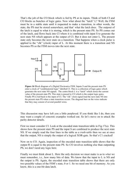
That’s the job of the CO block which is fed by PS at its inputs. Think of both CI andCO blocks as bunches of logic gates. Now what about the “latch” L? Well, the FSMmust be in a stable state until it requested to make a transition, in other words, thestate, the PS mut be stored somewhere, and that’ what the latch does. The outpout ofthe latch is equal to what it is storing, which is the present state PS. So PS comes outof the latch, and flows back into CI where it is combined with input S to generate thenext state NS which appears at the output of CI. But it does not enter L. The presentstate only becomes the next state on a transition. That happens when a clock pulse isapplied to the “clk” (clock) input of L. At this moment there is a transition and NSbecomes PS so the FSM moves into the next state.Input S/PSCINS/LCO/ /Output R/clkFigure 16 Block diagram of a Digital Electronics FSM. Inputs S and the present state PSenter a clock of “combinatorial logic” labelled CI. This is a collection of logic gates whichgenerates the next state NS signals. The centre block L is a “latch” which stores the currentvalue of the present state PS. This state is passed to CO which is the output logic gates.Finally PS is fed-back to the input of CI. The “clk” clock signal load the next state NS intothe present state PS when a state transition occurs. The diagonal bars on the wires indicatethat they may consist of several parallel wires.This discussion may have left you a little perplexed. If you think like I do, then youmay want a couple of concrete examples worked out. So let’s move on to attack theparity detector details.First we must consider CI. Look at the encoded state transition table in Fig.17(a). Thisshows how the present state PS and the input S are combined to produce the next stateNS. If we simply read the four lines in the table as a truth-table then we see at oncethat the output, NS is simply the output of a logical XOR-gate. So that’s C1 cracked!Now on to CO. Again, inspection of the encoded state transition table shows that theoutput R is equal to the present state PS. So CO involves nothing else than outputtingPS, we don’t need any logic here.Finally we must think about L. Here the only decision we must make is as to what wemust remember, i.e., how many bits of data. We know that the input to L is NS andthe output is PS. Again, the encoded state transition table shows that there are onlytwo possible values of the FSM’s state, 0 or 1. So we need one bit of memory. As youknow, this is a one-bit data latch.