Chapter D Finite State Machines
Chapter D Finite State Machines
Chapter D Finite State Machines
- No tags were found...

You also want an ePaper? Increase the reach of your titles
YUMPU automatically turns print PDFs into web optimized ePapers that Google loves.
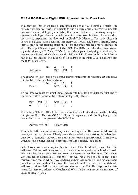
D.16 A ROM-Based Digital FSM Approach to the Door LockIn a previous chapter we took a hard-nosed look at digital electronic circuits. Oneprinciple we saw was that it is possible to use a programmable memory to simulateany combination of logic gates. Also, that there exist chips containing arrays ofprogrammable logic elem ents w hich can effect these logic functions. Here we shallsee how to implement the door-lock in Read-Only-Memory. The basic circuit isshown in Fig.21(a) which contains four elements, a ROM, and three D-latches. Theselatches provide the latching function “L” for the three bits required to encode thestates Qn, input S and output R of the FSM. The ROM provides the combinatoriallogic functionality (“CI” and “CO”). At each clock pulse instigating a transition, thepresent state PS exits the latch as two bits, PS2 and PS1. These are fed to the ROM aspart of a 3-bit address. The third bit of the address is the input S. So the address intothe ROM has this formBit 4 2 1Address = PS2 PS1 SThe data which is selected by this input address represents the next state NS and flowsinto the latch. The data has this formBit 4 2 1Data = NS2NS1 RTo see how we must construct these address-data bits, let’s consider the first line ofthe encoded state transition table shown in Fig.15(b). This isPS2 PS1 S NS2 NS1 R0 1 0 1 0 0The address (PS2 PS1 S) is 010. Since we must have a 4-bit address, we add a leading0 to give us 0010. The data (NS2 NS1 R) is 100. Again we add a leading 0 to give thedata 0100. So we have generatedthe ROM lineAddress = 0010 Data = 0100This is the fifth line in the memory shown in Fig.21(b). The entire ROM contentswere generated in this way. Clearly, once the encoded state transition table has beenbuilt for a particular problem, then the ROM-based implementation is simple togenerate, much easier than an implementation using discrete logic gates.A final comment concerning the first two lines of the ROM address and data. Theadd resses 000 and 001 have no correspondence in the symbolic table (they wouldhave encoded state “Q0”). But we started our symbolic labelling with “Q1” whichwas encoded as addresses 010 and 011. This was not a wise choice, in fact it is amistake, since the ROM has two locations without any meaning, and the electroniccircuit will reference these locations. To recover from this mistake, we put data intoaddresses 000 and 001 to get us into our starting state 010. This explains the datavalues for these two addresses. Conclusion? Well, it’s best to start our enumeration ofstatesat zero, ie “Q0”.