Chapter D Finite State Machines
Chapter D Finite State Machines
Chapter D Finite State Machines
- No tags were found...

You also want an ePaper? Increase the reach of your titles
YUMPU automatically turns print PDFs into web optimized ePapers that Google loves.
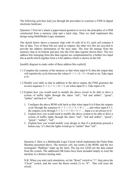
The following activities lead you through the procedure to construct a FSM in digitalelectronic hardware.Question 1 First let’s attack a paper-based question to review the principles of a FSMconstructed from a memory chip and a latch chip. Then we shall implement thisdesign using MultiMedia Logic simulator.The sketch below shows a memory chip with 16 cells (0 to F), each cell contains 4bits of data. Two of these bits are used as outputs, the other two bits are recycled toprovide the address information of the next state. The four bit emerge from thememory chip at its bottom and pass into the 4-bit data register shown there. The twoaddress bits emerging from this data register are complemented by a further two inputbits a and b which together form a 4-bit address which is shown on the left.[modify diagram to make order of these address bits explicit]1.1 Complete the contents of the memory so that when input b=0, then the output datawill repetitively cycle between the values 0 -> 1 ->2 ->3 ->0 and so on. Take inputa=0;1.2 Modify your table so that in addition to the above output, the FSM generates thereverse sequence 3 -> 2 -> 1 -> 0 -> 3, etc when input b=1. Take input a=0;1.3 Explain how you would need to modify the above circuit to be able to drive asystem of traffic lights through the states “red”, “red and amber”, “green”,“amber” and back to “red”.1. Configure the above ROM with latch so that when input b is 0 then the outputscycle through the sequence 0 -> 1 -> 2 -> 3 -> 0 -> …, and when input b I 1,the outputs cycle through 3 -> 2 -> 1 -> 0 -> 3 -> … Input a is set always to 0.2. Explain how you would need to modify the above system to be able to drive asystem of traffic lights through the states “red”, “red and amber”, “green”,“green”, “amber”, “red”.3. Explain how you would modify your design so that if a pedestrian pressed abutton (say “a”) then the lights would go to “amber” then “red”.Question 2. Here is a Multimedia Logic Circuit which implements the <strong>Finite</strong> <strong>State</strong>Machine presented above. The memory cell, top centre is the ROM, and the tworectangular “flipflops” make up the latch. The top two LEDs are the data outputfrom the system. The additional OR-Gates have been included simply to reset themachine to a distinct starting state.N.B. When you start each simulation, set the “Reset” switch to “1”, then press the“Clock” switch, and the reset the Reset switch (!) to “0”. This will reset thecircuit.