Chapter D Finite State Machines
Chapter D Finite State Machines
Chapter D Finite State Machines
- No tags were found...

You also want an ePaper? Increase the reach of your titles
YUMPU automatically turns print PDFs into web optimized ePapers that Google loves.
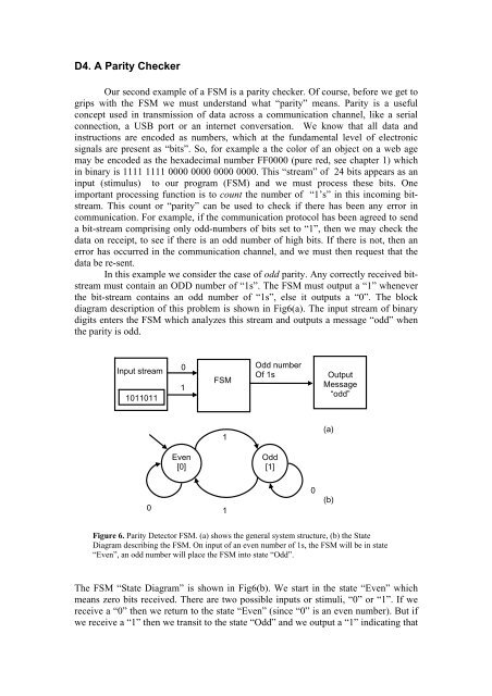
D4. A Parity CheckerOur second example of a FSM is a parity checker. Of course, before we get togrips with the FSM we must understand what “parity” means. Parity is a usefulconcept used in transmission of data across a communication channel, like a serialconnection, a USB port or an internet conversation. We know that all data andinstructions are encoded as numbers, which at the fundamental level of electronicsignals are present as “bits”. So, for example a the color of an object on a web agemay be encoded as the hexadecimal number FF0000 (pure red, see chapter 1) whichin binary is 1111 1111 0000 0000 0000 0000. This “stream” of 24 bits appears as aninput (stimulus) to our program (FSM) and we must process these bits. Oneimportant processing function is to count the number of “1’s” in this incoming bitstream.This count or “parity” can be used to check if there has been any error incommunication. For example, if the communication protocol has been agreed to senda bit-stream comprising only odd-numbers of bits set to “1”, then we may check thedata on receipt, to see if there is an odd number of high bits. If there is not, then anerror has occurred in the communication channel, and we must then request that thedata be re-sent.In this example we consider the case of odd parity. Any correctly received bitstreammust contain an ODD number of “1s”. The FSM must output a “1” wheneverthe bit-stream contains an odd number of “1s”, else it outputs a “0”. The blockdiagram description of this problem is shown in Fig6(a). The input stream of binarydigits enters the FSM which analyzes this stream and outputs a message “odd” whenthe parity is odd.Input stream10110110 Odd numberOf 1sFSM1OutputMessage“odd”1(a)Even[0]Odd[1]010(b)Figure 6. Parity Detector FSM. (a) shows the general system structure, (b) the <strong>State</strong>Diagram describing the FSM. On input of an even number of 1s, the FSM will be in state“Even”, an odd number will place the FSM into state “Odd”.The FSM “<strong>State</strong> Diagram” is shown in Fig6(b). We start in the state “Even” whichmeans zero bits received. There are two possible inputs or stimuli, “0” or “1”. If wereceive a “0” then we return to the state “Even” (since “0” is an even number). But ifwe receive a “1” then we transit to the state “Odd” and we output a “1” indicating that