Print Fluent Newsletter
Print Fluent Newsletter
Print Fluent Newsletter

You also want an ePaper? Increase the reach of your titles
YUMPU automatically turns print PDFs into web optimized ePapers that Google loves.
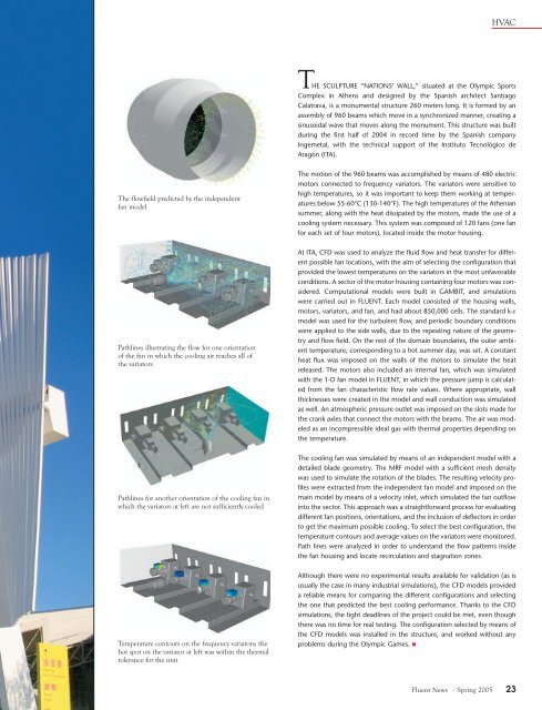
HVACTHE SCULPTURE “NATIONS’ WALL,” situated at the Olympic SportsComplex in Athens and designed by the Spanish architect SantiagoCalatrava, is a monumental structure 260 meters long. It is formed by anassembly of 960 beams which move in a synchronized manner, creating asinusoidal wave that moves along the monument. This structure was builtduring the first half of 2004 in record time by the Spanish companyIngemetal, with the technical support of the Instituto Tecnológico deAragón (ITA).The flowfield predicted by the independentfan modelThe motion of the 960 beams was accomplished by means of 480 electricmotors connected to frequency variators. The variators were sensitive tohigh temperatures, so it was important to keep them working at temperaturesbelow 55-60°C (130-140°F). The high temperatures of the Atheniansummer, along with the heat dissipated by the motors, made the use of acooling system necessary. This system was composed of 120 fans (one fanfor each set of four motors), located inside the motor housing.Pathlines illustrating the flow for one orientationof the fan in which the cooling air reaches all ofthe variatorsAt ITA, CFD was used to analyze the fluid flow and heat transfer for differentpossible fan locations, with the aim of selecting the configuration thatprovided the lowest temperatures on the variators in the most unfavorableconditions. A sector of the motor housing containing four motors was considered.Computational models were built in GAMBIT, and simulationswere carried out in FLUENT. Each model consisted of the housing walls,motors, variators, and fan, and had about 850,000 cells. The standard k-εmodel was used for the turbulent flow, and periodic boundary conditionswere applied to the side walls, due to the repeating nature of the geometryand flow field. On the rest of the domain boundaries, the outer ambienttemperature, corresponding to a hot summer day, was set. A constantheat flux was imposed on the walls of the motors to simulate the heatreleased. The motors also included an internal fan, which was simulatedwith the 1-D fan model in FLUENT, in which the pressure jump is calculatedfrom the fan characteristic flow rate values. Where appropriate, wallthicknesses were created in the model and wall conduction was simulatedas well. An atmospheric pressure outlet was imposed on the slots made forthe crank axles that connect the motors with the beams. The air was modeledas an incompressible ideal gas with thermal properties depending onthe temperature.Pathlines for another orientation of the cooling fan inwhich the variators at left are not sufficiently cooledThe cooling fan was simulated by means of an independent model with adetailed blade geometry. The MRF model with a sufficient mesh densitywas used to simulate the rotation of the blades. The resulting velocity profileswere extracted from the independent fan model and imposed on themain model by means of a velocity inlet, which simulated the fan outflowinto the sector. This approach was a straightforward process for evaluatingdifferent fan positions, orientations, and the inclusion of deflectors in orderto get the maximum possible cooling. To select the best configuration, thetemperature contours and average values on the variators were monitored.Path lines were analyzed in order to understand the flow patterns insidethe fan housing and locate recirculation and stagnation zones.Temperature contours on the frequency variators; thehot spot on the variator at left was within the thermaltolerance for the unitAlthough there were no experimental results available for validation (as isusually the case in many industrial simulations), the CFD models provideda reliable means for comparing the different configurations and selectingthe one that predicted the best cooling performance. Thanks to the CFDsimulations, the tight deadlines of the project could be met, even thoughthere was no time for real testing. The configuration selected by means ofthe CFD models was installed in the structure, and worked without anyproblems during the Olympic Games. <strong>Fluent</strong> News · Spring 2005 23