Model 24926 - Ready Remote
Model 24926 - Ready Remote
Model 24926 - Ready Remote

Create successful ePaper yourself
Turn your PDF publications into a flip-book with our unique Google optimized e-Paper software.
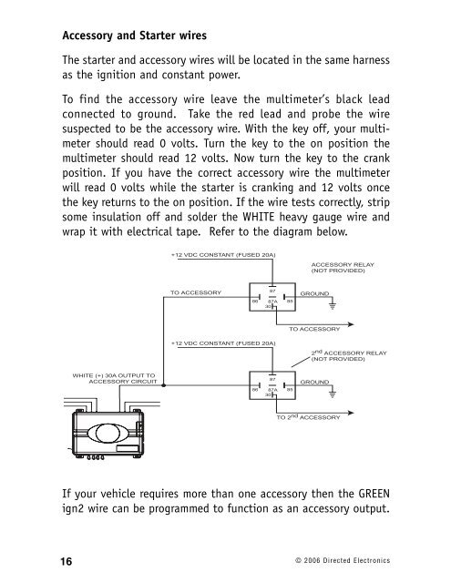
Accessory and Starter wiresThe starter and accessory wires will be located in the same harnessas the ignition and constant power.To find the accessory wire leave the multimeter’s black leadconnected to ground. Take the red lead and probe the wiresuspected to be the accessory wire. With the key off, your multimetershould read 0 volts. Turn the key to the on position themultimeter should read 12 volts. Now turn the key to the crankposition. If you have the correct accessory wire the multimeterwill read 0 volts while the starter is cranking and 12 volts oncethe key returns to the on position. If the wire tests correctly, stripsome insulation off and solder the WHITE heavy gauge wire andwrap it with electrical tape. Refer to the diagram below.+12 VDC CONSTANT (FUSED 20A)ACCESSORY RELAY(NOT PROVIDED)TO ACCESSORY8786 87A 8530GROUNDTO ACCESSORY+12 VDC CONSTANT (FUSED 20A)2 nd ACCESSORY RELAY(NOT PROVIDED)WHITE (+) 30A OUTPUT TOACCESSORY CIRCUIT8786 87A 8530GROUNDTO 2 nd ACCESSORYIf your vehicle requires more than one accessory then the GREENign2 wire can be programmed to function as an accessory output.16 © 2006 Directed Electronics