
You also want an ePaper? Increase the reach of your titles
YUMPU automatically turns print PDFs into web optimized ePapers that Google loves.
0. KIT (FACTORY PRE-ASSEMBLED)At the beginning of each section is an exploded view of the parts to be assembled. There is also alist of all the parts and part numbers that are related to the assembly of that section.The part descriptions are color-coded to make it easier for you to identify the source of a part.Here are what the different colors mean:STYLE A - indicates parts that are included in the bag marked for the section.STYLE B - indicates parts that were set aside in Section 0.STYLE C - indicates parts that are already assembled from previous steps.303013303012303012302019303051301128 (OPTION)301126 (OPTION)903306903306302019KIT30 1126 CHASSIS 3.5MM GRAPHITE - 6-CELL - FOAM-SPEC (OPTION)30 1128 CHASSIS 2.5MM GRAPHITE - 6-CELL - RUBBER-SPEC (OPTION)30 2019 ALU FRONT LOWER SUSP. ADJUST. BULKHEAD30 3012 ALU REAR LOWER SUSP. ADJUST. BULKHEAD30 3013 RIGHT ALU LAYSHAFT BULKHEAD30 3051 MOTOR MOUNT BULKHEAD90 3306 HEX SCREW SFH M3x6 (10)The <strong>XRAY</strong> <strong>T2R</strong> <strong>PRO</strong> comes partially pre-assembled. Before starting assembly, disassemble the chassis parts, noting the position and orientation of the parts,particularly the bulkheads. Keep the parts, including the screw hardware, close at hand. In the assembly steps that follow, each section begins with a parts list. Partsindicated with STYLE B are from the previously disassembled chassis parts in section 0.Lightly file edges of battery slots to removesharp edges.Please note that the optional US Foam-Spec3.5mm Extra-Thick Chassis requires the batteryslots to be filed more than the standard 2.5mmthick chassis.Do not file battery slots too much, or batteriesmay protrude below the chassis bottom.To protect and seal edges of graphite parts, sand edges smooth and then apply CA glue.Do this for: chassis edges; filed battery slots, countersunk holes for front bumper screws.For the optional US extra-thick chassis, we recommend rounding the bottom forward edgeof the chassis (using a file or sandpaper).CORRECTINCORRECTApply only a bit of CA glue onthe countersunk holesCACAFor the optional US extra-thick chassis, we recommend rounding thebottom forward edge of the chassis (using a file or sandpaper).5
1. COMPOSITE BALL DIFF. & FRONT SOLID AXLE930128908275305006941015305083930120305006305184930508305184941015960025305052305135305006305135902310305052902310941015BAG30 5003 ALU BALL DIFFERENTIAL 34T+38T PULLEY - SET (OPTION)30 5006 <strong>T2R</strong> <strong>PRO</strong> COMPOSITE BALL DIFFERENTIAL - SET30 5018 <strong>T2R</strong> <strong>PRO</strong> COMPOSITE DIFF OUTPUT SHAFTS (2)30 5052 COMPOSITE DIFF PULLEY 34T WITH COVERS30 5083 D-LOCK DIFF WASHER - D 17 x 23 x 1 (2)30 5104 <strong>XRAY</strong> MULTI-DIFF (OPTION)30 5135 COMPOSITE SOLID AXLE DRIVESHAFT ADAPTERS (2)30 5136 ALU SOLID AXLE DRIVESHAFT ADAPTERS (2) (OPTION)30 5184 COMPOSITE SOLID AXLE 34T - SET30 5188 COMPOSITE SOLID AXLE 38T - SET (OPTION)90 2310 HEX SCREW SH M3x10 (10)90 8275 HEX SCREW SOCKET HEAD CAP M2.5x25 (10)93 0120 CARBIDE BALL 2.4 MM (12)93 0128 CARBIDE BALL-BEARING AXIAL 2.8x6.5x0.893 0508 BALL-BEARING MR85ZZ 5x8x2.5 (2)94 1015 HIGH-SPEED BALL-BEARING 10x15x4 RUBBER SEALED (2)96 0025 NUT M2.5 (10)930508BB 5x8x2.5930120B 2.4960025N 2.5BEARING OIL(HUDY #106230)OILALIGN FLATSPOTSDiff. Grease(HUDY #106211)908275SCH M2.5x25Diff. Grease(HUDY #106211)930128BA 2.8x6.5ALIGN FLATSPOTSOILBEARING OIL(HUDY #106230)6
COMPOSITE BALL DIFF. & FRONT SOLID AXLE941015BB 10x15x4IMPORTANT: When you build the differential, do not tighten it fully initially; the differential needs to be broken in properly. When you build thediff tighten it very gently. When you put the diff in the car and complete the assembly, run the car for a few minutes, tighten the diff a little bit,and then recheck the diff. Repeat this process several times until you have the diff tightened to the point you want it. Final adjustments shouldALWAYS be made with the diff in the car and on the track.DO NOT TIGHTEN THE DIFF COMPLETELYTHE DIFF MUST BE BROKEN IN <strong>PRO</strong>PERLY!OILBEARING OIL(HUDY #106230)To access the diff when it is installed in the car, you needto remove the front right camber linkage and/or the rearleft camber linkage to detach the front/rear suspensionaccordingly.BEARING OIL(HUDY #106230)OILUse a 2mm hex wrench to adjust the diff.2.0mmAllen DriverASSEMBLED VIEWCOMPOSITE FRONT SOLID AXLEBEARING OIL(HUDY #106230)OILOILBEARING OIL(HUDY #106230)902310SH M3x10941015BB 10x15x4FRONT & REAR AXLES#305003 ALU DIFF 34T + 38T PULLEY#305006 COMPOSITE DIFF 34T PULLEY#305104 <strong>XRAY</strong> ALU MULTI-DIFF#305184 COMPOSITE SOLID AXLE 34T PULLEY#305188 COMPOSITE SOLID AXLE 38T PULLEYCUTAWAY VIEWFRONT & REAR AXLES7
2. FRONT & REAR SUSPENSION309319302044303012302033901408307314303129901308902316303129303013303051302033303163302019302044309319302044302033902314901408902316301128 (OPTION)301126 (OPTION)309319303129307215303129302163302044302033902316901308903306903306903306903306903306903306BAG0230 2033 ALU NUT FOR SUSPENSION HOLDER (2)30 2044 LOWER SUSPENSION HOLDERS (2+2+2)30 2163 FRONT SUSPENSION ARM - HARD - RUBBER-SPEC - 1-HOLE30 2164 FRONT SUSPENSION ARM - EXTRA-HARD - FOAM-SPEC - 1-HOLE (OPTION)30 3129 COMPOSITE SET OF WHEELBASE SHIMS (3x1MM; 1x2MM) (2)30 3131 STEEL SHIM FOR LOWER SUSP. HOLDER 3x7.5x0.4 (10) (OPTION)30 3132 STEEL SHIM FOR LOWER SUSP. HOLDER 3x7.5x0.75 (10) (OPTION)30 3133 STEEL SHIM FOR LOWER SUSP. HOLDER 3x7.5x1.15 (10) (OPTION)30 3134 ALU SHIM FOR LOWER SUSP. HOLDER 3x7.5x1.5 (10) (OPTION)30 3163 REAR SUSPENSION ARM - HARD - RUBBER-SPEC - 1-HOLE30 3164 REAR SUSPENSION ARM - EXTRA-HARD - FOAM-SPEC - 1-HOLE (OPTION)30 7215 FRONT SUSPENSION PIVOT PIN (2)30 7314 REAR SUSPENSION PIVOT PIN (2)30 9319 COMPOSITE UNIVERSAL SET OF SHIMS90 1308 HEX SCREW SB M3x8 (10)90 1408 HEX SCREW SB M4x8 (10)90 2314 HEX SCREW SH M3x14 (10)90 2316 HEX SCREW SH M3x16 (10)90 3306 HEX SCREW SFH M3x6 (10)30 1126 CHASSIS 3.5MM GRAPHITE - 6-CELL - FOAM-SPEC (OPTION)30 1128 CHASSIS 2.5MM GRAPHITE - 6-CELL - RUBBER-SPEC (OPTION)30 2019 ALU FRONT LOWER SUSP. ADJUST. BULKHEAD30 3012 ALU REAR LOWER SUSP. ADJUST. BULKHEAD30 3013 RIGHT ALU LAYSHAFT BULKHEAD30 3051 MOTOR MOUNT BULKHEAD90 3306 HEX SCREW SFH M3x6 (10)8
2. FRONT & REAR SUSPENSION903306SFH M3x6901308SB M3x8L=RREAR ARMSREAR LEFT ARM2.2mmREAR RIGHT ARM901408SB M4x84x8mmL=R3x8mmLEFT REAR ARMCOMPLETED ASSEMBLY3mmREAR DOWNSTOPADJUSTMENTRIGHT REAR ARMREAR ARMS#303163 EU RUBBER-SPEC - HARD (H)#303164 US FOAM-SPEC - EXTRA-HARD (XH)L=RFRONT ARMS901308SB M3x8FRONT RIGHT ARM3.0mmCARPETFRONT LEFT ARM901408SB M4x82.7mmASPHALTCOMPLETED ASSEMBLY4x8mmL=R3mmFRONT LEFT ARMFRONT DOWNSTOPADJUSTMENTFRONT ARMS#302163 EU RUBBER-SPEC - HARD (H)#302164 US FOAM-SPEC - EXTRA-HARD (XH)3x8mmFRONT RIGHT ARM9
2. FRONT & REAR SUSPENSION303129SHIM 3x6x1L=RIt is extremely important that the arms move freelyon the pivot pins. If they do not, use the #107633HUDY Arm Reamer to slightly resize the holes inthe arms.THIN COMPOSITE SHIM3x7x2mmDETAIL303129SHIM 3x6x23x16mm309319SHIM 3x7x2THICK COMPOSITE SHIM3x6x2mmTHIN COMPOSITE SHIM3x6x1mmREAR LEFT ARM902314SH M3x14DETAIL3x14mmUse these suspension holders forinitial assembly902316SH M3x1650.5 mmTOE-IN ADJUSTMENTTRACK WIDTH ADJUSTMENTWHEELBASE ADJUSTMENTROLL CENTER ADJUSTMENTSQUAT ADJUSTMENT2x 1:1Roll Center Position:-0.75mmRoll Center Position:0mmRoll Center Position:+0.75mmFRONT LEFT ARM303129SHIM 3x6x1L=RDETAILDETAIL309319SHIM 3x7x10mmASPHALT+0.75mmCARPETTHIN COMPOSITE SHIM3x7x1mmIt is extremely important thatthe arms move freely on thepivot pins. If they do not, usethe #107633 HUDY ArmReamer to slightly resize theholes in the arms.902316SH M3x163x16mmTHIN COMPOSITE SHIM3x6x1mmTHIN COMPOSITE SHIM3x6x1mmUse these suspension holders forASPHALT initial assemblyFRONT RIGHT ARMUse these suspension holders forCARPET initial assembly3x16mmDETAILTHIN COMPOSITE SHIM3x7x1mmDETAIL+0.75mmCARPET0mmASPHALT47.5 mmTRACK WIDTH ADJUSTMENTWHEELBASE ADJUSTMENTROLL CENTER ADJUSTMENTDIVE ADJUSTMENTRoll Center Position:-0.75mmRoll Center Position:0mmRoll Center Position:+0.75mm2xL=R10
3. CENTRAL TRANSMISSION902306303046 (OPTION)303096 (OPTION)302087 (OPTION)902306902306902306302023302078965050305577981210305784302078302023902306305184940510305521 (OPTION)902304305577940510965050305006302078305444305431BAG0330 2023 ALU UPPER BULKHEAD30 2078 SET OF COMPOSITE HUBS FOR BULKHEADS (4+2)30 2087 SHOCK TOWER FRONT 3.0MM GRAPHITE (OPTION)30 3046 RUBBER-SPEC REAR UPPER DECK GRAPHITE (OPTION)30 3047 FOAM-SPEC REAR UPPER DECK GRAPHITE (OPTION)30 3096 SHOCK TOWER REAR 3.0MM GRAPHITE (OPTION)30 5431 HIGH-PERFORMANCE KEVLAR DRIVE BELT FRONT 3 x 507 MM30 5443 HIGH-PERFORMANCE KEVLAR DRIVE BELT REAR 3 x 186 MM (OPTION)30 5444 HIGH-PERFORMANCE KEVLAR DRIVE BELT REAR 3 x 183 MM30 5521 ALU SOLID LAYSHAFT (OPTION)30 5576 FIXED PULLEY 16T (2) (OPTION)30 5577 FIXED PULLEY 20T (2)30 5778 OFFSET SPUR GEAR 78T / 48 (OPTION)30 5781 OFFSET SPUR GEAR 81T / 48 (OPTION)30 5784 SPUR GEAR 84T / 4830 5787 SPUR GEAR 87T / 48 (OPTION)30 5790 SPUR GEAR 90T / 48 (OPTION)30 5874 OFFSET SPUR GEAR 104T / 64 (OPTION)30 5876 OFFSET SPUR GEAR 106T / 64 (OPTION)30 5878 OFFSET SPUR GEAR 108T / 64 (OPTION)30 5880 OFFSET SPUR GEAR 110T / 64 (OPTION)30 5882 OFFSET SPUR GEAR 112T / 64 (OPTION)30 5884 OFFSET SPUR GEAR 114T / 64 (OPTION)30 5886 OFFSET SPUR GEAR 116T / 64 (OPTION)30 5888 OFFSET SPUR GEAR 118T / 64 (OPTION)90 2304 HEX SCREW SH M3x4 - STAINLESS (10)90 2306 HEX SCREW SH M3x6 (10)94 0510 HIGH-SPEED BALL-BEARING 5x10x4 RUBBER SEALED (2)96 5050 E-CLIP 5 (10)98 1210 PIN 2x10 (10)30 5006 <strong>T2R</strong> <strong>PRO</strong> COMPOSITE BALL DIFFERENTIAL 34T PULLEY - SET30 5184 COMPOSITE SOLID AXLE 34T - SET11
3. CENTRAL TRANSMISSION1. 2. 3.902304SH M3x4965050C5981210P 2x10GEARING ADJUSTMENTNOTE ORIENTATIONOnly when using <strong>XRAY</strong>OFFSET spur gearsCUTAWAYVIEWSPUR GEARS#305778 OFFSET SPUR GEAR 78T / 48P#305781 OFFSET SPUR GEAR 81T / 48P#305784 SPUR GEAR 84T / 48P#305787 SPUR GEAR 87T / 48P#305790 SPUR GEAR 90T / 48P#305874 OFFSET SPUR GEAR 104T / 64P#305876 OFFSET SPUR GEAR 106T / 64P#305878 OFFSET SPUR GEAR 108T / 64P#305880 OFFSET SPUR GEAR 110T / 64P#305882 OFFSET SPUR GEAR 112T / 64P#305884 OFFSET SPUR GEAR 114T / 64P#305886 OFFSET SPUR GEAR 116T / 64P#305888 OFFSET SPUR GEAR 118T / 64P940510BB 5x10x4! IMPORTANTInsert composite bushings perfectlystraight in bulkheads so the bearings spinfreely. If the bearings do not spin freely,reinstall the composite bushings properly.NOTE ORIENTATIONBEARING OIL(HUDY #106230)long beltshort beltOILOILBEARING OIL(HUDY #106230)FRONT BELT TENSION ADJUSTMENTL=RUpper diff position is recommended for tight and technical carpettracks. The upper diff position improves handling in chicanes asit provides more traction, increased steering and makes the careasier to drive.Lower diff position is recommended for large open asphalttracks with long sweepers.REAR BELT TENSION ADJUSTMENTL=RLower diff position is recommended for large open asphalt tracks withlong sweepers.Upper diff position is recommended for tight and technical carpet tracks.The upper diff position improves handling in chicanes as it provides moretraction, increased steering and makes the car easier to drive.ABUPPER DIFF POSITIONLOWER DIFF POSITIONLOWER DIFF POSITIONA B BABAUPPER DIFF POSITIONINITIAL POSITION EU RUBBER-SPECPLACE TAB IN THIS NOTCHINITIAL POSITION US FOAM-SPECPLACE TAB IN THIS NOTCHTO LOOSEN FRONT BELT: Rotate both front nylon hubs in arrow direction (A)TO TIGHTEN FRONT BELT: Rotate both front nylon hubs in arrow direction (B)INITIAL POSITION US FOAM-SPECPLACE TAB IN THIS NOTCHTO LOOSEN REAR BELT: Rotate both rear nylon hubs in arrow direction (A)TO TIGHTEN REAR BELT: Rotate both rear nylon hubs in arrow direction (B)INITIAL POSITION EU RUBBER-SPECPLACE TAB IN THIS NOTCH12
3. CENTRAL TRANSMISSION902306SH M3x6L=RL=R902306SH M3x6! IMPORTANTPosition the rear upper deck inside of the rear drive belt902306SH M3x613
4. STEERING902306902308301183 (OPTION)902306306514302551930407903308902310902310903310307455307455302663301159302663901320302511302663302581or 302583302504302610 (OPTION)307455302504302610 (OPTION)902310930407302551302663FACTORY ASSEMBLEDBAG0430 1159 ALU COUNTERSUNK SHIM (4)30 1183 RUBBER-SPEC UPPER DECK GRAPHITE (OPTION)30 1184 FOAM-SPEC UPPER DECK GRAPHITE (OPTION)30 2504 <strong>XRAY</strong> QUICK-SAVER - ADJUSTABLE SERVO SAVER SET30 2511 <strong>XRAY</strong> QUICK-SAVER - COMPOSITE SERVO SAVER PARTS30 2551 SERVO SAVER PLASTIC COVER - ECCENTRIC (2)30 2581 COMPOSITE SERVO HORN - KO, JR, AIRTRONICS30 2583 COMPOSITE SERVO HORN - FUTABA, ROBE30 2610 ADJ. TURNBUCKLE M3 L/R 40 MM - HUDY SPRING STEEL (2) (OPTION)30 2630 ADJ. TURNBUCKLE L/R 20 MM - HUDY SPRING STEEL (2) (OPTION)30 2652 BALL END 5 MM WITH THREAD (2) (OPTION)30 2663 BALL JOINT 5 MM - OPEN (8)30 6513 ALU LOW TOP DECK MOUNT (2) (OPTION)30 6514 COMPOSITE LOW TOP DECK MOUNT (2)30 7455 PIVOT BALL 5.0 MM DOUBLE BEVEL SHOULDERS (10)90 1320 HEX SCREW SB M3x20 (10)90 2306 HEX SCREW SH M3x6 (10)90 2308 HEX SCREW SH M3x8 (10)90 2310 HEX SCREW SH M3x10 (10)90 3308 HEX SCREW SFH M3x8 (10)90 3310 HEX SCREW SFH M3x10 (10)93 0407 BALL-BEARING MR74ZZ 4x7x2.5 (2)1:1901320SB M3x2064.6mm64.6mm1:1FRONT TOE-IN ADJUSTMENTapproximately 46mmSERVO LINKAdjust servo link to fit your servo2xL=RThere are 5 different Ackermann settings possible with the Quick-Saver903310SFH M3x10ACKERMANN ADJUSTMENTINITIAL POSITION #21 STEP OUT54321For initial Ackermann setting, useStep 2 (2nd shortest length).Step 1 gives the most Ackermann andmakes the car understeer more into andout of corners. It offers good corner speedand creates very good traction mainly inchicanes, because the car is more stable.We recommend using Step 1 on lowtractioncarpet tracks with a lot ofchicanes.5 STEPS OUT54Step 5 gives the least Ackermannand creates a lot of steering intoand out of corners. However, the caris more difficult to drive in chicanesbecause there is less traction andstability.We recommend using Step 5 onhigh-traction asphalt tracks.32114
4. STEERING307455PB 5mmSERVO LINKF = Futaba, RobeK = KO, JR, Airtronics, Sanwa902310SH M3x10RIGHT STEERINGROD 64.6mmLEFT STEERINGROD 64.6mmNOTE position of adjusting pointson turnbuckles (towards outside).Splines for servo on this side(away from linkage)902306SH M3x6902308SH M3x8Install this stand on carpet; the stand willdecrease front traction so that the front tiresdo not overheat too quickly thus preventingthe car from stopping quickly in corners.The stand is not necessary on low-tractionor technical asphalt tracks because the carwill understeer more.DETAILTAB TO FRONT903308SFH M3x8TAB TO FRONTNOTE ORIENTATIONTAB TO FRONT3x8mm3x6mmOILBEARING OIL(HUDY #106230)930407BB 4x7x2.53x6mm3x8mmFor super-high traction tracks and races where thetires have a lot of natural traction (for example: LRPtires, Much More tires, soft compound tires), werecommend using the optional front brace which willmake the car easier to drive with smoother steering.ACKERMANN ADJUSTMENTSTEERING THROW SYMMETRYCHASSIS FLEX SETTINGTOP DECK FLEX SETTING#30205415
5. FRONT & REAR TRANSMISSION303353902306303032302345305241307321901325902310307455302663305326 (OPTION)309319303032902314307455305340307221901302305231980210307455902310302664901325302663302346309319 303363302291305355901304305326 (OPTION)940510901304305340302252305355902310BAG0530 2252 COMPOSITE STEERING BLOCK - MEDIUM - RUBBER-SPEC30 2253 COMPOSITE STEERING BLOCK - HARD - FOAM-SPEC (OPTION)30 2291 STEEL STEERING BUSHING (2+2)30 2345 COMPOSITE C-HUB FRONT BLOCK, RIGHT - 4° DEG.30 2346 COMPOSITE C-HUB FRONT BLOCK, LEFT - 4° DEG.30 2363 C-HUB RIGHT - 4° DEG. - MEDIUM - RUBBER-SPEC (OPTION)30 2364 C-HUB LEFT - 4° DEG. - MEDIUM - RUBBER-SPEC (OPTION)30 2373 C-HUB RIGHT - 4° DEG. - HARD - FOAM-SPEC (OPTION)30 2374 C-HUB LEFT - 4° DEG. - HARD - FOAM-SPEC (OPTION)30 2663 BALL JOINT 5 MM - OPEN (8)30 2664 BALL JOINT 5 MM UNIDIRECTIONAL - OPEN (4)30 3032 ALU QUICK ROLL-CENTER HOLDER 4.9MM (2)30 3122 ALU SHIM 3x6x1.0MM (10) (OPTION)30 3123 ALU SHIM 3x6x2.0MM (10) (OPTION)30 3210 TURNBUCKLE L/R 25 MM - HUDY SPRING STEEL (2) (OPTION)30 3352 UPRIGHT 0° OUTBOARD TOE-IN - MEDIUM - RUBBER-SPEC (OPTION)30 3353 UPRIGHT 1° OUTBOARD TOE-IN - RIGHT - HARD - FOAM-SPEC30 3363 UPRIGHT 1° OUTBOARD TOE-IN - LEFT - HARD - FOAM-SPEC30 5231 DRIVE SHAFT COUPLING - HUDY SPRING STEEL30 5241 DRIVE SHAFT REPLACEMENT PLASTIC CAP 3.5 MM (4)30 5323 DRIVE SHAFT 50MM - HUDY SPRING STEEL (OPTION)30 5324 DRIVE SHAFT 52MM - HUDY SPRING STEEL (OPTION)30 5326 ALU DRIVE SHAFT SWISS 7075 T6 - HARD COATED - 52MM (OPTION)30 5328 ALU DRIVE SHAFT SWISS 7075 T6 - HARD COATED - 50MM (OPTION)30 5325 EQUALIZED CORNERING SPEED (ECS) DRIVE SHAFT 50MM (OPTION)30 5327 EQUALIZED CORNERING SPEED (ECS) DRIVE SHAFT 52MM (OPTION)30 5340 DRIVE AXLE - HUDY SPRING STEEL30 5341 DRIVE AXLE - LIGHTWEIGHT - HUDY SPRING STEEL (OPTION)30 5350 ALU WHEEL HUB (2) (OPTION)30 5351 ALU WHEEL HUB - OFFSET “-0.75MM” (2) (OPTION)30 5352 ALU WHEEL HUB - OFFSET “+0.75MM” (2) (OPTION)30 5353 ALU WHEEL HUB - OFFSET “+1.5MM” (2) (OPTION)30 5355 COMPOSITE WHEEL HUB (2)30 7221 FRONT ARM PIVOT PIN (2)30 7321 REAR ARM PIVOT PIN (2)30 7455 PIVOT BALL 5.0 MM DOUBLE BEVEL SHOULDERS (10)90 1302 HEX SCREW SB M3x2.5 (10)90 1304 HEX SCREW SB M3x4 (10)90 1325 HEX SCREW SB M3x25 (10)90 2306 HEX SCREW SH M3x6 (10)90 2310 HEX SCREW SH M3x10 (10)90 2314 HEX SCREW SH M3x14 (10)94 0510 HIGH-SPEED BALL-BEARING 5x10x4 RUBBER SEALED (2)98 0210 PIN 2x10 (10)901302SB M3x2.54x1.5MM ALLENWRENCHDO NOTOVERTIGHTEN! IMPORTANTDO NOT use the plastic caps withcomposite solid axle included inthe kits.DRIVE SHAFTS#305323 US FOAM-SPEC - 50MM - STEEL#305324 EU RUBBER-SPEC - 52MM - STEEL980210P 2x10The new #305241 3.5mm plasticcaps are for use ONLY in REARwith <strong>T2R</strong> <strong>PRO</strong> COMPOSITE ball diffor with ALU ball diffs or the <strong>XRAY</strong>Multi-Diff.#305325 ECS US FOAM-SPEC - 50MM - STEEL#305326 EU RUBBER-SPEC - 52MM - ALU#305327 ECS EU RUBBER-SPEC - 52MM - STEEL#305328 US FOAM-SPEC - 50MM - ALUTHREADLOCKTLDrive shafts may be combined. For example, you may use the longer 52mm shafts with the optionalUS Foam-Spec chassis, and the shorter 50mm shafts with the EU Rubber-Spec chassis. However, werecommend using the drive shafts that are included in the kit since the drive shaft lengths have beencarefully chosen to optimize speed and ease of driving.DO NOTOVERTIGHTENGRAPHITE GREASE(HUDY #106210)Longer drive shafts (52mm) make the car easier to drive because they give more traction and betterstability, mainly in chicanes. However, car will understeer more than with shorter (50mm) shaftswhich give a lot of steering and impart aggression to the car. You may also combine differentlengths of shafts in front and rear (for example, using long shafts in the rear and short shafts in thefront) depending on track conditions.52MM DRIVE SHAFTSARE INCLUDED IN KITBoth left & right shafts should ALWAYS be the same length at one end of the car (front or rear).16
5. FRONT & REAR TRANSMISSION2xOILBEARING OIL(HUDY #106230)UPRIGHTS#303351 1° - RIGHT - MEDIUM - RUBBER-SPEC940510BB 5x10x4#303352 0° - R/L - MEDIUM - RUBBER-SPEC#303353 1° - RIGHT - HARD - FOAM-SPEC#303354 0° - R/L - HARD - FOAM-SPEC980210P 2x10#303361 1° - LEFT - MEDIUM - RUBBER-SPEC#303363 1° - LEFT - HARD - FOAM-SPEC#303358 ALU 1° - R/L#303359 ALU 2° - R/LCOMPLETEDASSEMBLYREAR TOE-IN ADJUSTMENT2xOILBEARING OIL(HUDY #106230)L=RLEFT STEERING BLOCK = RIGHT STEERING BLOCK940510BB 5x10x4980210P 2x10L=RCOMPLETEDASSEMBLYSTEERING BLOCKS#302252 MEDIUM - RUBBER-SPEC#302253 HARD - FOAM-SPEC#302256 ALUWHEEL HUBS#305350 ALU - OFFSET 0 MM#305351 ALU - OFFSET -0.75 MM#305352 ALU - OFFSET +0.75 MM#305353 ALU - OFFSET +1.5 MM902310SH M3x102xSHORTLONGCOMPLETED ASSEMBLYRIGHT C-HUB "4R"LEFT C-HUB "4L"C-HUBS#302334 ALU 0° - R+L#302335 ALU 2° - RIGHT#302336 ALU 2° - LEFT#302337 ALU 4° - RIGHT#302338 ALU 4° - LEFT#302339 ALU 6° - RIGHT#302340 ALU 6° - LEFT#302343 COMPOSITE 2° - RIGHT#302344 COMPOSITE 2° - LEFT#302345 COMPOSITE 4° - RIGHT#302346 COMPOSITE 4° - LEFT#302347 COMPOSITE 6° - RIGHT#302348 COMPOSITE 6° - LEFT#302361 2°- RIGHT - MEDIUM - RUBBER-SPEC#302362 2°- LEFT - MEDIUM - RUBBER-SPEC#302363 4°- RIGHT - MEDIUM - RUBBER-SPEC#302364 4°- LEFT - MEDIUM - RUBBER-SPEC#302365 6°- RIGHT - MEDIUM - RUBBER-SPEC#302366 6°- LEFT - MEDIUM - RUBBER-SPEC#302371 2°- RIGHT - HARD - FOAM-SPEC#302372 2°- LEFT - HARD - FOAM-SPEC#302373 4°- RIGHT - HARD - FOAM-SPEC#302374 4°- LEFT - HARD - FOAM-SPEC#302375 6°- RIGHT - HARD - FOAM-SPEC#302376 6°- LEFT - HARD - FOAM-SPECCASTER ADJUSTMENT17
5. FRONT & REAR TRANSMISSION901325SB M3x254xSPECIAL UNIDIRECTIONAL BALL-JOINTWITH MOLDED DOTFACTORY PREASSEMBLED4xMOLDED DOT4xL=RFRONT RIGHT = FRONT LEFTREAR RIGHT = REAR LEFTL=RCAMBER ADJUSTMENT53 mm1:152.3 mm309319SHIM 3x5x1"1R"307455PB 5mmL=R(52.3 mm)3x6mm901304SB M3x43x10mm902306SH M3x6COMPOSITE SHIM3x5x1mmINITIAL POSITIONUse inner hole25 mm"1L"902310SH M3x101:12xTIGHTEN GENTLYDETAIL STEPAfter you tighten the screw intothe upright, pull the linkageupward so the ball joint "snaps"onto the pivot ball. The wholeassembly should move freely."CLICK"3 +4 32 14+INITIAL POSITION3+ 4 +3142Quick Roll Center TM tabs in upper inner holesROLL-CENTER ADJUSTMENTQuick Roll Center positions guidelinefor use in the T2’008 SET-UP SHEET.3+ 4+31423+ 4+31423+ 4+31423+ 4+31423+ 4+31423+ 4+314218
5. FRONT & REAR TRANSMISSION309319SHIM 3x5x1307455PB 5mm4 32 13142901304SB M3x4INITIAL POSITIONQuick Roll Center TM tabs in upper inner holes902306SH M3x6"4R"L=R(53 mm)3x14mm902314SH M3x14Use the composite 3x5x1mm shim.When using these shims, use theupper roll center positions on thefront shock tower.3x6mm"4L"DETAIL STEP"CLICK"23 mmTIGHTEN GENTLYAfter you tighten the screw into the steering block, pullthe linkage upward so the ball joint "snaps" onto thepivot ball. The whole assembly should move freely.1:1 2xROLL CENTER ADJUSTMENT307455PB 5mmFREE MOVEMENTFREE MOVEMENTINITIAL POSITION902310SH M3x10L=RACKERMANN ADJUSTMENT19
6. SHOCK ABSORBERS303241308352308331308090308080<strong>XRAY</strong> SPRINGS#308373 C = 2.2 (2)#308374 C = 2.4 (2)#308375 C = 2.6 (2)#308376 C = 2.8 (2)#308377 C = 3.0 (2)#308378 C = 3.2 (2)#308379 C = 3.4 (2)308331970121<strong>XRAY</strong> SPRINGS#308390 SPRING SET (24)#308393 (14 LB) YELLOW - SUPER-SOFT (4)#308394 (17.5 LB) WHITE - SOFT (4)#308395 (22.5 LB) BLUE - SOFT-MEDIUM (4)#308396 (28 LB) VIOLET - MEDIUM (4)#308397 (33 LB) PURPLE - MEDIUM-HARD (4)#308398 (38 LB) RED - HARD (4)#308380 ADDITIONAL SPRING SET (20)#308384 (15 LB) BLUE-GREEN (4)#308385 (20 LB) LIGHT-BLUE (4)#308386 (25 LB) DARK-BLUE (4)#308387 (30 LB) LIGHT-PURPLE (4)#308388 (35 LB) LIGHT-RED (4)308035308040#308382 (14 LB) GOLD (4)#308383 (17.5 LB) SILVER (4)308382 (GOLD) (REAR)308383 (SILVER) (FRONT)965019308035ADJUSTABLE1-4 HOLES971031970050308035NON-ADJUSTABLE961032965023ADJUSTABLE PISTONS2 HOLES308362NON-ADJUSTABLE PISTONS3 HOLES3083314 HOLES308316303241BAG30 3241 BALL UNIVERSAL 5.8 MM HEX (4)30 8035 COMPOSITE PISTONS ADJUSTABLE + NON-ADJUST. (SET 2+6)30 8040 SHOCK ADJ. NUT ALU + O-RING (4+4)30 8080 SHOCK ABSORBER MEMBRANES (4)30 8090 SHOCK FOAM INSERTS (4)30 8302 <strong>XRAY</strong> SHOCK ABSORBER-SET 4-STEP - SHORT (2)30 8306 <strong>XRAY</strong> ALU SHOCK ABSORBER-SET (2) (OPTION)30 8316 SHOCK BALL JOINT - OPEN (4)30 8331 COMPOSITE FRAME SHOCK PARTS 4-STEP - SHORT30 8352 ALU SHOCK CAP-NUT WITH VENT HOLE (2)30 8362 HARDENED SHOCK SHAFT - SHORT (2)30 8380 ADDITIONAL <strong>XRAY</strong> ULTIMATE RACING SPRINGS (20) (OPTION)30 8390 <strong>XRAY</strong> SELECTED ULTIMATE RACING SPRINGS (24) (OPTION)30 8382 <strong>XRAY</strong> <strong>PRO</strong>GRESSIVE SPRING-SET D=1.4 (14 LB) GOLD (4)30 8383 <strong>XRAY</strong> <strong>PRO</strong>GRESSIVE SPRING-SET D=1.5 (17.5 LB) SILVER (4)96 1032 WASHER S 3.2 (10)96 5019 E-CLIP 1.9 (10)96 5023 E-CLIP 2.3 (10)97 0050 O-RING 5x1 (10)97 0121 O-RING 12.1x1.6 (10)97 1031 SILICONE O-RING 3.1x1.6 (10)ADJUSTABLE PISTONSSHOCK OILCarefully remove the shock pistons from theframe, and remove all excess plastic flashADJUSTABLE PISTONSNON-ADJUSTABLE PISTONS961032S 3.2INITIAL ASSEMBLY965019C 1.9ALTERNATIVE965023C 2.3965019C 1.9965023C 2.320
6. SHOCK ABSORBERSSHOCK OILCUTAWAY VIEW970121O 12.1x1.6SHOCK OILSHOCK OILBe careful not to cross-thread thecollar on the shock body.970050O 5x1SHOCK OILOPTIONAL SHOCK TOOL(HUDY #183010)971031O 3.1x1.61mmINCORRECTCORRECTDETAILUSE ONLY separate ball-joints (part #308316).HINT: Pre-thread the ball joint using an M3 screw.WARNING! Be careful not to pre-thread too far, since theball joint may split or the plastic threads may strip outSHOCKOILSHOCK FILLINGFully extend the piston rod so the piston is at the bottom of the shock body.Hold the shock upright and slightly overfill the shock body with shock oil.Let the oil settle and allow air bubbles to rise to the top. Slowly move the piston up and down untilno more air bubbles appear. Add shock oil as necessary.Pull the piston rod most of the way out of the shock body. Let the shock rest for 5 minutes to allowthe air bubbles to escape.CUTAWAY VIEWFOAMINSERTAfter you insert the membrane ensure thatit sits properly all around the alu cup.SHOCK DAMPINGWhen installing the shock cap assemblyon the shock body, some oil will leak out...this is normal.Fully tighten the cap and clean off anyexcess oil.After the shock is assembled, the shockrod will push itself out of the shock bodyfairly quickly.Follow the next procedure to adjust therebound.SHOCK OILS#359210 100cSt (<strong>XRAY</strong> 20W)#359215 150cSt#359220 200cSt (<strong>XRAY</strong> 25W)#359225 250cSt#359230 300cSt#359235 350cSt (<strong>XRAY</strong> 30W)#359240 400cSt#359245 450cSt#359250 500cSt#359260 600cSt (<strong>XRAY</strong> 35W)#359270 700cSt#359280 800cSt#359290 900cSt#359301 1000cSt (<strong>XRAY</strong> 40W)#359302 2000cSt (<strong>XRAY</strong> 50W)EFFECTS OF SHOCKDAMPING21
6. SHOCK ABSORBERSREBOUND ADJUSTMENTREBOUND CHECKRELEASETIGHTENREBOUND0%25%50%75%After the shock is assembled you have to set the Shock Rebound.1. Release the shock composite lower cap.2. VERY SLOWLY do the following: Fully pull out the shock rod, push it back in fully, and then fully pullit out once more. Repeat this procedure the following number of times to achieve the desired ShockRebound setting:10 times - approximately 75% rebound (high rebound - suggested for very low traction track)15 times - approximately 50% rebound (medium rebound - suggested for standard track)20 times - approximately 25% rebound (low rebound - suggested for very high traction track)During the Rebound Adjustment procedure shock oil will leak out of the shock body through the O-ringon the shock rod... this is normal. During the Rebound Adjustment procedure DO NOT open the uppershock cap.100%3. After you have set the Rebound Adjustment, re-install the shock lower composite cap.4. Check the Shock Rebound setting by pushing the shock rod fully into the shock body, releasing it, andobserving how far the shock rod extends by itself:* 25% out of the shock body (low rebound)* 50% out of the shock body (medium rebound)* 75% out of the shock body (high rebound).If the shock rod rebounds too much, return to Step 1 and repeat the procedure.If the shock rod does not rebound enough, you will have to refill the shock with shock oil, and then repeatthe bleeding and Shock Rebound procedures.Cutaway view ofassembled shock absorberCHECK NEXTTECH TIPFRONT SHOCKS(Silver)SHOCK DAMPINGADJUSTMENTSPRING RATE SELECTIONTECH TIPFollow this tech tip to properly install pivot ballsinto the top pivot and bottom ball joint.Parts Needed:• M3 x 16 SH screw• M3 shimNote that the composite parts have two sides,noticeable around the pivot ball hole: one sidehas a shiny finish, the other side has a regularfinish.SHINYFINISH SIDESOFTEST432HARDEST1SHINYFINISH SIDEShock length adjustment:It is VERY important that all shocks are equal length.Fully extend the shock absorber and measure the end-to-endlength; we recommend using digital calipers to give an accuratemeasurement. If a shock absorber is shorter or longer than others,adjust the shock length by tightening or loosening the ball joint onthe shock rod.Damping adjustment:If you built the adjustable shocks, fully extend the shock rod and turn itslightly to lock the piston in the shock body.Turning the shock rod fully CCW aligns 4 holes in the pistons (softestdamping). Turning the shock rod fully CW aligns 1 hole in thepistons (hardest damping). The shocks have four settings, each ofwhich can be felt by a slight "click".Set all four shocks initially to position 3 (3 holes open): turn fullyCCW, then turn CW by 1 click.Install pivot balls into top pivot orlower ball joint as shown, on theproper sides.Note that the lower pivot ball hasan extra shoulder.REAR SHOCKS(Gold)Tighten screw until pivot ballsnaps into placeSHINYFINISH SIDEEnsure pivot balls move freelySHINYFINISH SIDERemove screw and shim22
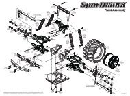
7. FRONT & REAR ASSEMBLY903308301218301222902306301322308302981212301322301203903310903308960030903310BAG0730 1202 COMPOSITE BUMPER (OPTION)30 1203 IMPACT ABSORBING FRONT BUMPER30 1218 COMPOSITE UPPER HOLDER FOR BUMPER30 1322 FRONT BODY MOUNT SET 6MM90 2306 HEX SCREW SH M3x6 (10)90 3308 HEX SCREW SFH M3x8 (10)90 3310 HEX SCREW SFH M3x10 (10)96 0030 NUT M3 (10)98 1212 PIN 2x12 (10)30 1222 FOAM BUMPER30 8302 <strong>XRAY</strong> SHOCK ABSORBER-SET 4-STEP - SHORT (2)903308SFH M3x8903310SFH M3x10960030N M3x103x10mm3x10mm3x8mm3x10mm23
7. FRONT & REAR ASSEMBLY903308SFH M3x8L=R981212P 2x12INITIAL POSITION902306SH M3x6INITIAL POSITIONL=ROPTIONAL #308019 Composite Set of Shock Shims & Nuts:To make the car more stable and easier to drive, move the front shocks forward. Stabilityincreases mainly in chicanes. Note that the car will have less steering into corners.FRONT SHOCK(Silver)• Upper mount (shock tower): Add a plastic nut and use a longer screw 3x8mm (NOTINCLUDED) to space the upper end of the shock away from the shock tower.SHOCK POSITION ADJUSTMENTRIDE HEIGHT ADJUSTMENTDROOP ADJUSTMENT• Lower mount (lower arm): Add shims and use a longer setscrew 3x10mm (NOTINCLUDED) on the lower arms to space the lower end of the shock away from the arm.24
7. FRONT & REAR ASSEMBLY301332902306981212902308981212308302BAG0730 1332 REAR BODY MOUNT SET 6MM90 2306 HEX SCREW SH M3x6 (10)90 2308 HEX SCREW SH M3x8 (10)98 1212 PIN 2x12 (10)30 8302 <strong>XRAY</strong> SHOCK ABSORBER-SET 4-STEP - SHORT (2)L=R902308SH M3x8981212P 2x12INITIAL POSITION902306SH M3x6INITIAL POSITIONL=ROPTIONAL #308019 Composite Set of Shock Shims & Nuts:To make the car more stable and easier to drive, move the front shocks forward. Stabilityincreases mainly in chicanes. Note that the car will have less steering into corners.• Upper mount (shock tower): Add a plastic nut and use a longer screw 3x8mm (NOTINCLUDED) to space the upper end of the shock away from the shock tower.REAR SHOCK(Gold)SHOCK POSITION ADJUSTMENTRIDE HEIGHT ADJUSTMENTDROOP ADJUSTMENT• Lower mount (lower arm): Add shims and use a longer setscrew 3x10mm (NOTINCLUDED) on the lower arms to space the lower end of the shock away from the arm.25
8. FINAL ASSEMBLY306310306131NOT INCLUDEDNOT INCLUDED306210903308903306306300903308FROM SERVO309402902308306219NOT INCLUDED902306960140NOT INCLUDED960140903308903308BAG07305912~88 NARROW PINION GEAR ALU HARD COATED (OPTION)30 6131 SET OF BATTERY BACKSTOPS - V230 6163 6-CELL GRAPHITE BATTERY STRAP (SET) - (OPTION)30 6200 ALU SERVO MOUNT (2) (OPTION)30 6210 COMPOSITE SERVO MOUNT (2)30 6219 COMPOSITE SET OF SERVO SHIMS (4)30 6300 ANTENNA MOUNT30 9402 BODY CLIP FOR 6MM BODY POST (4)90 2306 HEX SCREW SH M3x6 (10)90 2308 HEX SCREW SH M3x8 (10)90 3306 HEX SCREW SFH M3x6 (10)90 3308 HEX SCREW SFH M3x8 (10)96 0140 NUT M4 WITH FLANGE (10)30 6310 ANTENNA (2)For improved weight balance, we recommendusing a narrow, light servo.SERVO NOT INCLUDEDFROM SERVO306219SHIM 3x6x1306219SHIM 3x6x2306219SHIM 3x6x390°Install servo using 4 identical shims ofsame thickness between the servo tabsand the mounting posts in order the servoarm does not touch the top deck. Thereare 3 different thicknesses of the shims.DETAIL902308SH M3x8903308SFH M3x8Attach servo arm to servo output shaftusing screw from servo.Servo arm must be perpendicular tolinkage when servo is in neutral.1mm2mm3mm26
8. FINAL ASSEMBLY902306SH M3x6When installing the motor on the bulkhead, rotate the spur gear so the motor screw can be installed througha hole in the spur gear. See the detail image below.Adjust the motor so the pinion meshes with the spur gear properly. Make sure the gear mesh is not too tight.There should be a small amount of play between the teeth of the pinion gear and spur gear.DETAILSuggested to use3x2.5mm set screwPINION(NOT INCLUDED)GEARING ADJUSTMENTMOTOR(NOT INCLUDED)RECEIVER(NOT INCLUDED)903308SFH M3x8SPEED CONTROLLER(NOT INCLUDED)DOUBLE-SIDED TAPE(NOT INCLUDED)Feed the receiver wire into the antenna tubeBATTERY ASSEMBLY CONFIGURATION6-CELL ALTERNATIVE903306SFH M3x6903308SFH M3x83x8mm3x6mm3x8mm3x6mm27
8. FINAL ASSEMBLYBATTERY ASSEMBLY CONFIGURATION5-CELL REAR POSITION ALTERNATIVE5-CELL FRONT POSITION ALTERNATIVE4xWHEELS & TIRES & INSERTS(NOT INCLUDED)CAWARNING!Follow the adhesive manufacturer's instructionsfor proper use and safety. Wear proper eye andhand protection.FOAM TIRE TIPSUS Foam-Spec Notice:Some foam wheels may be slightly wider and may touch the front steering blocks. Toavoid this, we recommend grinding the inside edge of the wheel, using a tire truerand a file. Make sure that both front tires/wheels end up being the same width, andthat there are no rough edges.Also, make sure that the front wheels and tires do not touch the steering blocks whenthe steering is turned, and that the wheels and tires do not touch the shocks.We recommend using #107870HUDY Fibre Reinforced Tape5-CELL OR 6-CELL INLINE BATTERY PACK(NOT INCLUDED)960140N M4or the optional battery holders:#306163 <strong>XRAY</strong> Graphite Battery Holder (for 6-cell chassis)DETAILFIBRE TAPE(HUDY #107870)(NOT INCLUDED)RIDE HEIGHT ADJUSTMENTDROOP ADJUSTMENTMake sure the wheel nuts are very tight, so thewheels do not loosen during racing.28
LIPO CONVERSION SETBecause of enormous increase in Lipo batteries popularity, <strong>XRAY</strong> is the first car which is introducing Lipo conversion set. Thanks to the conversion, carscan be powered by the most used and popular Lipo batteries.3x6(from kit)Do not use the standard reartop deck from the kit.3x8301183(from kit)3011863x8NOTE! The LiPo Conversion Setallows for the fitting of popularLiPo battery packs with a height of24.5mm or less (the most popularand common configuration andsizing available on the marketat the time of development).However, because of continuingdevelopment of LiPo batteries andno set of standardized regulationsabout battery sizes, <strong>XRAY</strong> cannotguarantee that all LiPo batterypacks will fit in the cars using thisconversion set.301186BAG08LiPo Battery Fitting Because LiPo batteries are also different in the width, it is important to correct the length of ESC wiring so that the batteryconnectors can easily be connected to the batteries. If the battery connectors cannot be connected because the top deck is in the way, please follow themodification shown in the pictures.CUTSOLDERFibre Tape(HUDY #107870)Pinion AssemblyBecause of the LiPo battery width, it is important to check that the motor pinion is not touching the battery. If the piniontouches the battery (or is close to touching it), move the pinion closer to the motor. It is sufficient to have only half of the pinion teeth contacting the spurgear teeth. This has no effect on the car’s speed or performance.min. 1mmLiPo batteryPinionDETAIL29
Multi-Flex TechnologyThe <strong>T2R</strong> <strong>PRO</strong> has 3 kinds of Multi-Flex settings: soft, medium, and stiff. The amount of stiffness used depends on the track surface.Car on CarpetIf you drive on carpet, we do not recommend using the soft Multi-Flex setting, while on the other end of spectrum if you drive on asphalt, we do not recommendusing the stiff Multi-Flex setting. The reason why a soft setting should not be used on carpet is that although it may be a low-traction track, the carpet can overheatthe front tires and make car very difficult to drive. As such, we recommend using a medium Multi-Flex setting if you drive on a low-traction carpet track. When oncarpet, it is very important to use all four screws in the front part of the top deck. Although you may feel that car is more reactive using only 2 screws there, as wasalready mentioned above, it may lead to tire overheating. We recommend using the front central alu stand on carpet because it makes the car more stable andeasier to drive. On very technical tracks with low traction, you may remove the alu central stand to get more steering, but be careful when the traction increases…you may have to use the alu central stand again.If you decide to attend large race events with many participants, you can expect super-high traction. In these conditions, we recommend using not only the frontstand but also the front optional chassis brace which makes the car easier to drive. However, the optional front brace decreases front traction and steering. Thestiff setting can be used on super-high traction tracks when you want to increase the “aggression” of the car. If you want to increase steering you can do this bydecreasing the rear traction; in that case, the screw under the motor holder may be used and/or you may tighten all screws in the rear bulkheads.Car on AsphaltWhen running the car on asphalt, completely different settings are used compared to carpet. Typically, asphalt has low–medium traction so the soft and mediumsettings are generally recommended. Asphalt usually does not overheat the front tires as much as carpet does, however tire overheating on asphalt may occurwhen the track is super-hot and when soft inserts and/or soft tire compound are used. Normally you can use the soft setting for low-traction tracks. If the track isvery technical, we recommend using the soft setting mainly for the front suspension, because the soft front suspension creates more aggression in the car. For thisreason, we recommend using only 2 screws in the front part of the top deck, and no central alu stand. Screws from the front bulkheads may be removed as well.If you remove the rear screws on the front bulkheads, the car will steer better into corners.Car Summary:• Stiff setting: Very-high traction carpet track• Medium setting: Technical medium traction carpet or asphalt track• Soft setting: Technical or low-traction asphalt trackSOFT SETTINGscrew not usedscrew usedMEDIUM SETTINGscrew not usedscrew usedSTIFF SETTINGscrew not usedscrew used30
1RACETRACKNAMECITY /COUNTRYCONTACTDATETEMPERATURE /°F or °CQUALIFYING POSITION BEST LAPTIME / sec FINAL POSITION RACE LENGTH / minutesAIRTRACKFRONTCASTERDIVE ROLL-CENTERRIDE HEIGHT/mm0 o 2 o 4 o 6 oSHIM/ mm+0.75+0.75 +0.750.000.00 0.00- 0.75- 0.75 - 0.75WHEELBASE/mmSQUAT ROLL-CENTER0 1 121 0RIDE HEIGHT/mmREAR+0.750.00- 0.75TRACK CONDITIONTRACTIONFRONT PULLEYSOLID AXLEFRONTPINION / TFINAL DRIVE RATIOTECHNICAL MIXEDFASTLOW MEDIUM HIGHTRANSMISSIONDIFF.LOOSE MEDIUM TIGHTLOOSE MEDIUM TIGHTONE WAY DIFFERENTIAL YESSOLID ONE WAY DIFF. YESMIDDLE ONE WAY PULLEYYESFIXEDFRONTALUPLASTIC SHOCKS<strong>XRAY</strong> SPRINGS#308393 Super SoftYELLOW#308384BLUE-GREEN#308394 SoftWHITE#308385LIGHT-BLUE#308395 Soft Medium BLUE#308386DARK-BLUE#308396 MediumVIOLET#308387LIGHT-PURPLE#308397 Medium Hard PURPLE#308388LIGHT-RED#308398 HardREDCARPETSPUR GEAR / TROLLOUTALUREARREAR(D=1.4)(D=1.5)(D=1.5)(D=1.6)(D=1.6)(D=1.7)(D=1.7)(D=1.8)(D=1.8)(D=1.9)(D=1.9)ONE-WAYASPHALTREAR PULLEYPLASTIC14 lb15 lb17.5 lb20 lb22.5 lb25 lb28 lb30 lb33 lb35 lb38 lbC-HUBMHALUSTEERING BLOCKMHALUOFFSETSTANDARDFRONTOUTINFRONT10 98 7SHIM UNDER SHOCKSHIM /mmSHIM FRONTSHIM /mmSHIM REARSHIM /mm65SHIM4/ mm3LONGSHORTMEASURE UNDER ARM2OUTERACKERMANNPOSITIONINNERACKERMANNPOSITION5 4 3 2 1420 -1 -212345121 2UPPER SHOCK POSITION31TOE / degr. FINAL TOE IN OUTBOARD TOESERVO SAVER3+ 4 +31QUICK ROLLCENTER POSITIONDOWNSTOP / mmCAMBER / degr.12345 642-3OUTBOARD+INBOARD TOESHIM FRONT/REAR1.5 mmNO shimOTHERLONGSHORT-2ANTI ROLL-BAR-1SHIM UNDER SHOCKSHIM /mm0112SHIM/ mmCAMBER LINKLOCATION2 3 4 5 6 7 8 9 1021MEASURE UNDER ARMINBOARD SHIMS ARE USED IN ADDITION TO TRACK-WIDTH SHIMSREAR HUBINBOARD TOE1.51.150.750.4MHALUOFFSETSTANDARD2.251.9REARREARSHIM / mm=3 o=2.5 o=2 o=1.5 o=1 o=0.5 o0 =0o#308373#308374#308375#308376#308377#308378#308379C 2.2C 2.4C 2.6C 2.8C 3.0C 3.2C 3.4FRONT ARMHARD (H)EXTRA-HARD (XH)HARD (H)REAR ARMEXTRA-HARD (XH)OTHER SPRINGOIL / CSTLENGTH / mmPRELOAD / mmREBOUND %YES NO FOAM INSERTSYES NOBALANCE / gTOP DECK MULTI-FLEX SETTINGUS TOP DECKBALANCE / gYES NO O-RING ON SHAFTYES NOOPENEDCLOSEDTHICKNESS / mmHOLESIN PISTONANTI-ROLL BARTIRESDIAMETER / mmINSERTSTHICKNESS / mmECCENTER/mmSTANDARDDIFF.POSITIONUPDOWN1BALANCE / gEU TOP DECKECCENTER/mmSTANDARDDIFF.POSITIONUPDOWN1BALANCE / gADDITIVEFRONT LEFTFRONT RIGHTTREATED AREAREAR LEFTREAR RIGHTFRONTCHASSIS MULTI-FLEX SETTINGCHASSISREARWHEELSS M HMOTORHARDNESSARMATURE+ SPRING -+ BRUSH COMP. -S M HCENTRALALU STANDESCBATTERIESBRUSHLESS <strong>PRO</strong>GRAM PUNCH INITIAL BRAKE AUTO BRAKEBODYWING- APPLIED S -SOFT M -MEDIUM H -HARDFRONT ALUSTANDS (US)BRACE (EU)REAR ALUSTANDS (US)VER 5 0c<strong>XRAY</strong>