CD80 Advanced Electronics Rack User Manual - The Strand Archive
CD80 Advanced Electronics Rack User Manual - The Strand Archive
CD80 Advanced Electronics Rack User Manual - The Strand Archive

You also want an ePaper? Increase the reach of your titles
YUMPU automatically turns print PDFs into web optimized ePapers that Google loves.
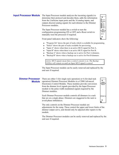
Input Processor Module<strong>The</strong> Input Processor module analyzes the incoming signal(s) todetermine their protocol and decodes them, adds the informationfrom the LiteScene input ports and the 16 analog inputs, andoutputs discreet analog signals for each dimmer to the DimmerProcessor modules.<strong>The</strong> Input Processor module has a switch to turn theconfiguration programming ON or OFF and a Reset switch tomanually reset the processor if required.Front panel indicators show the following: "Program On" shows the pair of racks which is available for programming. "Select" shows the pair of racks available for previewing. "Input A" shows when there is an active MUX signal for Port A. "Input B" shows when there is an active MUX signal for Port B. "Backup A" shows when a backup cue is active for Port A dimmers. "Backup B" shows when a backup cue is active for Port B dimmers.Active MUX signals mean that a control console is on. <strong>The</strong> BackupLED(s) will remain on until an Input MUX signal is sensed.<strong>The</strong> Input Processor module can be easily removed and replaced by theend user if required.Dimmer ProcessorModule<strong>The</strong>re are either 3 (for single rack operation) or 6 (for dual rackoperation) Dimmer Processor Modules in a <strong>CD80</strong> <strong>Advanced</strong><strong>Electronics</strong> Control Module. <strong>The</strong>se modules provide conversionfrom the dimmer level signals provided by the Input Processormodule to the pulse width modulated signals required by theDimmer modules.Each Dimmer Processor module controls all dimmers in a rackthat are on a single phase. Dimmers are staggered in the rack toavoid phase imbalances.<strong>The</strong> only controls on the Dimmer Processor module areadjustments for the ramp. <strong>The</strong>se control the upper and lower limits of thedimmer output curve, and should only be adjusted after repairs to themodule.<strong>The</strong> Dimmer Processor modules can be easily removed and replaced by theend user if required.Hardware Description 9