CD80 Advanced Electronics Rack User Manual - The Strand Archive
CD80 Advanced Electronics Rack User Manual - The Strand Archive
CD80 Advanced Electronics Rack User Manual - The Strand Archive

You also want an ePaper? Increase the reach of your titles
YUMPU automatically turns print PDFs into web optimized ePapers that Google loves.
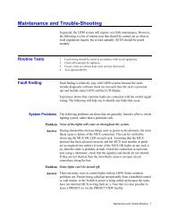
Dimmer ProcessorCard Calibration<strong>The</strong> calibration for the Dimmer Processor card should not be attemptedunless you have a schematic of the board.Refer to the schematic. <strong>The</strong>re are 4 adjustable pots; R1, R2, R10, and R32.Only R1 (Ramp gain) and R2 (Ramp Bias) are accessible from the front ofthe system. Adjusting R10 (Line Center) and R32 (Line Compensation)requires that the PC board be outside the rack on an extender board orcable and should be done only by <strong>Strand</strong> technicians.Ramp Gain and BiasAdjustment in the Field<strong>The</strong> Ramp gain and bias for a Dimmer Processor module should bechecked whenever a spare is put into the system or a repaired unit returnedfrom <strong>Strand</strong>. You will be repeating the following procedure while viewingthe output of the odd dimmer in the following dimmer slots: <strong>Rack</strong> A slot 1 (for Dimmer Processor module #1) <strong>Rack</strong> A slot 2 (for Dimmer Processor module #3) <strong>Rack</strong> A slot 3 (for Dimmer Processor module #5) <strong>Rack</strong> B slot 1 (for Dimmer Processor module #2) <strong>Rack</strong> B slot 2 (for Dimmer Processor module #4) <strong>Rack</strong> B slot 3 (for Dimmer Processor module #6)Turn all dimmer circuit breakers in the rack to be adjusted OFF. Removethe first row of dimmers from the dimmer rack. Set up control from theconsole, the programmer, or a LiteScene station so that all of the aboveslots can be taken from ZERO to FULL as required.Use an oscilloscope to view the control output for the odd dimmer (thirdpin down on the dimmer receptacle in the rack) in the appropriate slot asyou adjust the Dimmer Processor module.1. Set dimmers to ZERO. Adjust R2 'RAMP BIAS' on Dimmer Processormodule so that the control output pulse width is just a positive spike.Continue adjusting it until just past the point where the spike disappears andthe output is flat at zero volts.2. Set dimmers to FULL. Adjust R1 'RAMP GAIN' until the control output ishigh with just a spike to zero volts. Continue adjusting R1 until the spikejust disappears and the output is flat at + 12V.Line VariationCompensationLine Variation compensation is set at the factory and is not fieldadjustable. Please contact <strong>Strand</strong> Lighting Field Service for a returnauthorization if you think that this adjustment needs to be made.30