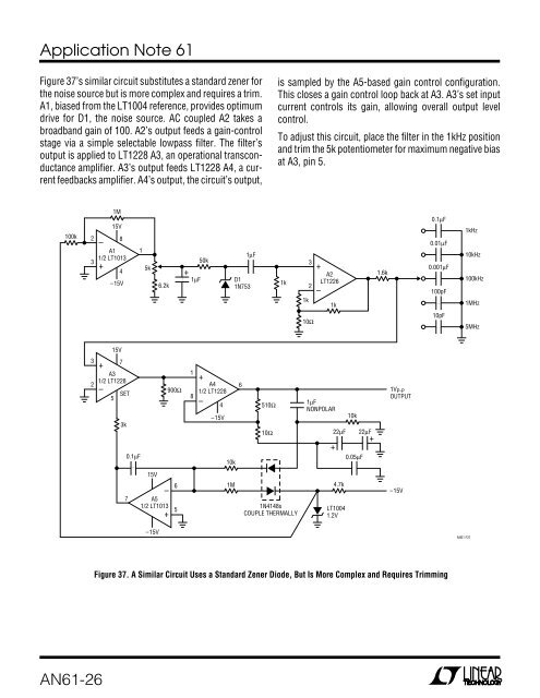
+<strong>Application</strong> <strong>Note</strong> <strong>61</strong>Figure 37’s similar circuit substitutes a standard zener <strong>for</strong>the noise source but is more complex and requires a trim.A1, biased from the LT1004 reference, provides optimumdrive <strong>for</strong> D1, the noise source. AC coupled A2 takes abroadband gain of 100. A2’s output feeds a gain-controlstage via a simple selectable lowpass filter. The filter’soutput is applied to LT1228 A3, an operational transconductanceamplifier. A3’s output feeds LT1228 A4, a currentfeedbacks amplifier. A4’s output, the circuit’s output,is sampled by the A5-based gain control configuration.This closes a gain control loop back at A3. A3’s set inputcurrent controls its gain, allowing overall output levelcontrol.To adjust this circuit, place the filter in the 1kHz positionand trim the 5k potentiometer <strong>for</strong> maximum negative biasat A3, pin 5.100k23A11/2 LT1013–+1M15V84–15V15k6.2k1µF50k1µFD11N7531k32–+A2LT122<strong>61</strong>k1k1.6k0.1µF0.01µF0.001µF100pF1kHz10kHz100kHz1MHz10Ω10pF5MHz15V32+A31/2 LT1228–57SET3k0.1µF900Ω18+A41/2 LT1228–4–15V10k6510Ω10Ω1µFNONPOLAR+22µF10k0.05µF22µF+1V P-P OUTPUT15V7–A51/2 LT1013+651M1N4148sCOUPLE THERMALLY4.7kLT10041.2V–15V–15V<strong>AN<strong>61</strong></strong> F37Figure 37. A Similar Circuit Uses a Standard Zener Diode, But Is More Complex and Requires Trimming<strong>AN<strong>61</strong></strong>-26
<strong>Application</strong> <strong>Note</strong> <strong>61</strong>Switchable Output Crystal OscillatorFigure 38’s simple crystal oscillator circuit permits crystalsto be electronically switched by logic commands. Thecircuit is best understood by initially ignoring all crystals.Further, assume all diodes are shorts and their associated1k resistors open. The resistors at the LT1116’s positiveinput set a DC bias point. The 2k-25pF path sets up phaseshifted feedback and the circuit looks like a wideband unitygain follower at DC. When “Xtal A” is inserted (remember,D1 is temporarily shorted) positive feedback occurs andoscillation commences at the crystals resonant frequency.If D1 and its associated 1k value are realized, oscillationcan only continue if logic input A is biased high. Similarly,additional crystal-diode-1k branches permit logic selectionof crystal frequency.For AT cut crystals about a millisecond is required <strong>for</strong> thecircuit output to stabilize due to the high Q factors involved.Crystal frequencies can be as high as 16MHzbe<strong>for</strong>e comparator delays preclude reliable operation.XTAL XXTAL BDXRX1kBLOGIC INPUTSAS MANY STAGESAS DESIRED5VXTAL AD21kA1k+5VD11k–LT11162kOUTPUT= 1N4148GROUND CRYSTAL CASES25pF<strong>AN<strong>61</strong></strong> • F38Figure 38. Switchable Output Crystal Oscillator. Biasing A or BHigh Places the Associated Crystal in the Feedback Path.Additional Crystal Branches Are PermissibleREFERENCES1. Williams, Jim and Huffman, Brian. “Some Thoughtson DC-DC Converters,” pages 13-17, “1.5V to 5VConverters.” Linear Technology Corporation, <strong>Application</strong><strong>Note</strong> 29, October 1988.2. Williams, J., “Illumination <strong>Circuitry</strong> <strong>for</strong> Liquid CrystalDisplays,” Linear Technology Corporation, <strong>Application</strong><strong>Note</strong> 49, <strong>August</strong> 1992.3. Williams, J., “Techniques <strong>for</strong> 92% Efficient LCD Illumination,”Linear Technology Corporation, <strong>Application</strong><strong>Note</strong> 55, <strong>August</strong> 1993.4. Williams, J., “Measurement and Control Circuit Collection,”Linear Technology Corporation, <strong>Application</strong><strong>Note</strong> 45, June 1991.5. Benjaminson, Albert, “The Linear Quartz Thermometer––aNew Tool <strong>for</strong> Measuring Absolute and DifferenceTemperatures,” Hewlett-Packard Journal, March1965.6. Micro Crystal-ETA Fabriques d’Ebauches., “MiniatureQuartz Resonators - MT Series” Data Sheet. 2540Grenchen, Switzerland.<strong>AN<strong>61</strong></strong>-27