AN61-1 Application Note 61 August 1994 Practical Circuitry for ...
AN61-1 Application Note 61 August 1994 Practical Circuitry for ...
AN61-1 Application Note 61 August 1994 Practical Circuitry for ...

Create successful ePaper yourself
Turn your PDF publications into a flip-book with our unique Google optimized e-Paper software.
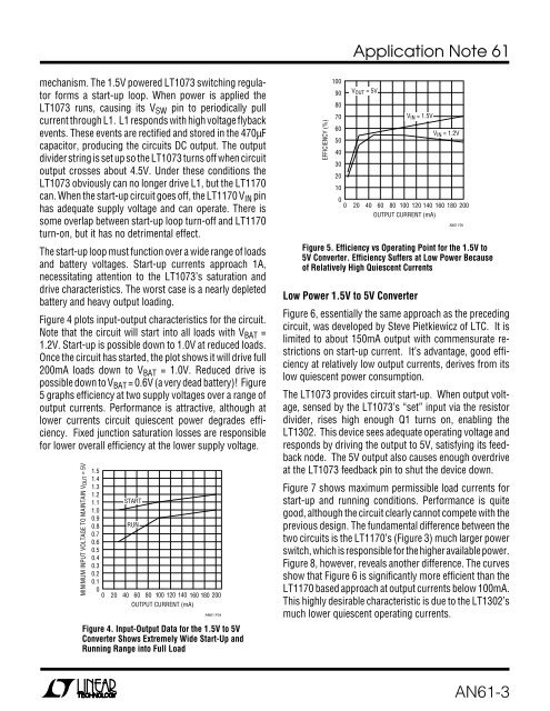
<strong>Application</strong> <strong>Note</strong> <strong>61</strong>mechanism. The 1.5V powered LT1073 switching regulator<strong>for</strong>ms a start-up loop. When power is applied theLT1073 runs, causing its V SW pin to periodically pullcurrent through L1. L1 responds with high voltage flybackevents. These events are rectified and stored in the 470µFcapacitor, producing the circuits DC output. The outputdivider string is set up so the LT1073 turns off when circuitoutput crosses about 4.5V. Under these conditions theLT1073 obviously can no longer drive L1, but the LT1170can. When the start-up circuit goes off, the LT1170 V IN pinhas adequate supply voltage and can operate. There issome overlap between start-up loop turn-off and LT1170turn-on, but it has no detrimental effect.The start-up loop must function over a wide range of loadsand battery voltages. Start-up currents approach 1A,necessitating attention to the LT1073’s saturation anddrive characteristics. The worst case is a nearly depletedbattery and heavy output loading.Figure 4 plots input-output characteristics <strong>for</strong> the circuit.<strong>Note</strong> that the circuit will start into all loads with V BAT =1.2V. Start-up is possible down to 1.0V at reduced loads.Once the circuit has started, the plot shows it will drive full200mA loads down to V BAT = 1.0V. Reduced drive ispossible down to V BAT = 0.6V (a very dead battery)! Figure5 graphs efficiency at two supply voltages over a range ofoutput currents. Per<strong>for</strong>mance is attractive, although atlower currents circuit quiescent power degrades efficiency.Fixed junction saturation losses are responsible<strong>for</strong> lower overall efficiency at the lower supply voltage.MINIMUM INPUT VOLTAGE TO MAINTAIN V OUT = 5V1.51.41.31.21.11.00.90.80.70.60.50.40.30.20.100STARTRUN20 40 60 80 100 120 140 160 180 200OUTPUT CURRENT (mA)<strong>AN<strong>61</strong></strong> F04Figure 4. Input-Output Data <strong>for</strong> the 1.5V to 5VConverter Shows Extremely Wide Start-Up andRunning Range into Full LoadEFFICIENCY (%)100908070605040302010V OUT = 5VV IN = 1.5VV IN = 1.2V00 20 40 60 80 100 120 140 160 180 200OUTPUT CURRENT (mA)<strong>AN<strong>61</strong></strong> F05Figure 5. Efficiency vs Operating Point <strong>for</strong> the 1.5V to5V Converter. Efficiency Suffers at Low Power Becauseof Relatively High Quiescent CurrentsLow Power 1.5V to 5V ConverterFigure 6, essentially the same approach as the precedingcircuit, was developed by Steve Pietkiewicz of LTC. It islimited to about 150mA output with commensurate restrictionson start-up current. It’s advantage, good efficiencyat relatively low output currents, derives from itslow quiescent power consumption.The LT1073 provides circuit start-up. When output voltage,sensed by the LT1073’s “set” input via the resistordivider, rises high enough Q1 turns on, enabling theLT1302. This device sees adequate operating voltage andresponds by driving the output to 5V, satisfying its feedbacknode. The 5V output also causes enough overdriveat the LT1073 feedback pin to shut the device down.Figure 7 shows maximum permissible load currents <strong>for</strong>start-up and running conditions. Per<strong>for</strong>mance is quitegood, although the circuit clearly cannot compete with theprevious design. The fundamental difference between thetwo circuits is the LT1170’s (Figure 3) much larger powerswitch, which is responsible <strong>for</strong> the higher available power.Figure 8, however, reveals another difference. The curvesshow that Figure 6 is significantly more efficient than theLT1170 based approach at output currents below 100mA.This highly desirable characteristic is due to the LT1302’smuch lower quiescent operating currents.<strong>AN<strong>61</strong></strong>-3