Snapper Lawn Tractor Hydrostatic Drive Electric Clutch Series G ...
Snapper Lawn Tractor Hydrostatic Drive Electric Clutch Series G ...
Snapper Lawn Tractor Hydrostatic Drive Electric Clutch Series G ...

Create successful ePaper yourself
Turn your PDF publications into a flip-book with our unique Google optimized e-Paper software.
Section 2 - OPERATING INSTRUCTIONS2.1 PRE-START CHECKLISTMake the following checks and perform service asrequired before each start-up.2.1.1. Check tires and add air as needed to bringpressure to 12 P.S.I. in front tires and 12 P.S.I. inrear tires.FUEL TANK2.1.2. Check guards, deflectors and covers to makesure all are in place and securely tightened. If guardsare missing or damaged, replace BEFORE usingmower.2.1.3. Check engine oil and add oil as needed tobring level up to, but not over, the FULL mark. Refer toengine owner’s manual for oil specifications. See Figure2.1.TIGHTEN CAPAFTERFILLING TANKSAFELEVELAREAFIGURE 2.2FIGURE 2.12.1.4. Check blade switch to ensure it movesfreely. Manually pull switch out to the “ON” positionand push switch down to the “OFF” position.2.1.5. Clean exterior surfaces of cutting deck, engineand tractor of any accumulation of dirt, grass, oil, etc.Keep engine air intake screens and cooling fins clean atall times.2.2 OPERATOR’S SEAT ADJUSTMENT2.2.1. FRONT TO REAR ADJUSTMENT1. With the engine "OFF", raise operator's seat andloosen the two adjusting knobs on the seat support.Lower the seat. Sit in the operator's seat and slide theseat forward or backward until the clutch/brake pedalcan be fully depressed comfortably. Raise seat andtighten the adjusting knobs to secure seat in position.See Figure 2.3.LOOSEN ADJUSTINGKNOBS TO ADJUSTSEAT2.1.6. With engine “OFF” move the tractor outsideand add fuel to the fuel tank. Securely tighten fuel capafter refueling. Refer to engine owner’s manual for fuelspecifications. See Figure 2.2.2.1.7. Check Reverse Lockout Mechanism. Refer toSection “Reverse Lockout Mechanism”.FIGURE 2.36
Section 2 - OPERATING INSTRUCTIONS2.3 STARTING & OPERATION2.3.1. STARTING ENGINE1. Take a comfortable position in seat of machine,look around to make sure that the area you are going tomow is clear of people, children and pets. Take note ofany stationary obstacles!NOTE: The interlock system will prevent the engine fromstarting if the blade switch is in the "ON" (up) position or ifthe clutch/brake pedal is not fully depressed. If the interlocksystem ever fails to work, DO NOT OPERATE the tractoruntil the interlock has been repaired.2. Push blade switch down to the "OFF" position. SeeFigure 2.4. PUSH BLADE SWITCH “DOWN” TOSTART MACHINEBLADESWITCH5. Choke engine for cold starting by moving enginespeed control to "CHOKE" position. NOTE: Somemodels are equipped with a separate choke control,located on the dash of the tractor. Pull the control“OUT” to choke position to start a cold engine. Littleor no choking will be needed when restarting a warmengine. Insert key in switch. Turn key to "START"position to crank engine and hold until engine starts,then release key to “RUN” position. See Figure 2.6.NOTE: DO NOT crank engine for more than fiveseconds at a time. This will help prevent the starter fromoverheating and/or running down the battery. If crankingtime is more than five seconds, locate and correct causeof starting problem.6. After engine starts, release key, move the enginespeed control to "FAST" position and allow engine towarm up before proceeding. See Figure 2.6.CHOKEPOSITIONLIGHTSWITCHOFFFASTFIGURE 2.4SLOW3. Depress the clutch/brake pedal fully. See Figure 2.5.4. Move speed control lever to neutral.NOTE: The seat interlock will shut off the engine if theoperator gets off the seat without setting the parkingbrake or if the blades are running. If the interlock everfails to work, DO NOT OPERATE the tractor until theinterlock has been repaired.CLUTCH/BRAKEPEDALENGINESPEEDCONTROLFIGURE 2.6KEYPARKBRAKELEVERDOWNWARNINGDO NOT leave machine with engine running. Stopengine. Stop blades. Set parking brake. Remove key.FIGURE 2.5PUSH PEDAL ALL THEWAY DOWN TO STARTENGINE7
Section 2 - OPERATING INSTRUCTIONS2.3 STARTING & OPERATION (Continued)2.3.2. STARTING WHEEL DRIVE1. Shift speed control lever to neutral.2. Start engine. Refer to Section “STARTINGENGINE”.3. Release clutch/brake pedal.4. Slowly shift speed control lever forward forforward motion or to the rear for reverse motion. SeeFigure 2.7.SPEED CONTROL LEVER2.4 STOPPING ENGINE, BLADE, WHEEL DRIVE2.4.1. STOPPING ENGINE1. Stop engine by turning key to the "OFF" position.See Figure 2.9.OFFRUNSTARTNEUTRALREVERSEKEYFORWARDSPEEDSFIGURE 2.7FIGURE 2.92.4.2. STOPPING WHEEL DRIVE1. Fully depress clutch/brake pedal to stop wheeldrive. See Figure 2.10.2.3.3 STARTING MOWER BLADE1. Start engine. Refer to Section “STARTINGENGINE”.2. Pull blade switch OUT to engage blade. SeeFigure 2.8.PUSH BLADE SWITCH IN TOTHE “OFF” POSITIONONCLUTCH/BRAKEPEDALOFFPULL BLADESWITCH OUT TOTHE “ON”POSITIONFULLY DEPRESSCLUTCH/BRAKE PEDAL TOSTOP WHEEL MOTIONFIGURE 2.10FIGURE 2.8WARNINGDO NOT operate blades in reverse. STOP BLADES.LOOK and SEE behind and down for children, petsand hazards before and while backing.8
Section 2 - OPERATING INSTRUCTIONS2.4 STOPPING2.4.3. STOPPING MOWER BLADES1. Stop mower blade by pushing blades switch IN todisengage blades. See Figure 2.11.2.4.5. RELEASING PARK BRAKE1. Fully depress clutch/brake pedal. Move park brakelever “DOWN” to release park brake. Releaseclutch/brake pedal. See Figure 2.13.PUSH BLADE SWITCH IN TOTHE “OFF” POSITIONONCLUTCH/BRAKEPEDALPARKBRAKELEVEROFFPULL BLADESWITCH OUT TOTHE “ON”POSITIONFULLY DEPRESSCLUTCH/BRAKEPEDALFIGURE 2.11WARNINGOnce blades are disengaged, they should come to acomplete stop in 5 seconds or less. If the bladescontinue to rotate after 5 seconds, the blade brakemust be repaired. Return machine to an authorizedSNAPPER dealer. DO NOT continue to operatemachine until blade brake has been repaired andfunctioning properly.2.4.4. SETTING PARK BRAKE1. Fully depress clutch/brake pedal.2. Move park brake lever up into slot. See Figure 2.12.3. Release pedal.FIGURE 2.132.5. CUTTING HEIGHT ADJUSTMENT1. Depress lock button on cutting height adjustmentlever. See Figure 2.14.DEPRESSLOCK BUTTONCUTTINGHEIGHTADJUSTMENTLEVERPUSH PEDAL ALLTHE WAY DOWNPARK BRAKELEVERHIGHEST CUTFIGURE 2.14LOWEST CUT2. Raise or lower deck to any of six positions asdesired. Release lock button.MOVE PARK BRAKELEVER “UP” TOENGAGE PARK BRAKEWARNINGDO NOT park machine on slopes.FIGURE 2.129
Section 2 - OPERATING INSTRUCTIONS2.7. REVERSE LOCKOUT MECHANISMData indicates that tragic back-over accidents occureach year. These accidents usually involve unsupervisedchildren. Many times these children have been givenrides on the machine and have been trained to view thispotentially dangerous piece of machinery as fun ratherthan being taught how to avoid danger.This riding mower has a Reverse Lockout Mechanism.This mechanism prevents the mower from being shiftedinto reverse with the blades running. To shift into reverseyou must first stop the blades and then shift to reverse. Itis our recommendation that this mechanism remainfunctional and the operator of this equipment develop thehabit of never backing up with the blades running. As theSafety Instructions Indicate, DO NOT operate blades inreverse. STOP BLADES, LOOK AND SEE BEHINDAND DOWN for children, pets and hazards beforeand while backing.We realize that this could cause a change to yourprevious mowing method but we encourage you to adjustto this new system. Do not defeat the Reverse LockoutMechanism.If you operate your mower near roadways or useattachments that require quicker shifting to reverse,there is an override lever provided. This lever can bepushed and held before engaging the blades and willallow reverse operation until the blade switch is pushedin to the “OFF” position, at which time the system willreturn to its Reverse Lockout mode. This feature shouldnever be selected unless you are absolutely sure that nochildren or others are present in the mowing area andthat all children are away and supervised by aresponsible adult.2.7.1. Reverse Lockout Mechanism Override1. Stop machine. Stop blades.2. Depress and hold Override Lever.3. Pull blade switch “OUT” to engage blade.4. Release Override LeverWARNINGLOOK and SEE behind and down for children, petsand hazards before and while backing.IMPORTANT! DO NOT use the Reverse LockoutMechanism Override as the normal operating mode. Toreturn to the Reverse Lockout Mechanism mode,disengage (STOP) blades by pushing blade switch in tothe “OFF” position. The Override will reset to ReverseLockout.2.7.2. Check the Reverse Lockout MechanismBefore each use, check the Reverse LockoutMechanism for proper function. The followingprocedure requires the operation of the engine andblades. Before proceeding, Read, Understand, andFollow all Safety Instructions and Warnings in thismanual and on the machine.1. Complete Pre-Start Checklist.2. Move machine to clear open area. DO NOTallow children or others in area.3. Start engine.4. Pull blade switch “OUT” to engage blades.5. Reverse Lockout Mechanism must preventspeed control lever from going into reverse.WARNINGDO NOT operate machine if Reverse LockoutMechanism is not functioning properly. Contact yourSNAPPER dealer immediately for assistance.11
Section 3 – MAINTENANCE3.1 INTRODUCTIONTo retain the quality of the <strong>Tractor</strong>, use genuineSNAPPER replacement parts only. Contact a localSNAPPER dealer for parts and service assistance. Forthe correct part or information for a particular <strong>Tractor</strong>,always mention the model and serial number. SNAPPERrecommends returning the <strong>Tractor</strong> to an authorizedSNAPPER dealer annually for inspection and additionof any new devices, which might upgrade the safety ofthe <strong>Tractor</strong>. For the nearest SNAPPER dealer in yourarea, check the yellow pages under the heading LAWNMOWERS. For engine parts and service, look for theengine manufacturer’s dealers under the heading,ENGINES - gasoline.4. Check blade for straightness. Refer to Section“ADJUSTING MOWER BLADE”.5. Check torque of blade mounting bolts. Torque to:42" deck - 30 to 40 ft lbs. See Figure 3.2.48" deck - 70 to 80 ft lbs.OILFILLERTUBE3.2 SERVICE - AFTER FIRST 5 HOURSWARNINGDO NOT attempt any adjustments, maintenance or servicewith the engine or blades running. STOP blades. STOPengine. Set brake. Remove key. Remove spark plug wirefrom spark plug and secure wire away from spark plug.Engine and components can be extremely hot. Avoid burnsby allowing engine and components sufficient time to cool.3.2.1. CHANGE ENGINE OILThe engine is equipped with a Fastex oil drain.1. Rotate drain body counterclockwise and pull out toopen drain. See Figure 3.1.2. Drain oil into a 2 quart container placed beneath endof oil drain.3. After all oil has drained, push drain body "IN" androtate clockwise to close.4. Fill engine with new motor oil as specified in engineowner's manual.WARNINGThe following procedure requires the engine and bladesto be operated. Exercise extreme caution. Clear area ofloose parts & tools first. Only operate blades whenseated in the operator’s seat.ROTATE COUNTER-CLOCKWISE AND PULLOUT TO OPEN.PUSH IN AND ROTATECLOCKWISE TO CLOSE.FIGURE 3.1TORQUE TO30 TO 40 FT.LBS.FASTEXOIL DRAIN3.2.2. CHECK BLADE BRAKE1. Check blade brake for proper function. Bladesshould stop rotating in 5 seconds or less after pushing theblade switch “IN” to the OFF disengaged position.2. If blades continue to rotate longer than 5 seconds donot operate machine. Contact your SNAPPER dealer forassistance.3.2.3. CHECK MOWER BLADES1. Remove deck from tractor.2. Carefully position deck to access blade.3. Check blade for sharpness, wear and damage.Refer to Section “BLADE WEAR LIMITS”.FIGURE 3.242” DECK SHOWNWARNINGBlades must stop rotating in 5 seconds or less afterblades have been turned off. DO NOT operate machineuntil blade brake has been repaired and functioningproperly. Contact your SNAPPER dealer for assistance.12
Section 3 - MAINTENANCE3.2.4. CHECK DECK DRIVE BELT1. The idler and spring provide proper belt tension andrequire no adjustment. If belt is frayed, slit, severed orbelt strands exposed, replace belt before operatingmower.3.3 SEVICE - EVERY 25 OPERATING HOURS3.3.1. CHECK ENGINE1. Change engine oil. Refer to Section “CHANGEENGINE OIL”. Refer to engine owner's manual for oilspecification.2. Remove and clean engine air pre-cleaner. SeeFigure 3.4. Refer to engine owner's manual forcleaning instructions.3. Remove and replace engine air cleaner. Refer toengine owner's manual for service instructions.SINGLE CYLINDER ENGINE TYPEAIR CLEANER BASECOVER RETAININGKNOBAIR CLEANER COVERELEMENT RETAINING KNOBCARTRIDGE ELEMENTPRE-CLEANERRETAINING STUDAIR CLEANER BASE3.3.2. MOWER COMPONENTS1. Check deck drive belt for proper tension. Referto Section, “CHECK DECK DRIVE BELT”.2. Check blades for sharpness, wear, damage andtorque. Refer to Section on “MOWER BLADESERVICE”.3. Check mower deck for proper levelness. Referto Section “MOWER DECK ADJUSTMENT -LEVELNESS”.4. Clean mower deck.a. Remove key from ignition switch.b. Remove deck.c. Clean underside of mower deck, removing allaccumulation of grass clippings and debris.d. Clean top of deck, removing all grass clippingsand debris.5. Lubricate spindles with 1 to 3 shots of generalpurpose grease from grease gun.IMPORTANT - 48” DECK ONLY:Spindles on 48” deck must be kept filled withgrease. Apply grease from grease gun untilgrease purges from vent located underneathdeck on spindle housing.6. Lubricate all mower deck linkage pivot pointswith a light coat of motor oil.3.3.3. CHECK BLADE BRAKE1. Refer to Section “CHECK BLADE BRAKE”.3.3.4. TRACTOR LUBRICATION1. Front Wheel BearingsLubricate each front wheel bearing through thegrease fitting on wheel hub. Using general purposegrease in a grease gun, add grease until greasepurges from bearing. See Figure 3.5.CARTRIDGE ELEMENTPRE-CLEANERRETAINING KNOBRETAINING PLATEAXLE SPINDLELUBRICATIONFITTINGAIR CLEANER COVERTWIN CYLINDER ENGINE TYPEFIGURE 3.4COVER RETAINING CLIPSFRONT WHEELBEARING LUBRICATIONFITTINGFIGURE 3.52. Axle SpindlesLubricate each axle spindle with 1 to 3 shots ofgeneral purpose grease. See Figure 3.5.(Continued On Next Page)13
Section 3 - MAINTENANCE3.3.4. TRACTOR LUBRICATION(Continued From Previous Page)3. <strong>Clutch</strong>/Brake PivotThe clutch/brake pivot is located on the L.H.underside of the tractor and is lubricated with oneshot of general purpose grease. See Figure 3.6.DRAG LINKLUBRICATIONPOINTCLUTCH/BRAKEPIVOT LUBRICATIONFITTINGFIGURE 3.87. Steering Tie RodLubricate both ends of steering tie rod with a smallamount of 30 wt. motor oil from an oil can. SeeFigure 3.9.LUBRICATEBOTH ENDSOF TIE RODFIGURE 3.64. Steering Sector GearLubricate with a light coat of general purpose grease.See Figure 3.7.LUBRICATESTEERINGSECTOR GEARFIGURE 3.98. Park Brake LeverUsing 30 wt. motor oil, lubricate the park brake levermechanism pivot points, which are located on the lefthand underside of tractor. See Figure 3.10. Lubricatemechanism with a thin coat of 30 wt. motor oil.LUBRICATESTEERINGSHAFT GEARPARK BRAKELEVERFIGURE 3.75. Steering ShaftLubricate steering shaft wear points with a light coatof 30 wt. Motor oil.6. Steering Drag LinkLubricate both ends of steering drag link with a smallamount of 30 wt. motor oil from an oil can. SeeFigure 3.8.LUBRICATECOMPONENTS ONUNDERSIDE OFTRACTORFIGURE 3.109. Deck Lift MechanismLubricate all wear and pivot points of the deck lift.14
Section 3 - MAINTENANCE3.4 ANNUALLY (END OF EACH SEASON)Perform all maintenance as described in Section“SERVICE - EVERY 25 OPERATING HOURS”. Alsosee Service Schedule.3.4.1. ENGINE1. Service engine according to engine owner'smanual.3.4.2. FUEL FILTER1. Service fuel filter as instructed below, on COLDENGINE ONLY!NOTE: It may be necessary to drain the fuel tank beforeremoving fuel filter to prevent spillage of gasoline.2. Locate fuel filter. Remove hose clamps and fuelhoses from both sides of fuel filter.3. Install new fuel filter part number 1-4359. SeeFigure 3.11.NEW FUEL FILTERPART NUMBER 1-4359FIGURE 3.114. Fill fuel tank with fresh gasoline. Refer to engineowner's manual for fuel specifications.3.4.3. SPARK PLUGRemove and replace engine spark plug. Refer toengine owner's manual for correct replacement plugand gap specifications.3.4.4. HYDROSTATIC TRANSMISSION OILThe hydrostatic transmission does not requiremaintenance. If any problems arise returnimmediately to a <strong>Snapper</strong> dealer.15
Section 4 - ADJUSTMENT & REPAIRWARNINGDO NOT attempt any adjustments, maintenance orservice with the engine or blades running. STOPblades. STOP engine. Set brake. Remove key.Remove spark plug wire from spark plug and securewire away from spark plug. Engine and componentscan be extremely hot. Avoid burns by allowing engineand components sufficient time to cool.4.1 ENGINE ADJUSTMENTS & REPAIRRefer to the engine owner's manual for thoseadjustments and/or repairs that can be made by theowner.4.2 MOWER DECK & COMPONENT ADJUSTMENTSThe following mower deck and component adjustmentsand repairs can be made by the owner. However, if thereis difficulty in achieving these adjustments and repairs, itis recommended that these repairs be made by anauthorized SNAPPER dealer.WARNINGBlades must stop rotating in 5 seconds or less afterblades have been turned off. DO NOT operatemachine until blade brake has been repaired andfunctioning properly. Contact your SNAPPER dealerfor assistance.4.2.1. BLADE BRAKE ADJUSTMENTThe blade brake when functioning properly will stopblade rotation in 5 seconds or less. The brake requiresno adjustment. If blades continue to rotate after 5seconds the blade brake must be repaired. Contact yourauthorized SNAPPER dealer for assistance.Xd. Disconnect rear sector plates and allow center,rear of deck to rest on angle iron.e. Measure the distance from blade tips to floor. Ifthe measurement is within 1/8” from side-to-side, thedeck levelness is satisfactory. If the difference fromside-to-side is greater than 1/8”, an adjustment willhave to be made. See Figure 4.1.REAR TO FRONT VIEW OF DECKFIGURE 4.1ANGLE IRONX - 1/8”f. Loosen the shoulder bolt that retains theeccentric.g. Turn eccentric “UP” or “DOWN” as requireduntil blade tips are within 1/8” of the samedistance from the floor. See Figure 4.2.h. Tighten shoulder bolt loosened in Step “f”.i. Readjust rear sector plates to align with holesin support brackets.j. Reconnect sector plates, remove angle iron,pipe, etc. and recheck side to side level. Adjust asneeded to result in blade tips being within 1/8” of thesame distance from the floor.k. Proceed to check front to rear deck pitch.4.2.2. BLADE BELT ADJUSTMENTThe 42” and 48” mower deck drive belts do notrequire any adjustment. If the belt does not driveblade properly, replace belt as needed.LOOSENSHOULDERBOLTLOOSENPIVOTBOLT4.2.3. MOWER DECK ADJUSTMENT (LEVELNESS)1. SIDE-To-SIDE (42” Decks)Before making deck leveling adjustments, check thetire pressure. Check tires and add or release air asneeded to bring pressure to 12 PSI in front and 12 PSIin rear tires. If tires are properly inflated and mowingis still uneven, adjust side-to-side deck levelness asfollows:a. Place machine on a smooth level surface.b. Turn engine off and remove key, remove sparkplug wire(s) from spark plug(s) and secure wire(s)away from plug(s).c. Place a piece of angle iron, pipe, or similarobject under center of deck at the rear.FIGURE 4.2TURN ECCENTRICAS REQUIRED16
Section 4 – ADJUSTMENT & REPAIRWARNINGDO NOT attempt any adjustments, maintenance orservice with the engine or blades running. STOPblades. STOP engine. Set brake. Remove key.Remove spark plug wire from spark plug and securewire away from spark plug. Engine and componentscan be extremely hot. Avoid burns by allowing engineand components sufficient time to cool.4.2.4. MOWER DECK ADJUSTMENT (LEVELNESS)FRONT-To-REAR (42” Decks)1. Remove hair pins and washers securing sectorplates to rear lift arms. See Figure 4.3.SECTOR PLATESHAIR PINWASHERJAM NUTCLEVISPINFRONT LIFT CABLEFRONT LIFT RODHANGERFRONT LIFT RODFIGURE 4.4HIGHEST DECKSETTINGFIGURE 4.3LOWEST DECKSETTINGREMOVE HAIR PIN& WASHER2. Move sector plate as required to raise or lower therear of deck.9. Remove front lift cable and rest front of deck onto2 x 4 block.10. Loosen jam nut on front lift cable. See Figure 4.4.11. Rotate front lift cable until it can be reinstalled intofront lift arm without lifting deck.12. Secure lift cable to lift arm with washer and hair pin.Secure jam nut.13. Reinstall sector plates onto rear hanger bracketsand secure with washers and hair pins.14. Raise deck and remove wooden blocks.15. Repeat steps for front to rear level until levelness isacquired.NOTE: The deck should be set so that the rear of the deckis 1/4” lower than the front.3. If the sector plates are in their lowest setting andproper level cannot be obtained, adjust the front lift rodas follows:4. Move deck lift lever to #5 position.5. Place a 2 x 4 wooden block on edge under frontcenter of deck.6. Place a 3 x 3 wooden block under rear center ofdeck.7. Remove hair pins and washers securing sectorplates. Lower rear of deck onto 3 x 3 block.8. Remove hair pin and washer securing front liftcable to front lift arm. See Figure 4.4.17
Section 4 - ADJUSTMENT & REPAIR4.2.5. MOWER DECK ADJUSTMENT (LEVELNESS)SIDE-To-SIDE (48” Decks)Before making deck leveling adjustments, check thetire pressure. Check tires and add or release air asneeded to bring pressure to 12 PSI in front and 12PSI in rear tires. If tires are properly inflated andmowing is still uneven, adjust side-to-side decklevelness as follows:1. Place machine on a smooth level surface.2. Rotate outside blades so tips are pointed to thesides of deck. See Figure 4.5. Measure thedistance from blade tips to floor. If themeasurement is within 1/8” from side-to-side, thedeck levelness is satisfactory. If the differencefrom side-to-side is greater than 1/8”, continue tonext step for adjustment.3. Place a 2 x 4 piece of wood under the frontmiddle portion of deck. Place one 2 x 4 piece ofwood under the rear of deck on both sides behindthe two outside blades. See Figure 4.5.4. Lower deck down to rest on the three 2 x 4 piecesof wood. Make sure there is no deck tension onthe lift rods supporting the deck.5. Loosen the bolt and nut that secures the front lift armweldment to the front lift arm. See Figure 4.6.FRONT LIFTARMPLACE THREE 2 X 4 UNDERFRONT AND REAR OF DECKFIGURE 4.5TOP VIEW OF DECKFRONT LIFT ARMWELDMENTLOOSENNUTTOP VIEW OF DECKFIGURE 4.6(Continued On Next Page)18
Section 4 - ADJUSTMENT & REPAIRWARNINGDO NOT attempt any adjustments, maintenance orservice with the engine or blades running. STOPblades. STOP engine. Set brake. Remove key.Remove spark plug wire from spark plug and securewire away from spark plug. Engine and componentscan be extremely hot. Avoid burns by allowing engineand components sufficient time to cool.4.2.5. MOWER DECK ADJUSTMENT (LEVELNESS)SIDE-To-SIDE (48” Decks)(Continued From Previous Page)6. Remove both hair pins and washers from swivellocated on rear lift rods and pull rod out of deckbrackets.7. Rotate swivels on both sides up or down toachieve the proper levelness. See Figure 4.7.8. Reinstall swivel into deck bracket. Reinstallwashers and hair pins.9. Tighten nut and bolt on front lift arm securely.4.2.6. MOWER DECK ADJUSTMENT (LEVELNESS)(FRONT To REAR)Before making deck leveling adjustments, check thetire pressure. Add or release air as needed to bringpressure to 12 PSI in front and 12 PSI in rear tires. Iftires are properly inflated and mowing is still uneven,check side-to-side deck levelness first then proceedto front to rear adjustment. Adjust front to rear decklevelness as follows:1. Place machine on a smooth level surface.2. Rotate outside blades so tips are pointed to thefront and rear of deck. Measure the distance fromblade tips to floor. The distance should be the same, orthe rear no more than 1/4” higher than the front. If therear blade tip is lower or is more than 1/4” higher thanthe front, proceed to next Step for adjustment.3. Remove the hair pin & washer from swivel locatedon lift rod. Remove swivel/lift rod from hanger bracket.4. Rotate swivel up or down to achieve the properlevelness.5. Reinstall swivel/lift rod into hanger bracket. Reinstallwasher & hair pin to secure swivel to hanger bracket.See Figure 4.7.REAR LIFT RODREMOVE WASHER & HAIR PIN& ROTATE SWIVEL UP OR DOWNFRONTLIFTRODSWIVELDECKBRACKETSWIVELREMOVE WASHER & HAIR PIN& ROTATE SWIVEL UP OR DOWNFIGURE 4.719
Section 4 - ADJUSTMENT & REPAIRWARNINGDO NOT attempt any adjustments, maintenance orservice with the engine or blades running. STOPblades. STOP engine. Set brake. Remove key.Remove spark plug wire from spark plug and securewire away from spark plug. Engine and componentscan be extremely hot. Avoid burns by allowing engineand components sufficient time to cool.4.3 TRACTOR DRIVE COMPONENTS4.3.1. BRAKE ADJUSTMENTWhen adjusted properly, the brake should stop thetractor in approximately 6 feet or less from top speed.<strong>Drive</strong> the machine at maximum forward speed andapply the brake. If stopping distance is greater than 6feet, brake adjustment is required.1. Turn engine “OFF”. Remove key.2. Locate brake adjustment nut underneath the left sideat the rear of tractor. See Figure 4.8.3. Turn nut 1 turn clockwise to increase brakingaction. DO NOT over tighten brake adjustment.4. Start engine and test brake.5. Continue adjustment as described above untilproper brake function is achieved.ROTATE ADJUSTING NUTCLOCKWISE TO INCREASEBRAKING OR COUNTERCLOCKWISE TO DECREASEBRAKINGROTATE TOREDUCE “PLAY”FIGURE 4.9FUEL TANKECCENTRICMOUNTING NUT3. Loosen the eccentric mounting nut and rotate theeccentric clockwise until steering “Play” is reduced.See Figure 4.9.4. Tighten eccentric mounting nut.4.3.3. SHIFTER ADJUSTMENTThe shift linkage is set at the factory and should notrequire further adjustment. The shifter is adjustedproperly when the speed control lever can be placedat rear edge of the neutral detent and the tractorremains absolutely stationary. If motion is detected,neutral adjustment will be required. DO NOT operatea machine that creeps when shifted to neutral.1. Stop engine. Remove key.2. Move speed control lever to rear edge of neutraldetent and hold firmly.3. Locate neutral adjustment nut underneath theright rear of the tractor. See Figure 4.10NEUTRALADJUSTMENTNUTFIGURE 4.84.3.2. STEERING ADJUSTMENTShould excessive “Play” be noted in the steering,adjust as follows:1. Turn engine “OFF”. Remove key.2. From left side of tractor, locate the steering sectorbelow fuel tank. See Figure 4.9.TURN NUT CLOCKWISE TOREDUCE FORWARD CREEPFIGURE 4.1020
Section 4 - ADJUSTMENT & REPAIRWARNINGDO NOT attempt any adjustments, maintenance orservice with the engine or blades running. STOPblades. STOP engine. Set brake. Remove key.Remove spark plug wire from spark plug and securewire away from spark plug. Engine and componentscan be extremely hot. Avoid burns by allowing engineand components sufficient time to cool. Wear heavyleather gloves when handling or working aroundcutting blades. Blades are extremely sharp and cancause severe injury.4.3.3. SHIFTER ADJUSTMENT(Continued from previous page)4. Turn the neutral adjustment nut 1/4 turn clockwiseto reduce FORWARD creep. Turn the adjustment nut1/4 turn counter clockwise to reduce Reverse creep.Only turn the adjustment nut in 1/4 turn increments.5. Check for creep in neutral. Start engine. Movespeed control lever to rear edge of the neutral detent.Machine should not move. If further adjustment isrequired, stop engine and repeat Step 4.BELT GUIDESTATIONARY IDLERSTATIONARY IDLERMOUNTING BOLTMORE TENSIONLESS TENSIONMOUNTINGBRACKETMORE TENSIONLESS TENSIONMOUNTING BRACKETBELT GUIDE - MAKE CERTAINBELT GUIDE ORIENTATION ISMAINTAINED.STATIONARY IDLER4.3.4. TRACTION DRIVE BELT ADJUSTMENTShould a gradual loss of traction be noticed, it may benecessary to adjust the traction drive belt tension. Adjustas follows:1. Move tractor to a firm, level surface.2. Turn engine "OFF". Remove key.3. Remove mowing deck.4. Remove the traction drive belt stationary idlermounting bolt. See Figure 4.11.5. Move the stationary idler one hole towards right sideof tractor for more belt tension.MOUNTING BRACKETFIGURE 4.114.4 MOWER BLADE SERVICE4.4.1. (STANDARD) BLADE WEAR LIMITSAll mower blades should be checked for excessive wearand damage before each use. See Figure 4.12.NOTE: Note the orientation of belt guide and make certain itremains in the same orientation after moving idler. Shouldless tension be required move stationary idler towards rightside of tractor. See Figure 4.11.6. Secure stationary idler with mounting bolt.7. Place spark plug wire onto spark plug. Set parkbrake. Start engine.8. Visually inspect traction drive belt for movement.When properly adjusted, the traction drive belt should nothave any movement or rotation with the engine runningand park brake engaged.9. Should movement be present, readjust traction drivebelt to release belt tension as described in previousinstructions.NOTCH FORMINGFIGURE 4.12NEWBLADEWEAR LIMIT.CUTTING EDGEWORN.DANGEROUS CONDITION! DONOT USE ON MOWER!21
Section 4 - ADJUSTMENT & REPAIRWARNINGDO NOT attempt any adjustments, maintenance orservice with the engine or blades running. STOPblades. STOP engine. Set brake. Remove key.Remove spark plug wire from spark plug and securewire away from spark plug. Engine and componentscan be extremely hot. Avoid burns by allowing engineand components sufficient time to cool. Wear heavyleather gloves when handling or working aroundcutting blades. Blades are extremely sharp and cancause severe injury.STANDARD BLADE22º TO 28ºORIGINAL CUTTING EDGEFIGURE 4.144.4.2. (NINJA) BLADE WEAR LIMITSThe ninja recycling blade requires more frequent serviceintervals than standard blades. Check for excessive wearand damage before each use. See Figure 4.13.NEWBLADEWEAR LIMIT. (CRACKSOR NOTCHES BEGINTO APPEAR)4.4.4. (NINJA) BLADE SHARPENINGThe Ninja recycling blades requires more frequentservice intervals than standard blades. When theblades are dull, cut grass will be ragged and lawn willusually turn brown. Sharpen standard blades asfollows:1. Move tractor to a firm, level surface.2. Turn engine "OFF". Remove key.3. Remove mowing deck from tractor.4. Remove mower blade(s).5. Sharpen all cutting edges of the Ninja recyclingblade at an angle of 22 to 28 degrees for optimumperformance. See Figure 4.15.NINJA BLADEDANGEROUS CONDITION!DO NOT USE ON MOWER!FIGURE 4.134.4.3. (STANDARD) BLADE SHARPENINGBlades should be kept sharp at all times. When theblades are dull, cut grass will be ragged and lawn willusually turn brown. Sharpen standard blades asfollows:1. Move tractor to a firm, level surface.2. Turn engine "OFF". Remove key.3. Remove mowing deck from tractor.4. Remove mower blade(s).5. If a blade is in good condition, sharpen cuttingedge at an angle of 22 to 28 degrees. DO NOTsharpen beyond existing cutting edge. Replace bladesnot in good condition. See Figure 4.14.FIGURE 4.1522º TO 28ºBLADE TIP22
Section 4 - ADJUSTMENT & REPAIRWARNINGDO NOT attempt any adjustments, maintenance orservice with the engine or blades running. STOPblades. STOP engine. Set brake. Remove key.Remove spark plug wire from spark plug and securewire away from spark plug. Engine and componentscan be extremely hot. Avoid burns by allowing engineand components sufficient time to cool. Wear heavyleather gloves when handling or working aroundcutting blades. Blades are extremely sharp and cancause severe injury.SPINDLE WASHERDECK/DRIVEPULLEYSPINDLEHOUSINGASSEMBLY4.4.5. 42" MOWER BLADE REPLACEMENT1. Move tractor to a firm, level surface.2. Turn engine "OFF". Remove key.3. Remove mowing deck from tractor.4. Position deck on its left side to access blade.5. Remove blade mounting bolts and cone washers.See Figure 4.16.SPINDLE COVER CUPBLADECONEWASHERSPINDLEASSEMBLYBLADEBARMOUNTINGBOLTBLADEFIGURE 4.17CONEWASHERBLADEMOUNTINGBOLT6. Install new blade.7. Torque 30 to 40 ft lbs.FIGURE 4.164.4.6. 48" MOWER BLADE REPLACEMENT1. Move tractor to a firm, level surface.2. Turn engine "OFF". Remove key.3. Remove mowing deck from tractor.4. Position deck to access blade.5. Remove blade mounting nut and cone washer fromeach blade. See Figure 4.17.6. Install new blades.7. Torque 70 to 80 ft lbs.23
Section 4 - ADJUSTMENT & REPAIRWARNINGDO NOT attempt any adjustments, maintenance orservice with the engine or blades running. STOPblades. STOP engine. Set brake. Remove key.Remove spark plug wire from spark plug and securewire away from spark plug. Engine and componentscan be extremely hot. Avoid burns by allowing engineand components sufficient time to cool.4.4.7. TRACTION DRIVE BELT REPLACEMENT42” Mower Deck RemovalIt is necessary to remove deck in order to replace belts.Remove deck as follows:1. Place tractor on a firm, level surface such as adriveway or garage floor and set the park brake.2. Turn engine “OFF”. Remove key.3. Lower the deck to lowest setting.4. Remove hair pin and washer securing front liftcable to front lift arm. See Figure 4.18.5. Remove hair pins from the front deck hangerrod and slide out the rod from deck hanger bracket.Front lift arms will be now be disconnected. SeeFigure 4.19.FRONT DECKHANGER RODDECK HANGERBRACKETFRONTLIFT ARMHAIR PINFIGURE 4.19RIGHTSIDESHOWNFRONTAXLEHAIR PINCLEVISPINWASHERJAM NUTFRONT LIFT CABLEFIGURE 4.20(Continued On Next Page)42” DECK SHOWNFIGURE 4.186. Hold front of deck "UP" and slide the front deckhanger rod to the right and out then lower the front ofdeck to the ground.7. Remove deck drive belt from engine pulleybottom groove. See Figure 4.20.24
Section 4 - ADJUSTMENT & REPAIRWARNINGDO NOT attempt any adjustments, maintenance orservice with the engine or blades running. STOPblades. STOP engine. Set brake. Remove key.Remove spark plug wire from spark plug and securewire away from spark plug. Engine and componentscan be extremely hot. Avoid burns by allowing engineand components sufficient time to cool.4.4.7. TRACTION DRIVE BELT REPLACEMENT42” Mower Deck Removal(Continued From Previous Page)RIGHT REARTRACTORFRAMEFIGURE 4.22DISCONNECT SPRINGFROM FRAME8. Remove hair pin and flat washer from rear deckhanger bracket on both sides of tractor.9. Make note of hole used in sector plates.10. Slide sector plates off of rear deck hangerbrackets. See Figure 4.21.11. Slide deck from underneath machine.SECTOR PLATESSTATIONARYIDLERPULLEYSTRANSMISSIONPULLEYENGINEPULLEYLOOSENIDLERNUTSTENSIONIDLERVIEW FROM UNDERNEATH TRACTORFIGURE 4.23DRIVE BELTTRANSMISSIONPULLEYREAR DECKHANGER BRACKETS42” DECK SHOWNFIGURE 4.21REMOVE HAIR PIN& WASHER12. Disconnect traction belt idler pulley spring fromtractor frame. See Figure 4.22.13. Loosen mounting nuts on traction drive belttension and stationary idlers just enough to allow beltto clear belt guides. See Figure 4.23.14. Remove traction drive belt from engine pulley topgroove. Remove belt from transmission pulley.15. Remove traction drive belt.Traction drive belt replacement1. Place new traction drive belt over transmissionpulley and span to engine pulley.2. Place belt into top groove of engine pulley.3. Route belt through stationary and tension idlers.See Figure 4.24.4. Make certain belt is within belt guides of idlers.5. Reattach tension idler spring to tractor frame.TENSIONIDLERSTATIONARYIDLERSTATIONARY IDLERBRACKETBELT GUIDESTATIONARY IDLERFIGURE 4.24NOTE: When installing a new belt, make certain thestationary idler is mounted in the hole closest to the lefthand side of the tractor.6. Reinstall mower deck in reverse order of removal.25
Section 4 - ADJUSTMENT & REPAIRWARNINGDO NOT attempt any adjustments, maintenance orservice with the engine or blades running. STOPblades. STOP engine. Set brake. Remove key.Remove spark plug wire from spark plug and securewire away from spark plug. Engine and componentscan be extremely hot. Avoid burns by allowing engineand components sufficient time to cool.4.4.7. TRACTION DRIVE BELT REPLACEMENT48” Mower Deck RemovalIt is necessary to remove deck in order to replace belts.Remove deck as follows:1. Place tractor on a firm, level surface such as adriveway or garage floor and set the park brake.2. Turn engine “OFF”. Remove key.3. Lower the deck to lowest setting.4. Disconnect the front lift rod assembly from thefront hanger bracket. See Figure 4.25.5. Remove hair pins from the front deck hangerrod and slide out the rod from deck hanger bracket.Front lift arms will be now be disconnected. SeeFigure 4.26.FRONT DECKHANGER RODELECTRICCLUTCHDECK HANGERBRACKETFRONTLIFT ARMHAIR PINFIGURE 4.26RIGHTSIDESHOWNFRONTAXLEBELL CRANKHAIR PINLIFTLEVERRODSWIVELDECKDRIVEBELTHAIR PINFRONT LIFT RODCLEVISPINFRONT HANGERBRACKETFIGURE 4.27(Continued On Next Page)48” DECK SHOWNFIGURE 4.256. Turn the front wheels to the left.7. Hold front of deck "UP" and slide the front deckhanger rod to the right and out then lower the front ofdeck to the ground.8. Remove deck drive belt from engine pulleybottom groove. See Figure 4.29.26
Section 4 - ADJUSTMENT & REPAIRWARNINGDO NOT attempt any adjustments, maintenance orservice with the engine or blades running. STOPblades. STOP engine. Set brake. Remove key.Remove spark plug wire from spark plug and securewire away from spark plug. Engine and componentscan be extremely hot. Avoid burns by allowing engineand components sufficient time to cool.4.4.7. TRACTION DRIVE BELT REPLACEMENT48” Mower Deck Removal(Continued From Previous Page)RIGHT REARTRACTORFRAMEFIGURE 4.29DISCONNECT SPRINGFROM FRAME9. Remove hair pin and flat washer from rear deckhanger bracket on both sides of tractor.10. Make note of hole used in sector plates.11. Slide sector plates off of rear deck hangerbrackets. See Figure 4.28.12. Slide deck from underneath machine.SECTOR PLATESSTATIONARYIDLERPULLEYSTRANSMISSIONPULLEYENGINEPULLEYLOOSENIDLERNUTSTENSIONIDLERVIEW FROM UNDERNEATH TRACTORFIGURE 4.30DRIVE BELTTRANSMISSIONPULLEYREAR DECKHANGER BRACKETS42” DECK SHOWNFIGURE 4.28REMOVE HAIR PIN& WASHER13. Disconnect traction belt idler pulley spring fromtractor frame. See Figure 4.29.14. Loosen mounting nuts on traction drive belttension and stationary idlers just enough to allow beltto clear belt guides. See Figure 4.30.15. Remove traction drive belt from engine pulley topgroove. Remove belt from transmission pulley.16. Remove traction drive belt.Traction drive belt replacement1. Place new traction drive belt over transmissionpulley and span to engine pulley.2. Place belt into top groove of engine pulley.3. Route belt through stationary and tension idlers.See Figure 4.31.4. Make certain belt is within belt guides of idlers.5. Attach tension idler spring to tractor frame.TENSIONIDLERSTATIONARYIDLERSTATIONARY IDLERBRACKETBELT GUIDESTATIONARY IDLERFIGURE 4.31NOTE: When installing a new belt, make certain thestationary idler is mounted in the hole closest to the lefthand side of the tractor.6. Reinstall mower deck in reverse order of removal.27
Section 4 - ADJUSTMENT & REPAIRWARNINGDO NOT attempt any adjustments, maintenance orservice with the engine or blades running. STOPblades. STOP engine. Set brake. Remove key.Remove spark plug wire from spark plug and securewire away from spark plug. Engine and componentscan be extremely hot. Avoid burns by allowing engineand components sufficient time to cool.4.4.8. DECK BELT REMOVAL & REPLACEMENT42" Deck <strong>Drive</strong> Belt1. Place tractor on a firm level surface.2. Turn engine "OFF". Remove key.3. Remove mower deck. Refer to Section “DECKREMOVAL”.4. Remove deck idler tension spring. Loosen bolts thatsecure the end of the spindle pulley covers and rotatecover around out of the way. See Figure 4.32 & Figure4.33.PULLEYCOVERFIGURE 4.33ROTATE PULLEYCOVER OUT OFTHE WAY9. Adjust idler pulley belt guide if necessary to obtain1/16" clearance between belt and belt guide. SeeFigure 4.34.1/16” CLEARANCE(TYPICAL)STATIONARYIDLERBELTTENSIONIDLERBELTGUIDETENSION IDLERSPRINGREMOVE SPRING FROMTENSION IDLERSPINDLE PULLEYSFIGURE 4.34FIGURE 4.325. Remove old belt.6. Replace with new belt.7. Reinstall both pulley covers.8. Reinstall mower deck to tractor.28
Section 4 - ADJUSTMENT & REPAIRWARNINGDO NOT attempt any adjustments, maintenance orservice with the engine or blades running. STOPblades. STOP engine. Set brake. Remove key.Remove spark plug wire from spark plug and securewire away from spark plug. Engine and componentscan be extremely hot. Avoid burns by allowing engineand components sufficient time to cool.3. Remove mower deck. See Section on DECKREMOVAL.4. Remove deck idler tension spring. Remove nuts thatsecure the spindle pulley covers. See Figure 4.35.5. Remove belt.6. Install new belt.7. Reinstall both pulley covers.8. Reinstall mower deck to tractor.4.4.8. DECK BELT REMOVAL & REPLACEMENT48" Deck <strong>Drive</strong> Belt1. Place tractor on a firm level surface.2. Turn engine "OFF". Remove key.TOP VIEW OF48” MOWER DECKELECTRICCLUTCHPULLEYENGINE TO DECKDRIVE BELTPART No. 4-6926TENSIONSPRINGSPINDLEPULLEYCOVERSPINDLEPULLEYCOVERTENSIONSPRINGSPINDLE TO SPINDLEMOWER BELTPART No. 2-8334FIGURE 4.3529
Section 4 - ADJUSTMENT & REPAIRWARNINGDO NOT attempt any adjustments, maintenance orservice with the engine or blades running. STOPblades. STOP engine. Set brake. Remove key.Remove spark plug wire from spark plug and securewire away from spark plug. Engine and componentscan be extremely hot. Avoid burns by allowing engineand components sufficient time to cool.REMOVE POSITIVE(+) CABLE LAST4.5 BATTERY4.5.1. BATTERY REMOVAL1. Raise operator's seat.2. Remove the two adjusting knobs.3. Remove seat assembly and move forward. Usecare not to disconnect wires from seat switch. SeeFigure 4.36.REMOVE ADJUSTINGKNOBS AND MOVESEAT FORWARDFIGURE 4.364. Remove negative ( - ) cable first.5. Remove positive ( + ) cable last.6. Remove battery. See Figure 4.37.WARNINGCables must be connected to battery terminals in theproper position as shown in Figure 4.37. DO NOTattempt to charge battery while installed on tractor.DO NOT use "BOOST" chargers on the battery.4.5.2. BATTERY INSTALLATION1. Slide battery into battery housing.2. Connect positive (+) cable first.3. Connect negative (-) cable last.4. Reinstall seat assembly. Use care not todisconnect wires from seat switch.5. Reinstall the two adjusting knobs.6. Lower operator's seat.REMOVE NEGATIVE (-)CABLE FIRSTFIGURE 4.37WARNINGThe electrolyte (acid) produces a highly explosivegas. Keep all sparks, flame and fire away from areawhen charging battery or when handling electrolyteor battery. Electrolyte (acid) is a highly corrosiveliquid. Wear eye protection. Wash affected areasimmediately after having eye or skin contact withelectrolyte (acid). Battery acid is corrosive. Rinseempty acid containers with water and mutilate beforediscarding. If acid is spilled on battery, bench, orclothing, etc., Flush with clear water and neutralizewith baking soda.4.5.3. BATTERY SERVICE1. Remove battery. Refer to Section “BATTERYREMOVAL”.2. Place battery in a well ventilated area on a levelsurface.3. Using distilled water, refill cells as required to covercell plates of which can also be visualized through theplastic battery case.4. With cell caps removed, connect battery charger tobattery terminals. Red to positive (+) terminal and blackto negative (-) terminal.5. Slow charge battery at 1 amp for 10 hours.6. If battery will not accept charge or is partially chargedafter 10 hours of charging at 1 amp, replace with newbattery.4.5.4. BATTERY STORAGEWhen out of season, it is recommended the battery beremoved, charged and stored.1. Remove battery. Refer to Section “BATTERYREMOVAL”.2. Perform battery service.3. Bring battery to full charge, if required.4. Store battery in an area away from the RIDER on awood surface. DO NOT STORE BATTERY ON ACONCRETE SURFACE.30
Section 4 - ADJUSTMENT & REPAIRWARNINGDO NOT OVERFILL! Never attempt to service orcharge the battery while it is installed on the machine.DO NOT use “BOOST” chargers on the battery.4.5.5. BATTERY TESTINGThere are two types of battery tests: Unloaded andLoaded. The unloaded test is the procedure that willbe discussed. It’s the simplest and most commonlyused. An unloaded test is made on a battery withoutdischarging current. To perform unloaded testing,check charge condition using either a hydrometer orvoltmeter.1. Using a voltmeter, voltage readings appearinstantly to show the state of charge. Remember tohook the positive lead to the battery’s positiveterminal, and the negative lead to the negativeterminal.2. A hydrometer measures the specific gravity ofeach cell. The specific gravity tells the degree ofcharge; generally, a specific gravity of about 1.265 to1.280 indicates full charge. A reading of 1.230 to1.260 indicates the battery should be charged. Thechart on the next page shows the charge level asmeasured by syringe float hydrometer, digitalvoltmeter and five ball hydrometer.4.5.6. NEW BATTERY PREPARATION1. Remove battery from carton.2. Place battery in a well ventilated area on a level nonconcretesurface.3. Remove battery cell caps. Fill cells as requiredwith electrolyte (purchased separately) to proper level.Fill to 3/16” above cell plates. Filling battery withelectrolyte will bring the battery to 80% charged state.4. With cell caps removed, connect battery charger tobattery terminals; RED to positive (+) and BLACK tonegative (-) terminal.IMPORTANT: 3/16” above cell plates is the recommendedlevel. DO NOT place anything in battery other than specifiedelectrolyte.5. Slow charge the battery at 1 amp for 2 hours tobring the battery to full charge.6. After charging, check level of electrolyte and addas needed to bring level to 3/16” above cell plates.7. Reinstall cell caps.8. Slide battery partially into battery housing.9. Connect positive (+) cable (red) first, from wiringharness to the positive terminal (+) on battery using boltand nut provided in hardware bag. Connect negative (-)cable (black) last, to negative terminal (-) on batteryusing bolt and nut. Apply a small amount of grease overterminals to prevent corrosion.10. Insert battery completely into battery housing.11. Reinstall seat assembly.WARNINGShield the positive terminal with terminal coverlocated on battery harness. This prevents metal fromtouching the positive terminal, which could causesparks. Cables must be connected to batteryterminals in the proper position. RED (Positive) cablemust go to the ( + ) terminal. BLACK (Negative) cablemust go to the ( - ) terminal.4.5.7. BATTERY TESTINGBattery Condition ChartState of Charge Syringe Hydrometer Digital Voltmeter Five Ball Hydrometer100% Charged w/ Sulfate Stop 1.280 12.80v Five Balls Floating100% Charged 1.265 12.60v Four Balls Floating75% Charged 1.210 12.40v Three Balls Floating50% Charged 1.160 12.10v Two Balls Floating25% Charged 1.120 11.90v One Ball Floating0% Charged Less than 1.100 Less than 11.80v Zero Balls Floating31
Section 4 - ADJUSTMENT & REPAIR4.6 MOWER SPINDLES (Field Serviceable Spindles)BEARING REPLACEMENT – 48” Deck OnlyIn the event that a spindle bearing requiresreplacement, the SNAPPER Field ServiceableSpindles have been designed so that no specialtools or presses are required.1. Remove belt. Loosen blade nut and remove.Allow blade bolt, washer, blade and four spacers todrop down out of the spindle housing. See Figure4.38.REMOVE NUTFIGURE 4.38REMOVE BELT FROMSPINDLEREMOVE BLADE BOLT5. Thoroughly clean all parts removing all oldcontaminated grease.6. Install new bottom bearing first.NOTE: The bearing is sealed/shielded on one sideonly. The bottom bearing must be installed with thesealed/shielded side DOWN.7. Insert spindle shaft up through the bottombearing. Slide spacer down over spindle shaft.8. Install new top bearing. Install the top bearingwith the seal/shield UP.9. Slide circular retaining ring down spindle shaftuntil it fully locks into groove on shaft.10. Place spindle pulley and spacer on top ofspindle shaft.11. Reinstall blade bolt, washer, blade and fourspacers.12. Torque blade bolt and nut to 60 to 75 ft. lbs.IMPORTANT: Spindle housing must be filledwith grease before operating mower. Failure tofill housing will cause premature bearing failure.13. Pump grease into spindle housing until greasepurges from vent on housing.14. After the first 5 hours of operation, greasespindle housing to insure it is full, then every 25hours.2. Remove spindle pulley from spindle shaft.3. Locate circular retaining ring on spindle shaft attop bearing. Remove retaining ring. Allow spindleshaft to drop out of housing.4. Top and bottom bearings are now removable.Pull out on inner race to slide bearing from housing.See Figure 4.39.PULLEYBEARINGSEAL UPRETAINING RINGBEARINGSPINDLEHOUSINGINNER RACEBEARINGBEARING SEALDOWNSPINDLESHAFTFIGURE 4.3932
Section 4 - ADJUSTMENT & REPAIRAVAILABLE ACCESSORIESThe SNAPPER LAWN TRACTOR can be equipped with a variety of accessories that increase its versatility. Theaccessories available for each model are listed in the chart below. Contact an authorized SNAPPER dealer forordering any of the accessories desired.AVAILABLE(1) LT160H42GBVLT180H48GBV2ACCESSORIES(2) LT160H42GBV2Thatcherizer 6-1247 6-1247Dethatcher 6-1912 6-1912<strong>Lawn</strong> Sweeper Dethatcher 6-1914 6-1914<strong>Lawn</strong> Sweeper 6-1913 6-1913Aerator 6-1911 6-1911Broadcast Spreader 6-1916 6-1916<strong>Lawn</strong> Roller 6-1915 6-191542” Snow Blade* 6-1352 N/A46” Dozer Blade Spring Trip**** 6-1881 6-1881Dozer Blade Support Kit 6-1370 6-137040” Snow Thrower**** 6-1880 N/ADebris Blower**** 6-1883 N/ARAD Quick Hitch/Subframe Kit 6-1879 N/ARear Weight Kit 6-1245 6-1245Tire Chains (1) 6-1399 / (2) 6-1333 6-1333Ninja Recycling/Mulch Kit 6-1987 NA48” Wave Recycling /Mulch Kit NA 6-3110Single Bag Catcher*** 6-0944 NAAdapter Mounting Kit 6-1334 6-1334Utility Trailer 6-1910 6-1910Front Bumper 6-1982 6-1982* Requires Dozer Blade Support Kit ***Requires Adapter Mounting Kit** Requires Snow Thrower Support Kit ****Requires Hitch/Subframe Kit33
SECTION 5 - ELECTRICAL SYSTEM34
TROUBLESHOOTING GUIDEPROBLEM PROBABLE CAUSE CORRECTIVE ACTIONStarter Will Not 1. Battery dead. 1. Service battery.Crank Engine 2. Blown fuse. 2. Replace fuse.3. <strong>Electric</strong>al connections loose or corroded. 3. Clean and check connections for good contact.4. Defective ignition switch. 4. Contact authorized SNAPPER dealer.5. Starter Spins without engaging. 5. Release Start key and repeat attempt. If startercontinues to spin contact Engine Dealer.Engine Will Not 1. Blade engagement switch in the “ON” position. 1. Move blade engagement switch to “OFF”.Start 2. Park brake not set. 2. Set park brake.3. Fuel tank empty. 3. Fill fuel tank with fresh fuel.4. Engine needs choking. 4. Move engine speed control to “CHOKE”.5. Spark plug wire disconnected. 5. Place spark plug wire onto spark plug.6. Battery weak or dead. 6. Service battery.7. Faulty interlock switch. 7. Contact authorized SNAPPER dealer.Engine Stalls After 1. Operator not in seat. 1. Sit in operator’s seat.Running 2. Engine speed control in the “CHOKE” position. 2. Move engine speed control to “FAST”.3. Fuel tank empty. 3. Fill with fuel to proper level.4. Engine air pre-cleaner and or air cleaner dirty. 4. Clean free of all debris.5. Spark plug defective or gap set improperly. 5. Service spark plug.6. Fuel filter stopped up. 6. Replace fuel filter.7. Water, debris or stale fuel in fuel system. 7. Drain and clean fuel system.Engine Loses 1. Excessive load on engine. 1. Lessen load by slowing ground speed.Power 2. Engine air pre-cleaner or air cleaner dirty. 2. Clean or replace filters.3. Engine oil level low. 3. Fill with engine oil to proper level.4. Engine cooling fins and air screens4. Clean free of all debris.excessively dirty.5. Spark plug faulty. 5. Service spark plug.6. Water, debris or stale fuel in fuel system. 6. Drain and clean fuel system.Engine BackfiresWhen Turned To1. Engine speed control set too “FAST”. 1. Set engine speed control to “SLOW” and allowengine to idle. Then, turn key to “OFF”.“STOP”Excessive 1. Damaged or bent mower blades. 1. Service mower blade(s).Vibration 2. Loose blade components. 2. Service and tighten loose parts.3. Loose or missing air lift (if equipped). 3. Replace air lifts. Tighten to proper torque.(Continued on Next Page)35
TROUBLESHOOTING GUIDE(Continued From Previous Page)PROBLEM PROBABLE CAUSE CORRECTIVE ACTION<strong>Tractor</strong> Will Not 1. Speed control handle in the neutral “N” position. 1. Place speed control in desired speed.Move Or Loss Of 2. Roll release control in “ROLL” position. 2. Move roll release control to the engaged position.Ground Speed 3. Shifter out of adjustment. 3. Adjust shifter.4. Traction drive belt requires adjustment. 4. Adjust traction drive belt.5. Traction drive belt requires replacement. 5. Replace traction drive belt.Blade(s) Not 1. Blade engagement switch in the “OFF” position. 1. Move switch to the “ON” position.Turning 2. Blade belt requires adjustment. 2. Adjust mower belt.3. Blade belt requires replacement. 3. Replace mower belt.4. <strong>Electric</strong> clutch not functioning. 4. Contact authorized SNAPPER dealer.Cutting Grass 1. Uneven tire pressure. 1. Bring to proper pressure.Improperly 2. Cutting height too low or high. 2. Adjust cutting height.3. Engine speed too slow. 3. Move engine speed control to “FAST”.4. Forward speed too fast. 4. Move speed control to a slower speed.5. Deck side to side level requires adjustment. 5. Adjust side to side level.6. Deck front to rear level requires adjustment. 6. Adjust front to rear level.7. Cutting Blade dull or damaged. 7. Sharpen cutting edges or replace blade.8. Blade belt requires replacement. 8. Replace blade belt.9. Blade belt slipping. 9. Replace blade belt.Poor Grass 1. Engine speed too slow. 1. Move engine speed control to “FAST”.Discharge 2. Forward speed too fast. 2. Move speed control to a slower speed.3. Grass is wet. 3. Mow when grass is dry.4. Excessively worn or damaged blade(s). 4. Service mower blade(s).5. Build up of grass clippings and debris under 5. Clean deck.deck.6. Improper blade(s) installed on deck. 6. Install proper SNAPPER blades.7. Blade(s) installed improperly on deck. 7. Install blades properly.Battery Will Not 1. Poor cable connections. 1. Clean cables and battery terminals.Charge 2. Bad battery cell(s). 2. Replace with new battery.3. Faulty alternator. 3. Contact engine manufacturer’s dealer.Transmission 1. Leaking axle seats. 1. Contact authorized SNAPPER dealer.2. Leaking at casing seal. 2. Contact authorized SNAPPER dealer.36
MAINTENANCE SCHEDULESUBJECTSERVICEREFERENCE EACHUSETO BE PERFORMED PAGESEngine Check Oil Level Page 6 X5HOURS25HOURS50HOURS100HOURSEACHSEASONEngine Initial Oil Change Page 12 XEngine Periodic Oil Change Page 13 X*Air Pre-CleanerService Sponge Pre-Cleaner ElementEngine ManualX**Air Cleaner Replace Element EngineX**Manual.Spark Plug Replace Plugs Engine ManualX15Fuel Filter Replace Filter Page 15 XEngine Cooling Clean Shrouds & Fins Engine Manual X**SystemBattery Check Electrolyte Page 30-31 X XBattery Charge Battery Page 30-31 XTires Check Pressures Page 6 X X<strong>Drive</strong> BeltsCheck For Wear AndTensionPages 24-29 X XMower BladesCheck Wear, Damage,And Blade BrakePages 13, 21-23XMower DeckClean DebrisAccumulationPage 13 X X XMowerClean Outside and Page 13 X X XDeckUndersideLubrication Grease or Oil Pages 13-14 X XPoints<strong>Hydrostatic</strong> Check Oil Level Page 15 XTrans. OilReverse Check Function Page 11 XLockoutMechanism*Change oil every 25 hours when operating under heavy load or high temperatures.**Clean more often under dusty conditions or when air debris is presentMAINTENANCE PARTSTRACTOR DRIVE BELTS MOWER BLADESMODEL No. Engine to Transmission Engine to Deck Spindle to Spindle Standard NINJALT160H42FBV 7-3639 2-9205 --- 2-6691 2-6407LT160H42FBV2 7-3639 2-9205 --- 2-6691 2-6407LT180H48FBV2 7-3639 4-6926 2-8334 2-9247 ---37
3 YEAR LIMITED WARRANTYFor three (3) years from purchase date for the original purchaser's residential, non-commercial use, SNAPPER, throughany authorized SNAPPER dealer will replace, free of charge (except for taxes where applicable), any part or parts foundupon examination by the factory at McDonough, Georgia, to be defective in material or workmanship or both.For ninety (90) days from purchase date for the original purchaser's commercial, rental, or other non-residential use,SNAPPER, through any authorized SNAPPER dealer will replace, free of charge, any part or parts found uponexamination by the factory at McDonough, Georgia, to be defective in material or workmanship or both.All transportation costs incurred by the purchaser in submitting material to an authorized SNAPPER dealer forreplacement under this warranty must be paid by the purchaser.This warranty does not apply to engines and their components, and batteries, as these items are warranted separately.This warranty does not apply to parts that have been damaged by accident, alteration, abuse, improper lubrication, normalwear, or other cause beyond the control of SNAPPER. This warranty does not cover any machine or component part thathas been altered or modified changing safety, performance, or durability.Batteries have a one (1) year prorated warranty period with free replacement if required during the first ninety (90) daysfrom the original purchase date. SNAPPER will not be responsible for any installation cost incurred. The battery warrantyonly covers original equipment batteries and does not cover damage to the battery or machine caused by neglect orabuse, destruction by fire, explosion, freezing, overcharging, improper maintenance, or use of improper electrolyte.There is no other express warranty.DISCLAIMER OF WARRANTYImplied warranties, including those of merchantability and fitness for a particular purpose, are limited to three (3)years from purchase date for the original purchaser's residential or other non-commercial use, and ninety (90)days from purchase for the original purchaser's commercial, rental or other non-residential use, and to the extentpermitted by law, any and all implied warranties are excluded. This is the exclusive remedy. Liabilities forconsequential damages, under any and all warranties are excluded.Some states do not allow limitations on how long an implied warranty lasts, or do not allow the exclusion orlimitation of incidental or consequential damages, so the above limitation or exclusion may not apply to you.This warranty gives you specific legal rights, and you may also have other rights which vary from state to state.WARNING: THE USE OF REPLACEMENT PARTS OTHER THAN GENUINE SNAPPER PARTS MAY IMPAIR THESAFETY OF SNAPPER PRODUCTS AND WILL VOID ANY LIABILITY AND WARRANTY BY SNAPPER ASSOCIATEDWITH THE USE OF SUCH PARTS.IMPORTANT: Please fill out the attached SNAPPER Product Registration Card immediately and mail to:<strong>Snapper</strong>’s Product Registration Center, P.O. Box 1379, McDonough, Georgia 3025338
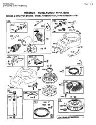
PRIMARY MAINTENANCE39
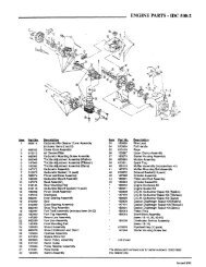
PRIMARY MAINTENANCE40
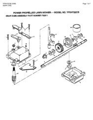
PRIMARY MAINTENANCE41
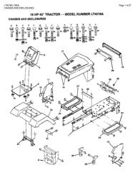
PRIMARY MAINTENANCE42
SERVICE NOTES______________________________________________________________________________________________________________________________________________________________________________________________________________________________________________________________________________________________________________________________________________________________________________________________________________________________________________________________________________________________________________________________________________________________________________________________________________________________________________________________________________________________________________________________________________________________________________________________________________________________________________________________________________________________________________________________________________________________________________________________________________________________________________________________________________________________________________________________________________________________________________________________________________________________________________________________________________________________________________________________________________________________________________________________________________________________________________________________________________________________________________________________________________________________________________________________________________________________________________________________________________________________________________________________________________________________________________________________________________________________________________________________________________________________________________________________________________________________________________________________________________________________________________________________________________________________________________________________________________________________________________________________________________________________________________________________________________________________________________________________________________________________________________________________________________________________________________________________________________________________________________________________________________________________________________________________________________________________________________________________________________________________________________________________________________________________________________________________________________________________________________________________________________________________________________________________43
Safety Instructions & Operator’s Manual forLAWN TRACTORHYDROSTATIC DRIVEELECTRIC CLUTCHSERIES GIMPORTANT<strong>Snapper</strong> products are built using engines that meet or exceed all applicable emissions requirements on the datemanufactured. The labels on those engines contain very important emissions information and critical safetywarnings. Read, Understand, and Follow all warnings and instructions in this manual, the engine manual, and onthe machine, engine and attachments. If you have any questions about your <strong>Snapper</strong> product, contact your localauthorized <strong>Snapper</strong> dealer or contact <strong>Snapper</strong> Customer Service at <strong>Snapper</strong>, McDonough, GA. 30253. Phone: (1-800-935-2967).WARNINGBATTERY POSTS, TERMINALS AND RELATED ACCESSORIES CONTAIN LEAD AND LEAD COMPOUNDS,CHEMICALS KNOWN TO THE STATE OF CALIFORNIA TO CAUSE CANCER AND BIRTH DEFECTS OR OTHERREPRODUCTIVE HARM. WASH HANDS AFTER HANDLING.WARNINGENGINE EXHAUST, SOME OF ITS CONSTITUENTS, AND CERTAIN VEHICLE COMPONENTS CONTAIN OREMIT CHEMICALS KNOWN TO THE STATE OF CALIFORNIA TO CAUSE CANCER OR OTHERREPRODUCTIVE HARM.COPYRIGHT © 2000SNAPPER INC.ALL RIGHTS RESERVEDMANUAL No. 7-4026 (I.R. 9/19/00)44