Data Monitor KS 3002 - Pma-xtra.de
Data Monitor KS 3002 - Pma-xtra.de
Data Monitor KS 3002 - Pma-xtra.de

Create successful ePaper yourself
Turn your PDF publications into a flip-book with our unique Google optimized e-Paper software.
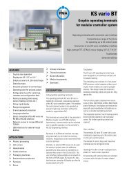
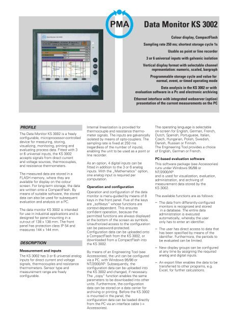
PMA<strong>Data</strong> <strong>Monitor</strong> <strong>KS</strong> <strong>3002</strong>Colour display, CompactFlashSampling rate 250 ms; shortest storage cycle 1sUsable as point or line recor<strong>de</strong>r3 or 6 universal inputs with galvanic isolationVertical display format with selectable channelrepresentation: numeric, scaled, bargraphProgrammable storage cycle and value fornormal, event, or timed operating mo<strong>de</strong><strong>Data</strong> analysis in the <strong>KS</strong> <strong>3002</strong> or withevaluation software in a Pc and electronic archivingEthernet interface with integrated webserver (option)presentation of the current measurements on the PCPROFILEThe <strong>Data</strong> <strong>Monitor</strong> <strong>KS</strong> <strong>3002</strong> is a freelyconfigurable, microprocessor-controlled<strong>de</strong>vice for measuring, storing,visualizing, monitoring, printing an<strong>de</strong>valuating process data. Fitted with 3or 6 universal inputs, the <strong>KS</strong> <strong>3002</strong>accepts signals from direct currentand voltage sources, thermocouples,and resistance thermometers.The measured data are stored in aFLASH memory, where they areavailable for display on the colourscreen. For long-term storage, the dataare written onto a CompactFlash. Bymeans of suitable software, the storeddata can also be used for subsequentevaluation and analysis on a PC.The data monitor <strong>KS</strong> <strong>3002</strong> is inten<strong>de</strong>dfor use in industrial applications and is<strong>de</strong>signed for panel mounting in acut-out of 138 x 138 mm. The frontpanel has protection class IP 54 andmeasures 144 x 144 mm.DESCRIPTIONMeasurement and inputsThe <strong>KS</strong> <strong>3002</strong> has 3 or 6 universal analoginputs for direct current and voltagesignals, thermocouples and resistancethermometers. Sensor type andmeasurement range are freelyconfigurable.Internal linearization is provi<strong>de</strong>d forthermocouple and resistance thermometersignals. The inputs are galvanicallyisolated by means of opto-couplers. Thesampling rate is fixed at 250 ms(regardless of the number of inputs),enabling the unit to be used as a point orline recor<strong>de</strong>r.As an option, 4 digital inputs can befitted in addition to the 3 or 6 analoginputs. With the „Mathematics“ option,one analog input is required percomputation.Operation and configurationOperation and configuration of the datamonitor is menu-gui<strong>de</strong>d by means of 8keys in the front panel. Five of the keysare „softkeys“ whose functions arecontext-<strong>de</strong>pen<strong>de</strong>nt. This ensuresconfi<strong>de</strong>nt operation, because thepermitted functions are always displayedat the bottom of the screen as symbols.Unauthorized access to the configurationcan be password-protected.Configuration data can be uploa<strong>de</strong>d ontoa CompactFlash from the <strong>KS</strong> <strong>3002</strong>, ordownloa<strong>de</strong>d from a CompactFlash intothe <strong>KS</strong> <strong>3002</strong>.By means of an Engineering Tool (seeAccessories), the unit can be configuredvia a PC, with Windows 95/98 orNT/2000/XP. Subsequently, theconfiguration data can be uploa<strong>de</strong>d intothe <strong>KS</strong> <strong>3002</strong> and changed, if necessary.The „copy“ function enables the sameparameters to be downloa<strong>de</strong>d into otherunits. Furthermore, the configurationdata can be stored on a data carrier forarchiving or printing. Before the <strong>KS</strong> <strong>3002</strong>is mounted in the panel, theconfiguration data can be loa<strong>de</strong>d directlyfrom the PC via an interface cable (rAccessories).The operating language is selectableon-screen for English, German, French,Dutch, Spanish, Portuguese, Italian,Czech, Hungarian, Polish, Swedish,Danish, Russian or Finnish.The Engineering Tool provi<strong>de</strong>s a choiceof English, German or French.PC-based evaluation softwareThis software package (see Accessories)runs un<strong>de</strong>r Windows 95/98 orNT/2000/XPand is used for visualization, evaluation,administration, and archiving ofmeasurement data stored by the<strong>KS</strong> <strong>3002</strong>.The available functions are as follows:– The data from differently-configuredmonitors is recognized and storedin a database. The entire dataadministration is executedautomatically, whereby the useronly has to enter an i<strong>de</strong>ntifier.– The user has direct access to data thathas been specified by means of thei<strong>de</strong>ntifier. Furthermore, the periods tobe evaluated can be limited.– New display groups can be configuredat any time by assigning the requiredanalog and digital inputs.– An export filter enables the data to betransferred to other programs, e.g.Excel, for further calculations.
– The evaluation program supportsnetworking, i.e. several users havein<strong>de</strong>pen<strong>de</strong>nt access to the samedata.– By means of an accessory <strong>de</strong>vice, thePCA communication server, the datastored in the FLASH memory of the<strong>KS</strong> <strong>3002</strong> can be read via the serial RS232/RS 485 interface or a mo<strong>de</strong>m.Readout can be triggered manually orwith a timed function.VisualizationFor visualization, the <strong>KS</strong> <strong>3002</strong> is fittedwith a 5-inch (126 mm) STN colourgraphics display with a resolution of320 x 240 pixels. 27 colours ensurebrilliant displays. Measured data aredisplayed vertically, as with conventionalchart recor<strong>de</strong>rs. By means of akey in the front panel, various displayformats are possible for the channels:numeric, scaled, bargraph, or no display. Vertical diagram with numericchannel display, no eventtracks Display width 100 mm Alarm signalling on channel 1Vertical diagram with bargraphchannel display and limitmarks, no event tracksDisplay width 100 mmSoftkeys not displayedFurthermore, it is possible to select alarge numeric display instead of thenormal (vertical) chart display. Anotherfront key enables six event tracks to beactivated for the chart display. Thisreduces the normal 100 mm displaywidth to 72 mm. If „Perforation“ hasbeen selected during parameteradjustment, the chart display showsperforations, which reduces the chartwidth to 94 mm. Vertical movement ofthe chart display <strong>de</strong>pends on theselected storage cycle, and can beadjusted for mm/h, time/grid or storagecycle during parameter adjustment.Vertical diagram with channeldisplay: scaling and limitmarksSix event tracks activatedvia front keyDisplay width 72 mmSoftkeys not displayedVertical diagram withoutchannel display, withperforationDisplay width 94 mmAnother front key selects the display oranalysis of historic data. This enables allthe data stored in the ring buffer to bedisplayed with various zoom settings.The required data for zooming areselected with a cursor line.Various messages in plain text can betriggered by certain events, and arestored in the events’ list. Such eventscan be alarms, digital inputs (option) orsystem messages (e.g. mains supplyon/off). The events’ list is stored in thering buffer and on the CompactFlash.The list can also be displayed at thepush of a front key on the <strong>KS</strong> <strong>3002</strong>. Large numeric display Alarm signalling on channel 2Events’ list; the last 16 entriesare displayed2
<strong>Data</strong> processingAnalog input values are sampledcyclically at fixed intervals of 250 ms, andare stored in a buffer memory. Thestored data is checked for excee<strong>de</strong>dlimits.Depending on the configuration forstorage cycle, storage mo<strong>de</strong> and storagedata (min, max, mean, current ormin+max value), the measurementresults are then passed to a ring buffer(FLASH). There are three operatingmo<strong>de</strong>s, each of which can be configuredfor storage cycle and storage data:• Normal mo<strong>de</strong>:This is the <strong>de</strong>fault setting, and isused as long as there is no alarm,and timed mo<strong>de</strong> has not beenselected.• Event mo<strong>de</strong>:This is triggered by an externalsignal (digital input, group alarm,etc.) and remains active as long asthe trigger signal is present.• Timed mo<strong>de</strong>:This mo<strong>de</strong> is executed once aday during a pre-<strong>de</strong>fined time.The event mo<strong>de</strong> has highest priority,followed by timed mo<strong>de</strong> and normalmo<strong>de</strong>.The internal Flash memory is operatedas a ring buffer, and has a capacity forabout 350.000 measurement values with1MB, with 2MB it has about 850.00.When the memory is full, the ol<strong>de</strong>stdata are overwritten (first in, first out).At regular intervals, the data stored in thememory is copied onto a CompactFlashin 4 kbyte blocks.The CompactFlash is a memory cardwith a capacity of 128MBytes until 2GB(industrial gra<strong>de</strong>). Because every writeprocess is verified, memory faults arerecognized immediately.The unit also monitors the remainingCompactFlash capacity and generates analarm as soon as a configurable„CompactFlash change“ capacity isreached. The alarm signal can be used totrigger a relay (option). With the„CompactFlash update“ function, theCompactFlash manager copies any datafrom the Flash memory that has not yetbeen stored, before a CompactFlash isremoved.Measurement data are stored on theCompactFlash in a special encryptionco<strong>de</strong>. If the CompactFlash is removedfrom the unit, there is no immediate lossof data, because operation of the Flashmemory is not affected. Only when thememory is full, and there is noCompactFlash in the drive, data will beoverwritten.The period required until the storagecapacity of the ring buffer and theCompactFlash is exhausted, <strong>de</strong>pends onthe unit’s configuration, and is variablewithin wi<strong>de</strong> limits: from a few days up toseveral years.• Example:If the <strong>KS</strong> <strong>3002</strong> with 6 channels hasbeen adjusted to 60s in normaloperating mo<strong>de</strong>, the event andtimed mo<strong>de</strong>s have been disabled,and only min, max, mean andcurrent values are to be stored, theresult is a recording period of about10 years for the CompactFlash 128MB, and approx. 30 days with 1MBfor the ring buffer. It is assumedthat no limit signals occur.Behaviour when separating the unit fromthe power supply– Configuration and measurement dataare maintained also after separatingthe <strong>KS</strong> <strong>3002</strong> from the power supply.– When the on-board lithium battery(10 years) or the buffer capacitor(typically 2 weeks) is exhausted, anydata in the Flash memory is lost, andthe internal clock stops. Because theassignment of measured values to thetime will no longer be correct, a newCompactFlash must be inserted andthe internal clock readjusted.If a limit value is excee<strong>de</strong>d, an alarm istriggered. This alarm can be routed to anoutput relay (option), or it can be used toswitch the unit to a different operatingmo<strong>de</strong> (normal, event, or timed). The<strong>de</strong>lay function enables short-term alarms(e.g. during commissioning) to beignored, so that no alarm is triggered.Furthermore, the alarm’s switchinghysteresis is adjustable.InterfaceCurrent process data as well as specialmonitor data can be output via theoptional RS 232 or RS 485 interface.Switchover between RS 232 and RS 485is done via software. With the RS 232interface, up to 15 m of cable areallowed. With RS 485, the cable can beup to 1200 m long.The interface port is a 9-pin D-typefemale connector at the rear of the unit.Transmission protocols for Modbus andJ-bus are available. The transmissionmo<strong>de</strong> is RTU (Remote Terminal Unit).By means of the PCC communicationserver (see Accessories), it is possible toread the data stored in the Flash ringbuffer of the <strong>KS</strong> <strong>3002</strong> via the RS 232/485interface at timed intervals.The switch over between RS232 andRS485-interface is handled in theconfiguration-program.An Ethernet connection with integratedwebserver for the <strong>KS</strong> <strong>3002</strong> can beor<strong>de</strong>red (option)TECHNICAL DATAINPUTAnalog inputsConfigurable for sensor type andmeasuring range.Galvanic isolation between inputs:up to 30 VAC or 50 VDC by means ofopto-couplers.Sampling rate250 ms for 3 or 6 inputs.Resolution: >14 bitsThermocouplesTypeMax. meas. rangeFe-CuNi „L“–200 ... + 900 CFe-CuNi „J“–210 ... +1200 CCu-CuNi „T“–270 ... + 400 CCu-CuNi „U“–200 ... + 600 CNiCr-CuNi „E“ –270 ... +1000 CNiCr-Ni „K“–270 ... +1372 CNiCrSi-NiSi „N“ –270 ... +1300 CSmallest span: 100 KMeasurement error:±0,1% referred to max. measuring range(only guaranteed above -100 °C withType J, above -150 °C with Types U andT, and above -80 °C with Types K, E, andN).3
TypeMax. meas. rangePt10Rh-Pt „S“ –50... + 1768 °CPt13Rh-Pt „R“ –50... + 1768 °CPt30Rh-Pt6Rh „B“ 0... + 1820 CW3Re/W25Re “D” 0... + 2400 °CW5Re/W26Re “C” 0... + 2320 °CSmallest span: 500 KMeasurement error:±0,15% referred to max. measuringrange (only guaranteed above 400 °Cwith Type B, and above 0 °C with TypesS and R). Span start and end of spancan be configured freely in steps of 0,1K within the specified max. measuringranges.Cold junctionInternal: Pt 100Error of internal cold junction: ±1,0 KExternal: with reference thermostatThe cold junction temperature isconfigured for a constant value in therange -50...+100 °C.Resistance thermometers (two, threeor four-wire connection)Type Max. meas. range LinearizationPt 100 –200 … +850 C DIN EN 60751Pt 100 –200 … +650 C JISPt 500 –200 … +850 C DIN EN 60751Pt 1000 –200 … +850 C DIN EN 60751Ni 100 – 60 … +180 CPt50 –200... +1100°CCu50 –50... +200°CSmallest span: 15 KMeasurement error referred to max.measuring range:Sensortype 2&3-wire 4-wirePt100, Pt500, Pt1000,Pt100 JIS,±0,8K ±0,5KPt50, Cu50 ± 0,9 K ± 0,6 KNi100 ± 0,4 K ± 0,4 <strong>KS</strong>pan start and end of span can be configuredfreely in steps of 0,1 K within thespecified max. measuring ranges.Lead resistances– With 3 and 4-wire connection: 30 per lead– With 2-wire connection: 10 perlead– Current through sensor: 0,5 or 0,25mA, <strong>de</strong>pending on sensor typeDirect voltageVoltage signals with the following max.ranges can be measured:Max. meas. range Measurement error–20 ... +70 mV 80 V– 3 ... +105 mV 100 V–10 ... +210 mV 240 V–0,5 ... +12 mV 6mV–0,05 ... +1,2 V 1mV–1,2 ... +1,2 V 2mV–10 ... +12 V 12 mVSmallest span: 5 mVWithin the specified max. measuringranges, span start and end of span canbe configured freely in steps of 0,0 mV.Input impedance:1 M for input signals 100 mV470 k for input signals >100 mVDirect currentCurrent signals with the followingmax. ranges can be measured:Max. meas. range Measurement error– 2 ... +22 mA 20 A–22 ... +22 mA 44 ASmallest span: 0,5 mASpan start and end of span can be configuredfreely in steps of 0,01 mA withinthe specified max. measuring ranges.Voltage drop across input: 210 mV – –Current – –X = monitored; - = not monitoredDigital inputs (option)4 digital inputs to DIN 19 240;max. 1 Hz, max. 32 V,Logic „Low“ (0): -3... +5 V,Logic „High“ (1): 12...30 VSampling rate: min. 1sALARM MONITORINGMin and max limits are monitored foreach channel; freely adjustablehysteresis and alarm <strong>de</strong>lay.COUNTER, MATHEMATICS(OPTION)Since instrument software no.133.03.xx, the <strong>KS</strong> <strong>3002</strong> can be fittedas well as retro-fitted with thefollowing software functions:Counter/ Integrator / Operatingtime counterSix additional channels are available,which can be configured as counter,integrator, or operating time counter.The numeric display has max. 9 digits,and all six channels are shown on aseparate counter page. Countingperiods can be <strong>de</strong>fined as periodic,external, daily, weekly, monthly,yearly, total, or daily from/to. Anexternal, periodic reset or a reset viathe front panel keys .– Counter inputs: binary (digital)inputs, alarms, logic channels,disturbance, Modbus flag.Counter frequency: max. 30 HzEvaluation factor: 0,0001 upto 99999– Integrator inputs: analog inputsIntegrator time base: s, min, h, dEvaluation factor: 0,0001 upto 99999Threshold value: adjustable– Operating time counter input:alarms, logic channels, disturbance,Modbus flag.Time base: s, min, h, dMathematics / LogicSix mathematics channels and sixlogic channels are available. Whilstthe logic channels operate virtually, amathematics channel requires acorresponding analog input channelfor computation. Configuration isonly possible with the EngineeringTool.– Mathematical variables: analoginputs, counter/ integrator channels,binary (digital) inputs, alarms,logic channels, disturbance, Modbusflag.Mathematical operators/functions:+, -, *, /, SQRT, MIN, MAX,SIN, COS, TAN, **, EXP, ABS, INT,FRC, LOG, LN– Logic variables: binary (digital)inputs, alarms, logic channels,disturbance, Modbus flagLogic functions: AND, NOT, OR, XORLogic actions: event track, eventtriggeredoperation, display switchoff,clock synchronization, counter,integrator, or operating time coun- ter,reset for counter/integrator, dis- ablingof front panel keys, relay outputDISPLAY AND OPERATIONSTN colour displayScreen size: 126 mm (5 inches)Resolution: 320 x 240 pixels, 27 coloursOperation and configuration from thefront by means of 8 keys, 5 of whichare softkeys. Alternatively viaEngineering Tool and a PC interfacecable (r Accessories) or bydownloading from a CompactFlash.OUTPUTSRelay (option)3 signalling relay, Change-over contacts:3A, 230 VAC. Combined switchingof safe low voltages (SELV)and mains voltages is not allowed.Voltage source (optional)Output: 24 VDC, 30 mA,short-circuit proof4
POWER SUPPLYSupply voltageAC 110...240 V +10%-15%; 48...63 HzAC/DC 20...53 V; 0/48...63 HzSupply voltage effect
Connecting diagramCut-out for plug-in cable clipsfor strain reliefInput/output connections for 3/6 channelsConnectorAnalog InputsVoltage input 210 mV 1. to 6.Voltage input > 210 mV 1. to 6.Current input 1. to 6.Thermocouples 1. to 6.21.Connecting symbolSupply voltageSupply voltageConnectorPEN (L-)L1 (L+)Relay outputs (optional)Relay K1, K2, K3change-over contactsConnector30., 31., 32.Interface (option)(selection of the active interface is done by configuration in the unit)RS 232 CConnector 2 RxD Received <strong>Data</strong>9pin. SUB-D20.3 TxD Transmitted <strong>Data</strong>5 GND Ground8 CTSRS 4859pin. SUB-DConnector20.Ethernet (Option)(in Connector 21. RJ 45prep)Digital inputs (optional)Supply voltage24V / 30mADigital inputsVoltage controlledLOW = DC -3...5VHIGH = DC 12...30VConnector 33.6 +24V Aux.supply5 GND4 digital input 13 digital input 22 digital input 31 digital input 4Setup interfaceThe Setup interface is located on the frontbehind the lower cover.3 TxD+/RxD+ Received/Transm. data5 GND Ground8 TxD-/RxD- Receive/Transm. dataExample: BE4, controlled byinternal voltage supplyResistance thermometerin two-wire connection1. to 6.Overall dimensions of portable housingResistance thermometerin three-wire connection1. to 6.Resistance thermometerin four-wire connection1. to 6.Overall dimensions2PMAPMAProzess- und Maschinen- Automation GmbHP.O Box 31 02 29D - 34058 KasselTel.: +49 - 561 - 505 1307Fax: +49 - 561 - 505 1710E-mail: mailbox@pma-online.<strong>de</strong>Internet: http://www.pma-online.<strong>de</strong>Your local representativePrinted in Germany - Edition 2010/07 - Subject to alteration without notice - 9498 737 53613