Installation Instructions DFTD-1 Defrost Time Delay
Installation Instructions DFTD-1 Defrost Time Delay
Installation Instructions DFTD-1 Defrost Time Delay

You also want an ePaper? Increase the reach of your titles
YUMPU automatically turns print PDFs into web optimized ePapers that Google loves.
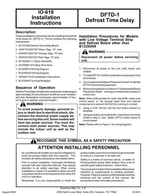
IO-618<strong>Installation</strong><strong>Instructions</strong>DescriptionThese installation instructions are for installing the <strong>Defrost</strong><strong>Time</strong> <strong>Delay</strong> Kit (<strong>DFTD</strong>-1). The kit contains the followingcomponents:1 - B1370786 <strong>Defrost</strong> <strong>Time</strong> <strong>Delay</strong> Board.2 - WAF1015207207 Black 18ga, 15” wire.1 - WAF6015207207 Orange 18ga, 15” wire.1 - WAF2015207207 Red 18ga, 15” wire.4 - B1393802 ½” Nylon Standoffs.2 - B1459807 #72 Blue Wire Nuts.1 - B10259218 Wiring Diagram.1 - B10259220 Wiring Diagram.1 - RF000170 Kit <strong>Installation</strong> <strong>Instructions</strong>.1 - B1378540 Terminal MultiplierSequence of Operation<strong>Defrost</strong> <strong>Time</strong> <strong>Delay</strong> will allow the compressor to deenergizeapproximately 20 seconds prior to defrost cycle initiation,and also deenergize compressor approximately 10 secondsprior to defrost cycle termination.WARNINGTo avoid property damage, personal injuryor death due to electrical shock, disconnectthe electrical power supply beforeservicing this unit. Some models willhave two power sources. You must disconnectboth power sources. This mayinclude the indoor unit as well as theoutdoor unit.<strong>DFTD</strong>-1<strong>Defrost</strong> <strong>Time</strong> <strong>Delay</strong><strong>Installation</strong> Procedures for Modelswith Low Voltage Terminal Stripand <strong>Defrost</strong> Board other thanB1226008WARNINGDisconnect all power before servicingunit.1. Disconnect all power to the unit, both indoor andoutdoor.2. To Install <strong>DFTD</strong>-1 kit the condenser access panel mustbe removed.3. Use “supplemental Board Placement Sheet” to identify<strong>DFTD</strong> control board placement.4. Remove template from bottom of “Suplemental BoardPlacement Sheet”, and tape to referenced location incontrol box.Note: When drilling holes for nylon standoffs, make surecontrol panel is far enough away from any internalcomponents to prevent drill bit from coming in contact.5. Using a 3/16” drill bit, drill the four holes marked ontemplate6. Using provided nylon standoffs, insert them into holesdrilled in step 4, and fasten <strong>DFTD</strong> control board tocontrol panel.Note: Please refer to Figure 1 for wiring diagram.RECOGNIZE THIS SYMBOL AS A SAFETY PRECAUTIONATTENTION INSTALLING PERSONNELAs a professional installer you have an obligation toknow the product better than the customer. Thisincludes all safety precautions and related items.Prior to actual installation, thoroughly familiarizeyourself with this Instruction Manual. Pay specialattention to all safety warnings. Often duringinstallation or repair it is possible to place yourselfin a position which is more hazardous than when theunit is in operation.Remember, it is your responsibility to install theproduct safely and to know it well enough to be ableto instruct a customer in its safe use.Safety is a matter of common sense...a matter ofthinking before acting. Most dealers have a list ofspecific good safety practices...follow them.The precautions listed in this <strong>Installation</strong> Manual areintended as supplemental to existing practices.However, if there is a direct conflict between existingpractices and the content of this manual, theprecautions listed here take precedence.Goodman Mfg. Co., L.P.August 2003 2550 North Loop West, Suite 400, Houston, TX 77092 IO-618
<strong>Installation</strong> <strong>Instructions</strong> for modelswith <strong>Defrost</strong> Control BoardB1226008 without Low VoltageTerminal StripWARNINGDisconnect all power before servicingunit.1. Disconnect all power to the unit, both indoor andoutdoor.2. To Install <strong>DFTD</strong>-1 kit the condenser access panel mustbe removed.3. Use “supplemental Board Placement Sheet” to identify<strong>DFTD</strong> control board placement.4. Remove template from bottom of “Suplemental BoardPlacement Sheet”, and tape to referenced location incontrol box.Note: When drilling holes for nylon standoffs, make surecontrol panel is far enough away from any internalcomponents to prevent drill bit from coming in contact.5. Using a 3/16” drill bit, drill the four holes marked ontemplate6. Using provided nylon standoffs, insert them into holesdrilled in step 4, and fasten <strong>DFTD</strong> control board tocontrol panel.Note: Please refer to Figure 2 for wiring diagram.7. Locate the black wire BK1 in control box harness.Relocate from compressor contactor to <strong>DFTD</strong> controlboard at XFMR-C terminal.IO-6188. Locate terminal multiplier from kit. Place on COMterminal on <strong>DFTD</strong> control board.9. Locate remaining BK1 wire connected between compressorcontactor and C terminal on defrost board.Relocate compressor contactor end to <strong>DFTD</strong> board atCOM terminal so that there is a connection between Cterminal on defrost board.10. Locate black wire (1 of 2) from kit. Connect one end tocommon terminal (where previous BK1 were removed)on compressor contactor and the other end to NCterminal on <strong>DFTD</strong> board.11. Locate black wire (2 of 2) from kit. Connect one end toC terminal on <strong>DFTD</strong> board and the other end to COMterminal on <strong>DFTD</strong> board.12. Locate the orange and red wires from kit. Cut theterminal from one end of each wire. Strip the insulationapproximately 1” from end of wire.13. Locate orange wire on terminal “O” of defrost board. Atopposite end of wire connect orange wire from kit alongwith thermostat wire using blue wire nut provided in kit.Connect opposite end of orange wire provided in kit to“O” terminal on <strong>DFTD</strong> control board.14. Locate red wire on terminal “R” of defrost board. Atopposite end of wire connect red wire provide with kitalong with thermostat wire using blue wire nut providedin kit. Connect opposite end of red wire provided in kitto “XFMR - R” terminal on <strong>DFTD</strong> control board.15. Attach wiring diagram B10259220 on inside of controlbox cover near existing wiring diagram.NOTE: Do not place B10259220 wiring diagram overexisting diagram. Wiring diagram B10259220 is intendedto be used as a supplemental wiring diagram showing<strong>DFTD</strong> control board application.3
IO-618FIGURE 24
SUPPLEMENTAL DEFROST BOARDPLACEMENT SHEETIO-618RHAMODELSRHE & RHFMODELS4.00 in1.5 in5