INSTALLATION MANUAL
INSTALLATION MANUAL
INSTALLATION MANUAL

You also want an ePaper? Increase the reach of your titles
YUMPU automatically turns print PDFs into web optimized ePapers that Google loves.
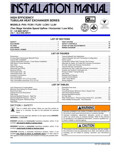
<strong>INSTALLATION</strong> <strong>MANUAL</strong>HIGH EFFICIENCYTUBULAR HEAT EXCHANGER SERIESMODELS: PV8 / FC8V / FL8V / LC8V / LL8V(Two Stage Variable Speed Upflow / Horizontal / Low NOx)57 - 120 MBH INPUT(16.7 - 35.2 KW) INPUTEFFICIENCYRATINGCERTIFIEDISO 9001Certified QualityManagement SystemSAFETY . . . . . . . . . . . . . . . . . . . . . . . . . . . . . . . . . . . . . . . . . . . . . . . . 1DUCTWORK . . . . . . . . . . . . . . . . . . . . . . . . . . . . . . . . . . . . . . . . . . . . 3FILTERS . . . . . . . . . . . . . . . . . . . . . . . . . . . . . . . . . . . . . . . . . . . . . . . 7GAS PIPING . . . . . . . . . . . . . . . . . . . . . . . . . . . . . . . . . . . . . . . . . . . . 7ELECTRICAL POWER . . . . . . . . . . . . . . . . . . . . . . . . . . . . . . . . . . . . 9Dimensions . . . . . . . . . . . . . . . . . . . . . . . . . . . . . . . . . . . . . . . . . . . . . 5Furnace Base Rectangular Blockoff Panel . . . . . . . . . . . . . . . . . . . . . 5Typical Attic Installation . . . . . . . . . . . . . . . . . . . . . . . . . . . . . . . . . . . . 6Typical Suspended Furnace / Crawl Space Installation . . . . . . . . . . . . 6Side Return Cutout Markings . . . . . . . . . . . . . . . . . . . . . . . . . . . . . . . . 7Gas Valve . . . . . . . . . . . . . . . . . . . . . . . . . . . . . . . . . . . . . . . . . . . . . . . 7Upflow Gas Piping . . . . . . . . . . . . . . . . . . . . . . . . . . . . . . . . . . . . . . . . 7Horizontal Gas Piping . . . . . . . . . . . . . . . . . . . . . . . . . . . . . . . . . . . . . 8Electrical Wiring . . . . . . . . . . . . . . . . . . . . . . . . . . . . . . . . . . . . . . . . . 10Thermostat Chart - AC . . . . . . . . . . . . . . . . . . . . . . . . . . . . . . . . . . . . 11Thermostat Chart - HP . . . . . . . . . . . . . . . . . . . . . . . . . . . . . . . . . . . . 12Accessory Connections . . . . . . . . . . . . . . . . . . . . . . . . . . . . . . . . . . . 13Vent Termination . . . . . . . . . . . . . . . . . . . . . . . . . . . . . . . . . . . . . . . . 13Vent Termination 10 ft. (3.0 m) or less . . . . . . . . . . . . . . . . . . . . . . . . 13Vent Termination more than 10 ft. (3.0 m) . . . . . . . . . . . . . . . . . . . . . 13Unit Clearances to Combustibles . . . . . . . . . . . . . . . . . . . . . . . . . . . . . 3Minimum Duct Sizing For Proper Airflow . . . . . . . . . . . . . . . . . . . . . . . 4Round Duct Size . . . . . . . . . . . . . . . . . . . . . . . . . . . . . . . . . . . . . . . . . 4Cabinet and Duct Dimensions . . . . . . . . . . . . . . . . . . . . . . . . . . . . . . . 5Filter Sizes . . . . . . . . . . . . . . . . . . . . . . . . . . . . . . . . . . . . . . . . . . . . . . 7Nominal Manifold Pressure - High Fire . . . . . . . . . . . . . . . . . . . . . . . . 8Nominal Manifold Pressure - Low Fire . . . . . . . . . . . . . . . . . . . . . . . . . 8Ratings & Physical / Electrical Data . . . . . . . . . . . . . . . . . . . . . . . . . . . 9Roof Pitch . . . . . . . . . . . . . . . . . . . . . . . . . . . . . . . . . . . . . . . . . . . . . . 13LIST OF SECTIONSLIST OF FIGURESLIST OF TABLESVENT SYSTEM . . . . . . . . . . . . . . . . . . . . . . . . . . . . . . . . . . . . . . . . .13SAFETY CONTROLS . . . . . . . . . . . . . . . . . . . . . . . . . . . . . . . . . . . .18START-UP AND ADJUSTMENTS . . . . . . . . . . . . . . . . . . . . . . . . . . .18WIRING DIAGRAM . . . . . . . . . . . . . . . . . . . . . . . . . . . . . . . . . . . . . .26Typical Sidewall Vent Application . . . . . . . . . . . . . . . . . . . . . . . . . . . .14Typical Sidewall Vent and Termination Configuration . . . . . . . . . . . .14Home Layout . . . . . . . . . . . . . . . . . . . . . . . . . . . . . . . . . . . . . . . . . . .15Combustion Airflow Path Through The Furnace . . . . . . . . . . . . . . . . .15Alternate Air Intake, Air Outlet and Chimney Connections . . . . . . . . .16Air Inlet, Outlet and Chimney Connections . . . . . . . . . . . . . . . . . . . . .16Typical Chimney Connections . . . . . . . . . . . . . . . . . . . . . . . . . . . . . .16Horizontal Air Inlet, Outlet and Chimney Connections . . . . . . . . . . . .16Outside and Ambient Combustion Air . . . . . . . . . . . . . . . . . . . . . . . . .17Pressure Switch Tubing Routing . . . . . . . . . . . . . . . . . . . . . . . . . . . .18Gas Valve . . . . . . . . . . . . . . . . . . . . . . . . . . . . . . . . . . . . . . . . . . . . . .21Reading Gas Pressure . . . . . . . . . . . . . . . . . . . . . . . . . . . . . . . . . . . .21Furnace Control Board . . . . . . . . . . . . . . . . . . . . . . . . . . . . . . . . . . . .22CFM / Timer Board . . . . . . . . . . . . . . . . . . . . . . . . . . . . . . . . . . . . . . .22Wiring Diagram . . . . . . . . . . . . . . . . . . . . . . . . . . . . . . . . . . . . . . . . . .26Estimated Free Area . . . . . . . . . . . . . . . . . . . . . . . . . . . . . . . . . . . . . .16Free Area . . . . . . . . . . . . . . . . . . . . . . . . . . . . . . . . . . . . . . . . . . . . . .17Unconfined Space Minimum Area in Square Inch . . . . . . . . . . . . . . .17Inlet Gas Pressure Range . . . . . . . . . . . . . . . . . . . . . . . . . . . . . . . . .21Nominal Manifold Pressure . . . . . . . . . . . . . . . . . . . . . . . . . . . . . . . . .21Air Flow Data . . . . . . . . . . . . . . . . . . . . . . . . . . . . . . . . . . . . . . . . . . .23Filter Performance - Pressure Drop Inches W.C. and (kPa) . . . . . . . .24Field Installed Accessories - Non Electrical . . . . . . . . . . . . . . . . . . . .25SECTION I: SAFETYThis is a safety alert symbol. When you see this symbol onlabels or in manuals, be alert to the potential for personalinjury.Understand and pay particular attention to the signal words DANGER,WARNING, or CAUTION.DANGER indicates an imminently hazardous situation, which, if notavoided, will result in death or serious injury.WARNING indicates a potentially hazardous situation, which, if notavoided, could result in death or serious injury.CAUTION indicates a potentially hazardous situation, which, if notavoided may result in minor or moderate injury. It is also used toalert against unsafe practices and hazards involving only property damage.Improper installation may create a condition where the operation ofthe product could cause personal injury or property damage.Improper installation, adjustment, alteration, service or maintenancecan cause injury or property damage. Refer to this manualfor assistance or for additional information, consult a qualified contractor,installer or service agency.This product must be installed in strict compliance with the installationinstructions and any applicable local, state, and national codesincluding, but not limited to building, electrical, and mechanicalcodes.167187-UIM-B-0306
167187-UIM-B-0306SPECIFIC SAFETY RULES AND PRECAUTIONS1. Only Natural gas or Propane (LP) gas are approved for use withthis furnace. Refer to the furnace rating plate or Section IV ofthese instructions.2. Install this furnace only in a location and position as specified inSECTION I of these instructions.3. A gas-fired furnace for installation in a residential garage must beinstalled as specified in SECTION I of these instructions.4. Provide adequate combustion and ventilation air to the furnacespace as specified in SECTION VI of these instructions.5. Combustion products must be discharged outdoors. Connect thisfurnace to an approved vent system only, as specified in SEC-TION VI of these instructions.FIRE OR EXPLOSION HAZARDFailure to follow the safety warnings exactly could result in seriousinjury, death or property damage.Never test for gas leaks with an open flame. Use a commerciallyavailable soap solution made specifically for detection of leaks tocheck all connections. A fire or explosion may result causing propertydamage, personal injury or loss of life.6. Test for gas leaks as specified in SECTION VIII of these instructions.7. Always install the furnace to operate within the furnace’s intendedtemperature rise range. Only connect the furnace to a duct systemwhich has an external static pressure within the allowable range,as specified on the furnace rating plate.8. When a furnace is installed so that supply ducts carry air circulatedby the furnace to areas outside the space containing the furnace,the return air shall also be handled by duct(s) sealed to the furnacecasing and terminating outside the space containing the furnace.9. The furnace is not to be used for temporary heating of buildings orstructures under construction.10. When installed in a Modular Home or building constructed on-site,combustion air shall not be supplied from occupied spaces.11. The size of the unit should be based on an acceptable heat losscalculation for the structure. ACCA, Manual J or other approvedmethods may be used.SAFETY REQUIREMENTS• This furnace should be installed in accordance with all nationaland local building/safety codes and requirements, local plumbingor wastewater codes, and other applicable codes. In the absenceof local codes, install in accordance with the National Fuel GasCode ANSI Z223.1/NFPA 54, National Fuel Gas Code, and/orCAN/CGA B149.1 Natural Gas and Propane Installation Code(latest editions). Furnaces have been certified to the latest editionof standard ANSI Z21-47 • CSA 2.3.• Refer to the unit rating plate for the furnace model number, andthen see the dimensions page of this instruction for return air plenumdimensions in Figure 1. The plenum must be installedaccording to the instructions.• Provide clearances from combustible materials as listed underClearances to Combustibles in Table 1.• Provide clearances for servicing ensuring that service access isallowed for both the burners and blower.• These models ARE NOT CSA listed or approved for installationinto a Manufactured (Mobile) Home.• This furnace is not approved for installation in trailers or recreationalvehicles.• Failure to carefully read and follow all instructions in thismanual can result in furnace malfunction, death, personalinjury and/or property damage.• Furnaces for installation on combustible flooring shall not beinstalled directly on carpeting, tile or other combustible materialother than wood flooring.• Check the rating plate and power supply to be sure that the electricalcharacteristics match. All models use nominal 115 VAC, 1Phase, 60-Hertz power supply. DO NOT CONNECT THIS APPLI-ANCE TO A 50 HZ POWER SUPPLY OR A VOLTAGE ABOVE130 VOLTS.• Furnace shall be installed so the electrical components are protectedfrom water.• Installing and servicing heating equipment can be hazardous dueto the electrical components and the gas fired components. Onlytrained and qualified personnel should install, repair, or servicegas heating equipment. Untrained service personnel can performbasic maintenance functions such as cleaning and replacing theair filters. When working on heating equipment, observe precautionsin the manuals and on the labels attached to the unit andother safety precautions that may apply.• These instructions cover minimum requirements and conform toexisting national standards and safety codes. In some instancesthese instructions exceed certain local codes and ordinances,especially those who have not kept up with changing residentialand modular home construction practices. These instructions arerequired as a minimum for a safe installation.COMBUSTION AIR QUALITY(LIST OF CONTAMINANTS)The furnace will require OUTDOOR AIR for combustion when the furnaceis located in any of the following environments.• Restricted Environments• Commercial buildings• Buildings with indoor pools• Furnaces installed in laundry rooms• Furnaces installed in hobby or craft rooms• Furnaces installed near chemical storage areas• Chemical ExposureThe furnace will require OUTDOOR AIR for combustion when the furnaceis located in an area where the furnace is being exposed to the followingsubstances and / or chemicals.• Permanent wave solutions• Chlorinated waxes and cleaners• Chlorine based swimming pool chemicals• Water softening chemicals• De-icing salts or chemicals• Carbon tetrachloride• Halogen type refrigerants• Cleaning solvents (such as perchloroethylene)• Printing inks, paint removers, varnishes, etc.• Hydrochloric acid• Cements and glues• Anti-static fabric softeners for clothes dryers• Masonry acid washing materialsWhen outdoor air is used for combustion, the combustion air intake ductsystem termination must be located external to the building and in anarea where there will be no exposure to the substances listed above.The furnace area must not be used as a broom closet or for anyother storage purposes, as a fire hazard may be created. Neverstore items such as the following on, near, or in contact with the furnace.1. Spray or aerosol cans, rags, brooms, dust mops, vacuumcleaners or other cleaning tools.2. Soap powders, bleaches, waxes, or other cleaning compounds;plastic items or containers; gasoline, kerosene, cigarettelighter fluid, dry cleaning fluids or other volatile fluid.3. Paint thinners and other painting compounds.4. Paper bags, boxes, or other paper productsNever operate the furnace with the blower door removed. Todo so could result in serious personal injury and/or equipmentdamage.2 Unitary Products Group
167187-UIM-B-0306INSPECTIONAs soon as a unit is received, it should be inspected for possible damageduring transit. If damage is evident, the extent of the damageshould be noted on the carrier’s freight bill. A separate request forinspection by the carrier’s agent should be made in writing. Also, beforeinstallation the unit should be checked for screws or bolts, which mayhave loosened in transit. There are no shipping or spacer bracketswhich need to be removed.FURNACE LOCATION AND CLEARANCESThe furnace shall be located using the following guidelines:1. Where a minimum amount of air intake/vent piping and elbows willbe required.2. As centralized with the air distribution as possible.3. Where adequate combustion air will be available (particularlywhen the appliance is not using outdoor combustion air).4. Where it will not interfere with proper air circulation in the confinedspace.5. Where the outdoor vent terminal will not be blocked or restricted.Refer to “VENT CLEARANCES” located in SECTION VII of theseinstructions. These minimum clearances must be maintained inthe installation.6. Where the unit will be installed in a level position with no morethan 1/4” (6.4 mm) slope side-to-side and front-to-back.Installation in freezing temperatures:1. Furnace shall be installed in an area where ventilation facilitiesprovide for safe limits of ambient temperature under normal operatingconditions. Ambient temperatures may fall below 32° F (0° C)providing the flue temperature does not fall below 260° F (127° C)at any point in the flue pipe between the furnace and the chimneyor a B-Vent. The flue products will condense in the vent pipe if theflue temperature falls below 260° F (127° C) causing the vent pipeto deteriorate rapidly.TABLE 1: Unit Clearances to Combustibles2. Do not allow return air temperature to be below 55º F (13° C) forextended periods. To do so may cause condensation to occur inthe main heat exchanger, leading to premature heat exchangerfailure.Improper installation in an ambient below 32ºF (0.0° C) could createa hazard, resulting in damage, injury or death.3. If this furnace is installed in an unconditioned space and anextended power failure occurs, there will be potential damage tothe internal components. Following a power failure situation, donot operate the unit until inspection and repairs are performed.Clearances for access:Ample clearances should be provided to permit easy access to the unit.The following minimum clearances are recommended:1. Twenty-four (24) inches (61 cm) between the front of the furnaceand an adjacent wall or another appliance, when access isrequired for servicing and cleaning.2. Eighteen (18) inches (46 cm) at the side where access is requiredfor passage to the front when servicing or for inspection orreplacement of flue/vent connections.In all cases, accessibility clearances shall take precedence over clearancesfor combustible materials where accessibility clearances aregreater.Installation in a residential garage:A gas-fired furnace for installation in a residential garage must beinstalled so the burner(s) and the ignition source are located not lessthan 18 inches (46 cm) above the floor, and the furnace must be locatedor protected to avoid physical damage by vehicles.APPLICATIONTOP FRONT REAR LEFT SIDE RIGHT SIDE FLUE FLOOR/In. (cm) In. (cm) In. (cm) In. (cm) In. (cm) In. (cm) BOTTOMCLOSET ALCOVE ATTICLINECONTACTDOWNFLOW 1 (25.4) 6 (15.24) 0 (0.0) 0 (0.0) 3 (7.62) 6 (15.24) 1 (25.4) 1 YES YES YES NODOWNFLOW B-VENT 1 (25.4) 3 (7.62) 0 (0.0) 0 (0.0) 0 (0.0) 1 (25.4) 1 (25.4) 1 YES YES YES NOHORIZONTAL 1 (25.4) 6 (15.24) 0 (0.0) 0 (0.0) 3 (7.62) 6 (15.24) COMBUSTIBLE NO YES YES YES 2HORIZONTAL B-VENT 1 (25.4) 3 (7.62) 0 (0.0) 0 (0.0) 0 (0.0) 1 (25.4) COMBUSTIBLE NO YES YES YES 21. Special floor base or air conditioning coil required for use on combustible floor.2. Line contact only permitted between lines formed by the intersection of the rear panel and side panel (top in horizontal position) of the furnace jacket and building joists, studs or framing.SECTION II: DUCTWORKDUCTWORK GENERAL INFORMATIONThe duct system’s design and installation must:1. Handle an air volume appropriate for the served space and withinthe operating parameters of the furnace specifications.2. Be installed in accordance with standards of NFPA (National FireProtection Association) as outlined in NFPA pamphlets 90A and90B (latest editions) or applicable national, provincial, or state, andlocal fire and safety codes.3. Create a closed duct system. For residential and Modular Homeinstallations, when a furnace is installed so that the supply ductscarry air circulated by the furnace to areas outside the space containingthe furnace, the return air shall also be handled by aduct(s) sealed to the furnace casing and terminating outside thespace containing the furnace.4. Complete a path for heated or cooled air to circulate through theair conditioning and heating equipment and to and from the conditionedspace.When the furnace is used in conjunction with a cooling coil, the coilmust be installed parallel with, or in the supply air side of the furnace toavoid condensation in the primary heat exchanger. When a parallel flowarrangement is used, dampers or other means used to control airflowmust be adequate to prevent chilled air from entering the furnace. Ifmanually operated, the damper must be equipped with means to preventthe furnace or the air conditioner from operating unless the damperis in full heat or cool position.The duct system must be properly sized to obtain the correct airflowfor the furnace size that is being installed.Refer to Table 8 and the furnace rating plate for the correct riserange and static pressuresIf the ducts are undersized, the result will be high duct static pressuresand/or high temperature rises which can result in a heatexchanger OVERHEATING CONDITION. This condition can resultin premature heat exchanger failure, which can result in personalinjury, property damage, or death.The cooling coil must be installed in the supply air duct, downstreamof the furnace. Cooled air may not be passed over the heatexchanger.Unitary Products Group 3
167187-UIM-B-0306B3/4204” Diameter(VENT CONNECTIONS)13-3/4POWER WIRING7/8” HOLE2-1/25-3/814-3/440GAS INLET1-1/4 x 2-1/2T’STAT WIRING7/8” K.O.ACCESSWIRING7/8” K.O.8-3/41632-1/221423-1/21-1/82-1/4AFRONT26-3/430-1/8LEFT SIDE1-3/81-1/45/820 5/8RIGHT SIDECDBBOTTOM IMAGERETURN END4” Diameter24-3/4TOP IMAGESUPPLY ENDFIGURE 1: DimensionsTABLE 4: Cabinet and Duct DimensionsBTUH Input BTUH OutputCFM (m 3 /min) CabinetCabinet DimensionMBH kW MBH kW Size A A (cm) B B (cm) C C (cm) D D (cm)57/42 17.6/12.3 46/34 13.5/10.0 1200 (33.98) A 14 1/2 36.8 13 1/4 33.6 10 1/8 25.7 10 1/8 25.780/59 23.4/17.3 64/48 18.8/14.1 1200 (33.98) A 14 1/2 36.8 13 1/4 33.6 10 1/8 25.7 10 1/8 25.780/59 23.4/17.3 64/48 18.8/14.1 1600 (45.31) B 17 1/2 44.4 16 1/4 41.3 13 1/8 33.3 11 5/8 29.580/59 23.4/17.3 64/48 18.8/14.1 1600 (45.31) C 21 53.3 19 3/4 50.2 16 5/8 42.2 13 3/8 34100/65 29.3/19.1 80/53 23.4/15.5 1600 (45.31) B 17 1/2 44.4 16 1/4 41.3 13 1/8 33.3 11 5/8 29.5100/65 29.3/19.1 80/53 23.4/15.5 1600 (45.31) C 21 53.3 19 3/4 50.2 16 5/8 42.2 13 3/8 34100/65 29.3/19.1 80/53 23.4/15.5 2000 (56.63) C 21 53.3 19 3/4 50.2 16 5/8 42.2 13 3/8 34120/78 35.2/22.9 96/64 28.1/18.8 2000 (56.63) C 21 53.3 19 3/4 50.2 16 5/8 42.2 13 3/8 34RESIDENTIAL AND MODULAR HOME UPFLOWRETURN PLENUM CONNECTIONReturn air may enter the furnace through the side(s) or bottom dependingon the type of application. Return air may not be connected into therear panel of the unit. In order to achieve the airflow indicated, it is recommendedthose applications over 1800 CFM (57 m³/min) use returnair from two sides, one side and the bottom or bottom only. For singlereturn application, see data and notes on blower performance datatables in this manual.BOTTOM RETURN AND ATTIC <strong>INSTALLATION</strong>SBottom return applications normally pull return air through a base platformor return air plenum. Be sure the return platform structure or returnair plenum is suitable to support the weight of the furnace.The furnace base is equipped with a rectangular blockoff panel that canbe removed by performing the following steps:1. Lay the furnace on its back.2. Remove the toe plate. See Figure 2.3. Slide the blockoff panel out and then replace the toe plate.4. Be sure to seal the furnace to plenum connections to prevent airleakage. Refer to Figure 1 for unit and plenum dimensions.Attic installations must meet all minimum clearances to combustiblesand have floor support with required service accessibility.FIGURE 2: Furnace Base Rectangular Blockoff PanelIMPORTANT: If an external mounted filter rack is being used see theinstructions provided with that accessory for proper hole cut size.HORIZONTAL MODELSRemovable RectangularBase Panel.Toe PlateUnitary Products Group 5
167187-UIM-B-0306GASPIPE<strong>MANUAL</strong>SHUT-OFFVALVEGASPIPEDRIPLEGGAS BURNERSGAS VALVEGas piping may be connected from either side of the furnace using anyof the gas pipe entry knockouts on both sides of the furnace. Refer toFigure 1 dimensions.GAS ORIFICE CONVERSION FOR PROPANE (LP)This furnace is constructed at the factory for natural gas-fired operation,but may be converted to operate on propane (LP) gas by using a factory-suppliedLP conversion kit. Follow the instructions supplied withthe LP kit. Refer to Table 6 or the instructions in the propane (LP) conversionkit for the proper gas orifice size.DRIPLEGFIGURE 8: Horizontal Gas Piping<strong>MANUAL</strong>SHUT-OFF VALVEIMPORTANT: An accessible manual shutoff valve must be installedupstream of the furnace gas controls and within 6 feet (1.8 m) of the furnace.The furnace must be isolated from the gas supply piping system byclosing its individual external manual shutoff valve during any pressuretesting of the gas supply piping system at pressures equal to or lessthan 1/2 psig (3.5 kPa).The gas valve body is a very thin casting that cannot take anyexternal pressure. Never apply a pipe wrench to the body of the gasvalve when installing piping. A wrench must be placed on the octagonalhub located on the gas inlet side of the valve. Placing a wrenchto the body of the gas valve will damage the valve causing improperoperation and/or the valve to leak.LoNOx furnaces requiring propane (LP) gas must have the LoNOxscreens removed prior to installation and operation. See theinstructions supplied with the propane conversion kit or the start upprocedure at the back of these instructions on proper removal of theNOx screens.HIGH ALTITUDE GAS ORIFICE CONVERSIONThis furnace is constructed at the factory for natural gas-fired operationat 0 – 8,000 feet (0-m – 2,438 m) above sea level.The manifold pressure must be changed in order to manitain properand safe operation when the furnace is installed in a location where thealtitude is greater than 8,000 feet (2,438 m) above sea level. Refer to toTables 6 & 7 for proper manifold pressure settings.HIGH ALTITUDE PRESSURE SWITCH CONVERSIONFor installation where the altitude is less than 8,000 feet (2,438 m), it isnot required that the pressure switch be changed. For altitudes above8,000 feet (2,438 m), see Table 17 Field Installed Accessories - HighAltitude Pressure SwitchTABLE 6: Nominal Manifold Pressure - High FireGas Heating Value(BTU/cu ft.)Single/Second Stage Manifold Pressures (in wc)Single/Second Stage Manifold Pressures (kpa)Altitude (feet)Altitude (m)0-7999 8000-8999 9000-9999 0-2437 2438-2742 2743-3048800 3.5 3.5 3.529.8 0.87 0.87 0.87850 3.5 3.5 3.5 31.7 0.87 0.87 0.87900 3.5 3.5 3.5 33.5 0.87 0.87 0.87950 3.5 3.5 3.3 35.4 0.87 0.87 0.811000 3.5 3.2 2.9 37.3 0.87 0.80 0.731050 3.5 2.9 2.7 39.1 0.87 0.73 0.671100 3.2 2.7 2.4 41.0 0.80 0.66 0.612500 (LP) 9.8 8.2 7.5 93.2 (LP) 2.44 2.03 1.86Gas Heating Value(MJ/cu m)TABLE 7: Nominal Manifold Pressure - Low FireGas Heating Value(BTU/cu ft.)First Stage Manifold Pressures (in wc)First Stage Manifold Pressures (kpa)Altitude (feet)Altitude (m)0-7999 8000-8999 9000-9999 0-2437 2438-2742 2743-3048800 1.7 1.7 1.729.8 0.42 0.42 0.42850 1.7 1.7 1.7 31.7 0.42 0.42 0.42900 1.7 1.7 1.7 33.5 0.42 0.42 0.42950 1.7 1.7 1.5 35.4 0.42 0.42 0.381000 1.6 1.5 1.4 37.3 0.41 0.37 0.341050 1.5 1.4 1.3 39.1 0.37 0.34 0.311100 1.3 1.2 1.1 41.0 0.34 0.31 0.282500 (LP) 4.1 3.8 3.5 93.2 (LP) 1.03 0.95 0.87Gas Heating Value(MJ/cu m)8 Unitary Products Group
167187-UIM-B-0306PROPANE AND HIGH ALTITUDE CONVERSION KITSIt is very important to choose the correct kit and/or gas orifices for the altitude and the type of gas for which the furnace is being installed.Only use natural gas in furnaces designed for natural gas. Only use propane (LP) gas for furnaces that have been properly converted to use propane(LP) gas. Do not use this furnace with butane gas.Incorrect gas orifices or a furnace that has been improperly converted will create an extremely dangerous condition resulting in premature heatexchanger failure, excessive sooting, high levels of carbon monoxide, personal injury, property damage, a fire hazard and/or death.High altitude and propane (LP) conversions are required in order for the appliance to satisfactory meet the application.An authorized distributor or dealer must make all gas conversions.In Canada, a certified conversion station or other qualified agency, using factory specified and/or approved parts, must perform the conversion.The installer must take every precaution to insure that the furnace has been converted to the proper gas orifice size when the furnace is installed.Do not attempt to drill out any orifices to obtain the proper orifice size. Drilling out a gas orifice will cause misalignment of the burner flames,causing premature heat exchanger burnout, high levels of carbon monoxide, excessive sooting, a fire hazard, personal injury, property damageand/or death.SECTION V: ELECTRICAL POWERElectrical Power ConnectionsField wiring to the unit must be grounded. Electric wires that are fieldinstalled shall conform to the temperature limitation of 63°F (35°C) risewhen installed in accordance with these instructions. Refer to Table 8 inthese instructions for specific furnace electrical data.Use copper conductors only.TABLE 8: Ratings & Physical / Electrical DataInput/CabinetHigh/LowOutput BTU/HHigh/LowNominalAirflowCabinet WidthAFUEBlowerBlower SizeMBH kW MBH kW CFM m 3 mm In cm Hp Amps In cm57/42 16.7/12.3 46/34 13.5/10.0 1200 34.0 14-1/2 36.8 80.0 1/2 7.7 10 x 8 25.4 x 20.380/59 23.4/17.3 64/48 18.8/14.1 1200 34.0 14 1/2 36.8 80.0 1/2 7.7 10 x 8 25.4 x 20.380/59 23.4/17.3 64/48 18.8/14.1 1600 45.3 17-1/2 44.5 80.0 3/4 9.6 10 x 10 25.4 x 25.480/59 23.4/17.3 64/48 18.8/14.1 1600 45.3 21 53.3 80.0 3/4 9.6 10 x 10 25.4 x 25.4100/65 29.3/19.1 80/53 23.4/15.5 1600 45.3 17 1/2 44.5 80.0 3/4 9.6 10 x 10 25.4 x 25.4100/65 29.3/19.1 80/53 23.4/15.5 1600 45.3 21 53.3 80.0 3/4 9.6 10 x 10 25.4 x 25.4100/65 29.3/19.1 80/53 23.4/15.5 2000 56.6 21 53.3 80.0 1 12.8 11 x 10 27.9 x 25.4120/78 35.1/22.9 96/64 28.1/18.8 2000 56.6 21 53.3 80.0 1 12.8 11 x 10 27.9 x 25.4Input/Cabinet Max. Outlet Air Low Fire High FireMax Min. wire Size OperationHigh/LowTemp Air Temp. Rise Air Temp. RiseUnitOver-Current (awg) @ 75 ft WeightAmpsMBH kW °F °C °F °C °F °C Protect one way Lbs Kg57/42 16.7/12.3 160 71.1 25-55 14-31 35-65 19-36 9.0 20 14 107 48.580/52 23.4/17.3 175 79.4 40-70 22-39 40-70 22-39 9.0 20 14 117 43.780/59 23.4/17.3 160 71.1 25-55 14-31 25-55 14-31 12.0 20 14 129 58.580/59 23.4/17.3 160 71.1 25-55 14-31 25-55 14-31 12.0 20 14 140 63.5100/65 29.3/19.1 170 76.7 40-70 22-39 40-70 22-39 12.0 20 14 128 47.8100/65 29.3/19.1 170 76.7 40-70 22-39 40-70 22-39 12.0 20 14 140 63.5100/65 29.3/19.1 170 76.7 40-70 22-39 40-70 22-39 14.0 20 12 145 54.1120/78 35.1/22.9 170 76.7 35-65 19-36 35-65 19-36 14.0 20 12 147 54.91. Annual Fuel Utilization Efficiency (AFUE) numbers are determined in accordance with DOE Test procedures.2. Field wiring and over-current protection (Max Fuse Size) must conform to and be grounded in accordance ANSI/NFPANo. 70-latest edition or the Canadian Electrical Code C222.1 Part 1-latest edition and / or local codes.3. Wire size based on copper conductors, 60º C, 3% voltage drop. "Unit Amps" refers to the full load current.4. Min wire size (awg) @ 75 ft. one way refers to the minimum recommended field installed wire size.Unitary Products Group 9
167187-UIM-B-0306SUPPLY VOLTAGE CONNECTIONSIMPORTANT: The power connection leads and wiring box may be relocatedto the left side of the furnace. Remove the screws and cut wire tieholding excess wiring. Reposition on the left side of the furnace and fastenusing holes provided.1. Provide a power supply separate from all other circuits. Installovercurrent protection and disconnect switch per local/nationalelectrical codes. The switch should be close to the unit for conveniencein servicing. With the disconnect or fused switch in the OFFposition, check all wiring against the unit wiring label. Refer to thewiring diagram, Figure 30, in this instruction.2. Remove the screws retaining the junction box cover. Route thepower wiring through the opening in the unit into the junction boxwith a conduit connector or other proper connection. In the junctionbox there will be three wires, a Black Wire, a White Wire and aGreen Wire. Connect the power supply as shown on the unit wiringlabel on the inside of the blower compartment door or Figure 9.The black furnace lead must be connected to the L1 (hot) wirefrom the power supply. The white furnace lead must be connectedto neutral. Connect the green furnace lead (equipment ground) tothe power supply ground. An alternate wiring method is to use afield provided 2” (5.1 cm) x 4” (10.2 cm) box and cover on the outsideof the furnace. Route the furnace leads into the box using aprotective bushing where the wires pass through the furnacepanel. After making the wiring connections replace the wiring boxcover and screws.3. The furnace's control system requires correct polarity of the powersupply and a proper ground connection. If the power supply polarityis reversed, the control board will flash 9 times. The furnace willnot operate until the polarity is corrected. Refer to "FURNACEDIAGNOSTICS" section of the “User’s Information, Maintenance,& Service Manual” provided with this furnace for symptoms ofreversed power supply polarity.BLK/BLKWHT/WHTGRN/GRNHUMEACWIRING INSIDEJUNCTION BOXBURNERCOMPARTMENTL1(HOT)BLKNWHTGRNGNDJUNCTIONBOXHUM (HOT)EAC (HOT)LOW VOLTAGE CONTROL WIRING CONNECTIONSInstall the field-supplied thermostat by following the instructions thatcome with the thermostat. With the thermostat set in the OFF positionand the main electrical source disconnected, connect the thermostatwiring from the wiring connections on the thermostat to the terminalboard on the ignition module, as shown in Figures 10 & 11. Electronicthermostats may require the common wire to be connected as shown inFigures 10 & 11. Apply strain relief to thermostat wires passing throughcabinet. If air conditioning equipment is installed, use thermostat wiringto connect the Y and C terminals on the furnace control board to theproper wires on the condensing unit (unit outside).Set the heat anticipator in the room thermostat as shown below. Settingit lower will cause short cycles. Setting it higher will cause theroom temperature to exceed the setpoint.Two-Stage ThermostatSingle Stage ThermostatDo not exceed 1.0 amp loading.First StageSecond Stage.4 Amps.6 Amps.4 AmpsIMPORTANT: Some electronic thermostats do not have adjustableheat anticipators. They may have other type cycle rate adjustments.Follow the thermostat manufacturer's instructions.The 24-volt, 40 VA transformer is sized for the furnace componentsonly, and should not be connected to power auxiliary devices such ashumidifiers, air cleaners, etc. The transformer may provide power for anair conditioning unit contactor.For additional connection diagrams for all UPG equipment refer to “LowVoltage System Wiring” document available online at www.upgnet.comin the Product Catalog Section.DOOR SWITCHBLOWERCOMPARTMENTCLASS 2 SYSTEMCONTROL WIRINGTO THERMOSTATIGNITIONMODULEFIGURE 9: Electrical Wiring10 Unitary Products Group
167187-UIM-B-0306AC10 2 Stage Scroll A/C w/ Variable Speed Furnace - PV8/9; (F,L)*8/9V, (G,L)*8/9V, XYG80V-U, XYF80V-U / XYF80V-U*LTHERMOSTAT*DN22U00124C24-Volt CommonYFirst Stage CoolY2Second Stage CoolR24-Volt Hot (Heat XFMR)RC24-Volt Hot (Cool XFMR)E/W1First Stage HeatW2Second Stage HeatGFanTHERMOSTAT*PP32U70124C24-Volt CommonYFirst Stage CoolY2Second Stage CoolR24-Volt Hot (Heat XFMR)RC24-Volt Hot (Cool XFMR)E/W1First Stage HeatW2Second Stage HeatGFanTHERMOSTAT*DN22C00124C24-Volt CommonYFirst Stage CoolY2Second Stage CoolR24-Volt HotWFirst Stage HeatW2Second Stage HeatGFanTHERMOSTAT*DP22U70124C24-Volt CommonY1First Stage CoolY2Second Stage CoolR24-Volt HotE/W1First Stage HeatW2Second Stage HeatGFanTHERMOSTAT*PP32U71124*PP32U72124C24-Volt CommonY1First Stage CoolY2Second Stage CoolR24-Volt HotE/W1First Stage HeatW2Second Stage HeatGFanDHMDehumidistatLMalfunction LightHMHumidistatConnection of the "C"Termainal, 24-VoltCommon, is optionalwhen used with batteriesConnection of the "C"Termainal, 24-VoltCommon, is optionalwhen used with batteriesConnection of the "C"Termainal, 24-Volt Common,is optionalwhen used with batteriesConnection of the "C" Termainal,24-VoltCommon, is optionalwhen used with batteriesStep 1 of Thermostat UserConfiguration Menu must beset to MLTI STGThermostat Installer SetupNumber 1 - System Type -must be set to 6 - 2Heat/2 Cool ConventionalThermostat InstallerSetup Number 0170 -System Type - must beset to 8 - 2 Heat/2 CoolMultistage ConventionalStep 1 of Thermostat UserConfiguration Menumust be set to MS 2Step 16 of ThermostatUser Configuration Menumust be set to ON to useComfort Alert FeaturesThermostat Installer SetupNumber 15 - CompressorProtection - must be set to 5E2/P Switch must be inthe E2 position and theHumidistat Jumper onCFM Control must bein the 'YES' positionfor DehumidificationVARIABLE SPEEDFURNACE CONTROLC24-Volt CommonY1First Stage CoolY/Y2Single/Second Stage CoolR24-Volt HotW/W1Single/First Stage HeatW2Second Stage HeatGFanCFM CONTROLHUMDehumidification - Open on Humidity Rise(O)Reversing Valve– Energized in Cool(X/L)Malfunction Light( ) CONVENIENCE TERMINALNO FUNCTION IN THIS APPLICATION.TWO STAGEAIR CONDITIONINGC24-Volt CommonY1First Stage CoolY2Second Stage CoolR24-Volt HotComfort AlertInterface24V HUMIDIFIER(Optional)FIGURE 10: Thermostat Chart - ACUnitary Products Group 11
167187-UIM-B-0306HP24 Two Stage H/P - H*5B, YZE - w/Variable 2 Stage Furnace, 2 Stage Cooling Ready - PV8/9, (F,L)*8/9V, (G,L)*8/9V, XYG80V-U, XYF80V-U / XYF80V-U*LW/031-01996- Series Demand Control; Hot Heat Pump Mode OR ConventionalTHERMOSTAT THERMOSTAT THERMOSTAT VARIABLE SPEED*PP32U70124 *DN22H00124 *PP32U71124FURNACE CONTROL*DP22U70124 *PP32U72124C24-Volt CommonYFirst Stage Heat/CoolRC24-Volt Hot (Cool XFMR)R24-Volt Hot (Heat XFMR)EEmergency HeatGFanC24-Volt CommonY1First Stage Heat/CoolR24-Volt HotW2Second Stage Auxiliary HeatGFanC24-Volt CommonY1First Stage Heat/CoolR24-Volt HotW2Second Stage Auxiliary HeatGFanC24-Volt CommonY1First Stage CoolY/Y2Single/Second Stage CoolR24-Volt HotW/W1Single/First Stage HeatW2Second Stage HeatGFanO/BReversing ValveLMalfunction LightY2Second Stage Heat/CoolAUXAuxiliary HeatOReversing Valve–Energized in CoolLMalfunction LightY2Second Stage Heat/CoolE/W1First Stage Auxiliary HeatOReversing Valve–Energized in CoolLMalfunction LightY2Second Stage Heat/CoolDHMDehumidistatE/W1First Stage Auxiliary HeatHMHumidistatCFM CONTROL(O)Reversing Valve–Energized in Cool(X/L)Malfunction Light(Y 2)HUMDehumidification - Open on Humidity RiseBonnet Sensor (Optional)24V HUMIDIFIER(Optional)Thermostat Installer Setup Number 0170 -System Type - must be set to12 - 3 Heat/2 Cool Heat PumpSelection of GAS/ELEC switchon thermostat not necessaryStep 1 of Thermostat User ConfigurationMenu must be set to Heat Pump 2Set W2 Delay on furnace to OFFThermostat Installer Setup Number 0190 -Reversing Valve (O/B) Operation - must beset to 0 - O/B Terminal Energized in CoolingStep 1 of Thermostat UserConfiguration Menu must beset to Heat Pump 2E2/P Switch must be in the E2 positionand the Humidistat Jumper on CFMControl must be in the 'YES' position forDehumidification( ) CONVENIENCE TERMINAL. NOFUNCTION IN THIS APPLICATION.Thermostat Installer Setup Number 0200 -Backup Heat Source - must be set to 1 - HeatPump Backup Heat Source is Fossil FuelThermostat Installer Setup Number 0210 -External Fossil Fuel Kit - must be set to 0 -External Fossil Fuel Kit is Controlling HeatPump Backup HeatTWO STAGEHEAT PUMPC24-Volt CommonY1First Stage Heat/CoolY2 OUTSecond Stage Cool OutputR24-Volt HotW1 OUTFirst Stage Auxiliary Heat OutputW2 OUTSecond Stage Auxiliary Heat OutputOReversing Valve–Energized in CoolX/LMalfunction LightY2Second Stage Heat/CoolWAuxiliary HeatBSGBonnet SensorBSBonnet SensorChange FFuel Jumper onHeat Pump to ONFIGURE 11: Thermostat Chart - HP12 Unitary Products Group
167187-UIM-B-0306ACCESSORY CONNECTIONSThe furnace control will allow power-switching control of various accessories.Refer to Figure 12, for connection details.115 VOLTHUMIDIFER115 VOLTELECTRONICAIR CLEANEREAC HOTHUM. HOTBLKWHTBLKWHTFIGURE 12: Accessory ConnectionsEACHUMSWITCHEDCIRCUITSNEUTRALSELECTRONIC AIR CLEANER CONNECTIONTwo 1/4” (0.64 cm) spade terminals (EAC and NEUTRAL) for electronicair cleaner connections are located on the control board. The terminalsprovide 115 VAC (1.0 amp maximum) during circulating blower operation.HUMIDIFIER CONNECTIONTwo 1/4” (0.64 cm) spade terminals (HUM and NEUTRAL) for humidifierconnections are located on the control board. The terminals provide115 VAC (1.0 amp maximum) during heating system operation.TWINNINGThese furnaces are not to be twinned. If more than one furnace isneeded in an application, each furnace must have its own completedduct system and its own wall thermostat.SECTION VI: VENT SYSTEMVENT SAFETYThis Category I, furnace is designed for residential application. It maybe installed without modification in a basement, garage, equipmentroom, alcove, attic or any other indoor location where all required clearanceto combustibles and other restrictions are met.LISTED CAPLISTED GASVENTLOWEST DISCHARGE OPENING12XROOF PITCHIS X/12TABLE 9: Roof PitchROOF PITCH H(min) ft mFlat to 6/12 1.0 0.306/12 to 7/12 1.25 0.38Over 7/12 to 8/12 1.5 0.46Over 8/12 to 9/12 2.0 0.61Over 9/12 to 10/12 2.5 0.76Over 10/12 to 11/12 3.25 0.99Over 11/12 to 12/12 4.0 1.22Over 12/12 to 14/12 5.0 1.52Over 14/12 to 16/12 6.0 1.83Over 16/12 to 18/12 7.0 2.13Over 18/12 to 20/12 7.5 2.27Over 20/12 to 21/12 8.0 2.442 FT (0.6 m)MIN.CHIMNEYRIDGE10 FT (3.0 m) *OR LESSWALL ORPARAPET* 10 FT (3.0 m) OR LESSFROM RIDGE, WALL, OR PARAPET2 FT (0.6 m)MIN. 3 FT (0.9 m)MIN.10 FT (3.0 m)*OR LESS2 FT (0.6 m)MIN.CHIMNEYCHIMNEY3 FT (0.9 m)MIN.FIGURE 14: Vent Termination 10 ft. (3.0 m) or lessMORE THAN*10 FT (3.0 m)3 FT (0.9 m)MIN.FIGURE 13: Vent TerminationH (min) - MINIMUM HEIGHT FROM ROOFTO LOWEST DISCHARGE OPENINGRIDGEWALL ORPARAPETNOTE: NOHEIGHT ABOVEPARAPET REQUIREDWHEN DISTANCEFROM WALLS ORPARAPET IS MORETHAN 10 FT (3.0 m).MORE THAN*10 FT (3.0 m)10 FT(3.0 m)2 FT (0.6 m)MIN.CHIMNEYHEIGHT ABOVE ANYROOF SURFACE WITHIN10 FT (3.0 m) HORIZONTALLY3 FT (0.9 m)MIN.* MORE THAN 10 FT (3.0 m)FROM RIDGE, WALL, OR PARAPETCHIMNEYFIGURE 15: Vent Termination more than 10 ft. (3.0 m)Unitary Products Group 13
167187-UIM-B-0306CATEGORY 1 - 450 F. MAX. VENT TEMP.The venting system must be installed in accordance with Section 5.3,Air for Combustion and Ventilation, of the National Fuel Gas CodeZ223.1/NFPA 54 (latest edition), or Sections 7.2, 7.3 or 7.4 of CSAB149.1, National Gas and Propane Codes (latest edition) or applicableprovisions of the local building code and these instructions.The furnace shall be connected to any type of B, BW or L vent connector,and shall be connected to a factory-built or masonry chimney. Thefurnace shall not be connected to a chimney flue serving a separateappliance designed to burn solid fuel.The furnace rating plate lists the maximum vent gas temperature. Thistemperature must be used to select the appropriate venting materialsand clearances.It is recommended that the appliance is installed in a location where thespace temperature is 32 °F (0°C) or higher. If the appliance is installedin a location where the ambient temperature is below 32 °F (0°C), thecombustion byproducts could condense causing damage to the applianceheat exchanger.IMPORTANT: The “VENT SYSTEM” must be installed as specified inthese instructions for Residential and Modular Homes.This appliance may be common vented with another gas appliance forresidential installations as allowed by the codes and standards listed inthese instructions.Approved Modular Homes must be vented with an approved roof jackand may not be common vented with other appliances.VENTINGCategory I venting consists of vertically venting one or more appliancesin B-vent or masonry chimney (as allowed), using single wall metal pipeor B-vent connectors. Type B-vent system extends in a general verticaldirection and does not contain offsets exceeding 45 degrees. A ventsystem having not more than one 60 degree offset is permitted.The vent system must be attached to the flue collar with a minimum of 2mechanical fasteners such as screws or rivets. See Figure 22.VENTING INTO AN EXISTING CHIMNEYFor Category I installations, the furnace shall be connected to a factorybuilt chimney or vent complying with a recognized standard, or amasonry or concrete chimney lined with a material acceptable to theauthority having jurisdiction. Venting into an unlined masonry chimneyor concrete chimney is prohibited.Whenever possible, B-1 metal pipe should be used for venting. Whereuse of an existing chimney is unavoidable, the following rules must befollowed:1. The masonry chimney must be built and installed in accordancewith nationally recognized building codes or standards and mustbe lined with approved fire clay tile flue liners or other approvedliner material that will resist corrosion, softening, or cracking fromflue gases. THIS FURNACE IS NOT TO BE VENTED INTO ANUNLINED MASONRY CHIMNEY.2. This furnace must be vented into a fire clay tile lined masonrychimney only if a source of dilution air is provided, such as by commonventing with a draft hood equipped water heater. If no sourceof dilution air is available, Type B vent must be used, or masonrychimney vent kit 1CK0603 or 1CK0604 must be used. Refer to theinstructions with the kit to properly apply these masonry chimneykits.3. The chimney must extend at least 3 ft (0.91 m) above the highestpoint where it passes through a roof of a building and at least twofeet higher than any portion of the building with a horizontal distanceof ten feet.4. The chimney must extend at least 5 ft (1.5 m) above the highestequipment draft hood or flue collar.HORIZONTAL SIDEWALL VENTINGFor applications where vertical venting is not possible, the onlyapproved method of horizontal venting is the use of an auxiliary powervent. Approved power venters are Fields Controls Model SWG-4Y orTjernlund Model GPAK-JT. Follow all application and installation detailsprovided by the manufacturer of the power vent. This unit may be horizontallyvented using 4” (10.2 cm) diameter pipe with a minimum lengthof 4.5 feet (1.37 m) and a maximum length of 34.5 feet (10.82 m) withup to 4 elbows.FURNACEFAN ASSISTED FURNACE& WATER HEATERVENTPIPEFIGURE 16: Typical Sidewall Vent ApplicationCELLARWALLOPTIONALSIDEWALLVENT SYSTEM(field supplied)HOTWATERTANKOPTIONALSIDEWALLVENT SYSTEM(field supplied)VENT PIPETOPCOVERBURNERACCESSPANELFAN ASSISTEDFURNACESEXTERIORVENT HOODFURNACEBAROMETRICDAMPERFLUEPIPEFIGURE 17: Typical Sidewall Vent and Termination ConfigurationVENT CLEARANCESIMPORTANT: The vent must be installed with the following minimumclearances as shown in Figure 18, and must comply with local codesand requirements.14 Unitary Products Group
167187-UIM-B-0306VGAVVENT TERMINALDVLEVBFIXEDCLOSEDFCBVVBBVBBIVJXVOPERABLEHMV XKFIXEDCLOSEDXAIR SUPPLYAREA WHERE TERMINAL IS NOT PERMITTEDFIGURE 18: Home LayoutCanadian Installations 1 US Installation 2A. Clearance above grade, veranda, porch, deck, or balcony 12 inches (30 cm) 12 inches (30 cm)B. Clearance to window or door that may be opened12 inches (30 cm) for models 100,000 BTUH (30 kW)C. Clearance to permanently closed window 4 Feet 4 FeetD. Vertical clearance to ventilated soffit locatedabove the terminal within a horizontal distance4 Feet 4 Feetof 2 feet (61 cm) from the center line of the terminalE. Clearance to unventilated soffit 12 Inches 12 InchesF. Clearance to outside corner 12 Inches 12 InchesG. Clearance to inside corner 6 Feet 6 FeetH. Clearance to each side of center line extendedabove meter/regulator assembly3 feet (91 cm) within a height 15 feet (4.5 m) above themeter/regulator assemblyI. Clearance to service regulator vent outlet 3 feet (91 cm) 3 feet (91 cm)J. Clearance to nonmechanical air supply inlet to buildingor the combustion air inlet to any other appliance12 inches (30 cm) for models 100,000 BTUH (30 kW)3 feet (91 cm) within a height 15 feet (4.5 m) above themeter/regulator assembly4 FeetK. Clearance to a mechanical supply inlet 6 feet (1.83 m) 3 feet (91 cm) above if within 10 feet (3 cm) horizontallyL. Clearance above paved sidewalk or paved driveway located on public property 7 feet (2.13 m) † 7 feet (2.13 m) †M.Clearance under veranda, porch, deck, or balcony 12 inches (30.4 cm) 12 inches (30.4 cm)Vent Termination from any Building Surface 12" (30.4 cm) 12" (30.4 cm)Above anticipated snow depth 12" (30.4 cm) 12" (30.4 cm)1. In accordance with the current CSA B149.1-00, Natural Gas and Propane Installation Code.2. In accordance with the current ANSI Z223.1 / NFPA 54, National Gas Code.† A vent shall not terminate directly above a sidewalk or paved driveway that is located between two single family dwellings and serves both dwellings.‡ Permitted only if veranda, porch, deck, or balcony is fully open on a minimum of two sides beneath the floor. For clearance not specified in ANSI Z223.1 / NFPA 54 or CSA B149.1-00.Clearance in accordance with local installation codes and the requirements of the gas supplier and the manufacturer’s Installation Manual.Any fresh air or make up inlet for dryer or furnace area is considered to be forced air inlet.Avoid areas where condensate drippage may cause problems such as above planters, patios, or adjacent to windows where steam may cause fogging.A terminus of a vent shall be either:Fitted with a cap in accordance with the vent manufacturer’s installation instructions, or In accordance with the installation instructions for a special venting system.* Does not apply to multiple installations of this furnace model. Refer to "VENTING MULTIPLE UNITS" in this section of these instructions.IMPORTANT: Consideration must be given for degradation of building materials by flue gases. Sidewall termination may require sealing or shielding of building surfaces with a corrosion resistantmaterial to protect against combustion product corrosion. Consideration must be given to wind direction in order to prevent flue products and/or condensate from being blown againstthe building surfaces. If a metal shield is used it must be a stainless steel material at a minimum dimension of 20 inches. It is recommended that a retaining type collar be used that isattached to the building surface to prevent movement of the vent pipe.Responsibility for the provision of proper adequate venting and air supply for application shall rest with the installer.Vent shall extend high enough above building, or a neighboring obstruction, so that wind from any direction will not create a positive pressure in the vicinity of the vent.HORIZONTAL VENT APPLICATIONS ANDTERMINATIONWhen selecting the location for a horizontal combustion air / vent termination,the following should be considered:1. Observe all clearances listed in vent clearances in these instructions.2. Termination should be positioned where vent vapors will not damageplants or shrubs or air conditioning equipment.3. Termination should be located where it will not be affected by windgusts, light snow, airborne leaves or allow recirculation of fluegases.4. Termination should be located where it will not be damaged orexposed to flying stones, balls, etc.5. Termination should be positioned where vent vapors are not objectionable.6. Horizontal portions of the vent system must slope upwards and besupported to prevent sagging. The vent system may be supportedby the use of clamps or hangers secured to a permanent part ofthe structure every 4 ft. (1.22 m).FAN-ASSISTED COMBUSTION SYSTEMThis appliance is equipped with an integral mechanical means to drawproducts of combustion through the heat exchanger.Ambient Combustion Air SupplyThis type installation will draw the air required for combustion fromwithin the space surrounding the appliance and from areas or roomsadjacent to the space surrounding the appliance. This may be fromwithin the space in a non-confined location or it may be brought into thefurnace area from outdoors through permanent openings or ducts. Asingle, properly sized pipe from the furnace vent connector to the outdoorsmust be provided. For upflow models combustion air is broughtinto the furnace through the unit top panel opening.COMBUSTION AIRATTACH VENT PIPETO FLUE COLLARJUST ABOVE TOPPANEL WITH TWOSCREWSFIGURE 19: Combustion Airflow Path Through The FurnaceUnitary Products Group 15
167187-UIM-B-0306This type of installation requires that the supply air to the appliance(s)be of a sufficient amount to support all of the appliance(s)in the area. Operation of a mechanical exhaust, such as an exhaustfan, kitchen ventilation system, clothes dryer or fireplace may createconditions requiring special attention to avoid unsatisfactoryoperation of gas appliances. A venting problem or a lack of supplyair will result in a hazardous condition, which can cause the applianceto soot and generate dangerous levels of CARBON MONOX-IDE, which can lead to serious injury, property damage and / ordeath.An unconfined space is not less than 50 cu.ft (1.42 m 3 ) per 1,000 Btu/hr (0.2928 kW) input rating for all of the appliances installed in thatarea.Rooms communicating directly with the space containing the appliancesare considered part of the unconfined space, if openings are notfurnished with doors.A confined space is an area with less than 50 cu.ft (1.42 m 3 ) per 1,000Btu/hr (0.2928 kW) input rating for all of the appliances installed in thatarea. The following must be considered to obtain proper air for combustionand ventilation in confined spaces.CHIMNEY ORGAS VENTVENTILATION LOUVERS(each end of attic)Combustion Air Source From OutdoorsThe blocking effects of louvers, grilles and screens must be given considerationin calculating free area. If the free area of a specific louver orgrille is not known, refer to Table 10, to estimate free area.TABLE 10: Estimated Free AreaWood or MetalLouvers or Grilles1/4” (0.635 cm)Screens+mesh or larger 100%+ Do not use less than 1/4” mesh* Free area of louvers and grille varies widely; the installer should follow louver or grillemanufacturer’s instructions.Dampers, Louvers and Grilles (Canada Only)1. The free area of a supply air opening shall be calculated by subtractingthe blockage area of all fixed louvers grilles or screensfrom the gross area of the opening.2. Apertures in a fixed louver, a grille, or screen shall have no dimensionsmaller than 0.25” (6.4 mm).3. A manually operated damper or manually adjustable louvers arenot permitted for use.4. A automatically operated damper or automatically adjustable louversshall be interlocked so that the main burner cannot operateunless either the damper or the louver is in the fully open position.CHIMNEY ORGAS VENTWood 20-25%*Metal 60-70% *OUTLETAIROPENINGALTERNATEAIR INLETFURNACEWATERHEATERINLETAIRFURNACEWATERHEATEROPENINGVENTILATION LOUVERS FOR UNHEATED CRAWL SPACEFIGURE 22: Typical Chimney ConnectionsFIGURE 20: Alternate Air Intake, Air Outlet and Chimney ConnectionsCHIMNEY ORGAS VENTVENTILATION LOUVERS(each end of attic)OUTLETAIR DUCTOUTLETAIRFURNACEWATERHEATERINLETAIR DUCTFURNACEWATERHEATERINLET AIR DUCT[ends 1 ft (30 cm)above floor]FIGURE 23: Horizontal Air Inlet, Outlet and Chimney ConnectionsFIGURE 21: Air Inlet, Outlet and Chimney Connections16 Unitary Products Group
167187-UIM-B-0306TABLE 11: Free AreaCombinedBTUH InputRating ForAll AppliancesMinimum Free Area Required for Each OpeningHorizontal Duct(2,000 BTUH /Sq. In.)Vertical Duct orOpening to Outside(4,000 BTUH /Sq. In.)Round Duct(4,000 BTUH /Sq. In.)60,000 30 in 2 (193 cm 2 ) 15 in 2 (97 cm 2 ) 5” (13 cm)80,000 40 in 2 (258 cm 2 ) 20 in 2 (129 cm 2 ) 5” (13 cm)100,000 50 in 2 (322 cm 2 ) 25 in 2 (161 cm 2 ) 6” (15 cm)120,000 60 in 2 (387 cm 2 ) 30 in 2 (193 cm 2 ) 7” (18 cm)EXAMPLE: Determining Free Area - Vertical Minimum Duct SizeAppliance 1 Appliance 2 Total Input100,000 + 30,000 = 130,000 ÷ 4,000 = 32.5 Sq. In.EXAMPLE: Determining Free Area - Horizontal Minimum Duct SizeAppliance 1 Appliance 2 Total Input100,000 + 30,000 = 130,000 ÷ 2,000 = 65 Sq. In.TABLE 12: Unconfined Space Minimum Area in Square InchBTUH Input RatingMinimum Free Area in Square FeetRequired for Each Opening60,000 375 (34.84 m 2 )80,000 500 (46.45 m 2 )100,000 625 (58.06 m 2 )120,000 750 (69.68 m 2 )EXAMPLE: Square feet is based on 8 foot ceilings.28,000 BTUH X 50 Cubic Ft. = 1,400 = 175 Sq. Ft.1,000 8’ Ceiling HeightWhen a Category I furnace is removed or replaced, the originalventing system may no longer be correctly sized to properly ventthe attached appliances.An improperly sized vent system can cause CARBON MONOXIDEto spill into the living space causing personal injury, and or death.SOFFITVENTGABLEVENTOPTIONALINLET (a)VENTILATEDATTICTOP ABOVEINSULATIONOUTLETAIR (a)GASWATERHEATERVENTILATEDCRAWL SPACEGASVENT5. A square or rectangular shaped duct shall only be usedwhen the required free area of the supply opening is2 29 in (58.06 cm ) or larger. When a square or rectangularduct is used, its small dimensionshall not be less than3 in (7.6 cm).6. An air inlet supply from outdoors shall be equipped witha means to prevent the direct entry of rain and wind.Such means shall not reduce the required free area ofthe air supply opening.7. An air supply inlet opening from the outdoors shallbe located not less than 12” (30.5 cm) above theoutside grade level.FIGURE 24: Outside and Ambient Combustion AirFURNACEAIR SUPPLY OPENINGS AND DUCTS1. An opening may be used in lieu of a duct to provide to provide the outside airsupply to an appliance unless otherwise permitted by the authority havingjurisdiction. The opening shall be located within 12” (30.5 cm) horizontally from,the burner level of the appliance. Refer to “COMBUSTION AIR SOURCE FROMOUTDOORS and VENT AND SUPPLY AIR SAFETY CHECK” in theseinstructions for additional information and safety check procedure.2. The duct shall be either metal, or a material meeting the class 1requirements of CAN4-S110 Standard for Air Ducts.3. The duct shall be least the same cross-sectional area as the freearea of the air supply inlet opening to which it connects.4.The duct shall terminate within 12 in (30.5 cm) above, andwithin 24 in (61 cm) horizontally from, the burner level ofthe appliance having the largest input.SOFFITVENTINLETAIR (b)GABLEVENTVENTILATEDATTICTOP ABOVEINSULATIONGASWATERHEATERGASVENTFURNACEINLETAIR (a)OUTLETAIR (b)INLETAIR (b)GASWATERHEATERGASVENTFURNACEOUTLETAIR (a)INLETAIR (a)COMBUSTION AIR SOURCE FROM OUTDOORS1. Two permanent openings, one within 12 in (30.5 mm) of the top andone within 12 in (30.5 mm) of bottom of the confined space, Twopermanent openings, shall communicate directly or by means of ductswith the outdoors, crawl spaces or attic spaces.2. One permanent openings, commencing within 12 in (30.5 mm)of thetop of the enclosure shall be permitted where the equipment hasclearances of at least 1 in (2.54 cm) from the sides and back and6 in (15.24 cm) from the front of the appliance. The opening shallcommunicate directly with the outdoors and shall have a minimumfree area of:3a. 1 square in per 3000 Btu per hour (6.45 cm per 0.879 kW) of thetotal input rating of all equipment located in the enclosure.b. Not less than the sum of all vent connectors in the confined space.3. The duct shall be least the same cross-sectional area as the freearea of the air supply inlet opening to which it connects.4. The blocking effects of louvers, grilles and screens must be givenconsideration in calculating free area. If the free area of a specificlouver aor grille is not known.Ventilated Combustion AirThe ventilated attic space or a crawl space from which the combustionair is taken must comply with the requirements specified in “AIRSOURCE FROM OUTDOORS” in this instruction or in Section 5.3, Airfor Combustion and Ventilation of the National Fuel Gas Code, ANSIZ223.1 (latest edition). This type installation requires two properly sizedpipes. One brings combustion air from a properly ventilated attic spaceor crawl space and a second pipe that extends from the furnace ventconnection (top right of unit) to the exterior of the building.Vent and Supply (Outside) Air Safety Check ProcedureFor Category I furnaces, vent installations shall be in accordance withParts 7 and 11 of the National Fuel Gas Code, ANSI Z223.1/NFPA 54,and or Section 7 and Appendix B of the CSA B149.1, Natural Gas andPropane Installation Codes, the local building codes, furnace and ventmanufacture's instructions.Multi-story or common venting systems are permitted and must beinstalled in accordance with the National Fuel Gas Code, ANSI Z223.1/NFPA 54 and / or the CSA B149.1, Natural Gas and Propane InstallationCodes, local codes, and the manufacture's instructions.Vent connectors serving Category I furnaces shall not be connectedinto any portion of mechanical draft systems operating under positivepressure.Horizontal portions of the venting system shall be supported to preventsagging using hangers or perforated straps and must slope upwardsnot less than 1/4" per foot (0.635 cm/m) from the furnace to the vent terminal.It is recommended that you follow the venting safety procedure below.This procedure is designed to detect an inadequate ventilation systemthat can cause the appliances in the area to operate improperly causingunsafe levels of Carbon Monoxide or an unsafe condition to occur.Unitary Products Group 17
167187-UIM-B-0306CARBON MONOXIDE POISONING HAZARDFailure to follow the steps outlined below for each appliance connected to the venting system being placed into operation could result in carbonmonxidepoisoning or death.The following steps shall be followed for each appliance connected to the venting system being placed into operation, while all other appliancesconnected to the venting system are not in operation:1. Seal any unused openings in the venting system.2. Inspect the venting system for proper size and horizontal pitch, as required in the National Fuel Gas Code, ANSI Z223.1/NFPA 54 or theCSA B149.1, Natural Gas and Propane Installation Code and these instructions. Determine that there is not blockage or restriction, leakage,corrosion and other deficiencies which could cause an unsafe condition.3. As far as practical, close all building doors and windows and all doors between the space in which the appliance(s) connected to the ventingsystem are located and other spaces of the building.4. Close fireplace dampers.5. Turn on clothes dryers and any appliance not connected to the venting system. Turn on any exhaust fans, such as range hoods and bathroomexhausts, so they are operating at maximum speed. Do not operate a summer exhaust fan.6. Follow the lighting instructions. Place the appliance being inspected into operation. Adjust the thermostat so appliance is operating continuously.7. Test for spillage from draft hood equipped appliances at the draft hood relief opening after 5 minutes of main burner operation. Use theflame of a match or candle.8. If improper venting is observed during any of the above tests, the venting system must be corrected in accordance with the National FuelGas Code, ANSI Z223.1/NFPA 54 and/or CSA B149.1, Natural Gas and Propane Installation Code.9. After it has been determined that each appliance connected to the venting system properly vents when tested as outlined above, returndoors, windows, exhaust fans, fireplace dampers and any other gas-fired burning appliance to their previous conditions of use.SECTION VII: SAFETY CONTROLSCONTROL CIRCUIT FUSEA 3-amp fuse is provided on the control circuit board to protect the 24-volt transformer from overload caused by control circuit wiring errors.This is an ATO 3, automotive type fuse and is located on the controlboard.BLOWER DOOR SAFETY SWITCHThis unit is equipped with an electrical interlock switch mounted in theblower compartment. This switch interrupts all power at the unit whenthe panel covering the blower compartment is removed.Electrical supply to this unit is dependent upon the panel that covers theblower compartment being in place and properly positioned.Main power to the unit must still be interrupted at the main powerdisconnect switch before any service or repair work is to be done tothe unit. Do not rely upon the interlock switch as a main power disconnect.Blower and burner must never be operated without the blowerpanel in place.ROLLOUT SWITCH CONTROLSThese controls are mounted on the burner assembly. If the temperaturearound the burner exceeds the set point, the ignition control and thegas valve are de-energized. The operation of this control indicates amalfunction in the combustion air blower, heat exchanger or a blockedvent pipe connection. Corrective action is required. These are manualreset controls that must be reset before operation can continue.PRESSURE SWITCHESThis furnace is supplied with two pressure switches, which monitor theflow through the combustion air/vent piping system. This switches deenergizethe ignition control module and the gas valve if any of the followingconditions are present. Refer to Figure 25 for tubing connections.1. Blockage of vent piping or terminal.2. Failure of combustion air blower motor.FIGURE 25: Pressure Switch Tubing RoutingLIMIT CONTROLSThere is a high temperature limit control located on the furnace vestibulepanel near the gas valve. This is an automatic reset control thatprovides over temperature protection due to reduced airflow. This maybe caused by:1. A dirty filter.2. If the indoor fan motor should fail.3. Too many supply or retrn registers closed or blocked off.The control module will lockout if the limit trips 5 consecutive times.Control will reset & try ignition again after 1 hour.SECTION VIII: START-UP ANDADJUSTMENTSThe initial start-up of the furnace requires the following additionalprocedures:IMPORTANT: All electrical connections made in the field and in the factoryshould be checked for proper tightness.When the gas supply is initially connected to the furnace, the gas pipingmay be full of air. In order to purge this air, it is recommended that theground union be loosened until the odor of gas is detected. When gas isdetected, immediately retighten the union and check for leaks. Allowfive minutes for any gas to dissipate before continuing with the start-upprocedure. Be sure proper ventilation is available to dilute and carryaway any vented gas.18 Unitary Products Group
167187-UIM-B-0306NOx SCREEN REMOVAL (Lo-NOx Models Only)If the furnace is equipped with NOx screens and is to be used with LP(propane) gas, the screens must be removed prior to startup.1. Make sure that the electrical power to the unit is turned off and thatthe gas supply is turned off at the shutoff valve.2. Remove the blower compartment and burner compartment accessdoors.3. Disconnect the gas supply piping at the union to permit removal ofthe entire burner and gas control assembly from the vestibulepanel. Use the wrench boss on the gas valve when removing orinstalling the piping.4. Unplug the ignitor from the wire harness. Disconnect the flamesensor wires located on top of the air shield. Unplug the gas valvefrom the wiring harness.5. Remove the ignitor and ignitor bracket. Handle the ignitor verycarefully since it is fragile and easily broken.6. Remove the screws holding the burner assembly to the vestibulepanel. It may be necessary to remove the rollout switch bracket(s)to gain access to one or more of these screws.7. Remove the burner assembly. It should be possible to swing theburner assembly out of the way without disconnecting the remainingwires.8. With the burner assembly out of the way, simply slide the NOxscreens out of the heat exchanger tubes and discard the screens.9. Replace all components in reverse order. Reconnect all wiring.TOOLS AND INFORMATION THAT WILL BEREQUIRED IN ORDER TO PROPERLY PERFORM THEFURNACE STARTUP PROCEDURE.1. Call the local gas supplier to obtain heating value of the naturalgas. If you cannot obtain the heating valve of the gas from the gassupplier, you may use a default value of 1030 BTU/SCF (38.8 MJ /m³).2. You will need a thermometer or portable digital thermometer toread the supply and return air temperatures.3. You will need a U-tube manometer or digital equipment that hasthe ability to read pressures between 0 – 15” in.w.c (0 - 3.73 kPa)in order to measure the gas line and the manifold pressures.4. You will need a 3/32” Allen wrench for the pressure port plugs inthe gas valve.5. You will need 2 pieces of 1/8” (0.3 cm) ID flexible tubing that is 12”(30 cm) in length, 2 – pieces of 1/8” (0.3 cm) tubing that are 4”(10.0 cm) in length, a 1/8” (0.3 cm) tee and a 1/8” (0.3 cm) adapterto connect the U-tube manometer or the digital pressure measuringequipment to the gas valve pressure ports.There is an accessory kit (1PK0601) available from Source 1, whichhas the following items:• 1 - 12” (30 cm) length x 1/8” (0.3 cm) diameter tubing• 2 – pieces of 4” (10 cm) length x 1/8” (0.3 cm) diameter tubing• 1 - 5/16” (0.8 cm) tee• 1 – 5/16” (0.8 cm) x 1/8” (3.175 mm) reducing coupling• 1 – 1/8” (0.3 cm) adapterThere is a accessory kit (1PK0602) available from Source 1, which hasthe following items:• 12” (30 cm) length x 1/8” (0.3 cm) diameter tubing• 2 – pieces of 4” (10 cm) length x 1/8” (0.3 cm) diameter tubing• 1 - 5/16” (0.8 cm) tee• 1 – 5/16” (0.8 cm) x 1/8” (0.3 cm) reducing coupling• 1 – 1/8” (0.3 cm) adapter• 1 - Dwyer – ManometerThese items are required in order to properly perform the required startupprocedure.IGNITION SYSTEM SEQUENCE1. Turn the gas supply ON at external valve and main gas valve.2. Set the thermostat above room temperature to call for heat.3. System start-up will occur as follows:a. The induced draft blower motor will start and come up tospeed. Shortly after inducer start-up, the hot surface igniterwill glow for about 17 seconds.b. After this warm up, the ignition module will energize (open)the main gas valve.c. After flame is established, the supply air blower will start inabout 30 seconds.FIRE OR EXPLOSION HAZARDFailure to follow the safety warnings exactly could result in seriousinjury, death or property damage.Never test for gas leaks with an open flame. Use a commerciallyavailable soap solution made specifically for the detection of leaksto check all connections. A fire or explosion may result causingproperty damage, personal injury or loss of life.IMPORTANT: Burner ignition may not be satisfactory on first startupdue to residual air in the gas line or until gas manifold pressure isadjusted. The ignition control will make 3 attempts to light before lockingout.With furnace in operation, check all of the pipe joints, gas valve connectionsand manual valve connections for leakage using an approved gasdetector, a non-corrosive leak detection fluid, or other leak detectionmethods. Take appropriate steps to stop any leak. If a leak persists,replace the component.The furnace and its equipment shutoff valve must be disconnected fromthe gas supply piping system during any pressure testing of that systemat test pressures in excess of 1/2 PSI (3.45 kPa).CALCULATING THE FURNACE INPUT(NATURAL GAS)NOTE: Burner orifices are sized to provide proper input rate using naturalgas with a heating value of 1030 BTU/Ft 3 (38.8 MJ/m 3 ). If theheating value of your gas is significantly different, it may be necessaryto replace the orifices.NOTE: Front door of burner box must be secured when checking gasinput.1. Turn off all other gas appliances connected to the gas meter.2. At the gas meter, measure the time (with a stop watch) it takes touse 2 cubic ft. (0.0566 m 3 .) of gas.3. Calculate the furnace input by using one of the following equations.Unitary Products Group 19
167187-UIM-B-0306In the USA use the following formula to calculate the furnace input.For natural gas multiply the heat content of the gas BTU/SCF or Default 1030 BTU/SCF (38.4 MJ/m 3 ), times 2 cubic ft. (0.056 m) of gas measured atthe gas meter, times a barometric pressure and temperature correction factor of 0.960; times 3600, then divided by the time (In seconds) it took tomeasure 2 cubic ft. (0.056 m) of gas from the gas meter.For propane (LP) gas multiply the heat content of the gas BTU/SCF or Default 2500 BTU/SCF (93.15 MJ/m 3 ), times 1 cubic ft. (0.028 m) of gas measuredat the gas meter, times a barometric pressure and temperature correction factor of 0.960; times 3600, then divided by the time (In seconds) ittook to measure 1 cubic ft. (0.028 m) of gas from the gas meter.The formula for US input calculation using a cubic foot gas meter:BTU/ft 3 x 2 cu.ft. x 0.960 x 3600= BTU/HBTU/ft 3 x 1 cu.ft. x 0.960 x 3600Seconds it took to measure the 2 cu.ft. of gasSeconds it took to measure the 1 cu.ft. of gasNATURAL GAS INPUT CALCULATIONPROPANE (LP) GAS INPUT CALCULATIONEXAMPLE:EXAMPLE:1030 x 2 x 0.960 x 36002500 x 1 x 0.960 x 3600= 78,666.9090.5 108Natural GasPropane Gas1030 BTU/SCF 2500 BTU/SCF= BTU/H= 80,000.00In Canada you will use the following formula to calculate the furnace input if you are using a cubic foot gas meter.For Natural Gas multiply the Heat content of the gas MJ/m 3 (or Default 38.4), times 2 cubic ft. of gas x 0.028 to convert from cubic feet to cubicmeters measured at the gas meter, times a barometric pressure and temperature correction factor of 0.960; times 3600, then divided by the time ittook to measure 2 cubic ft. (0.056 m) of gas from the gas meter.For Propane (LP) Gas multiply the Heat content of the gas MJ/m 3 (or Default 93.15), times 1 cu. ft. of gas x 0.028 to convert from cubic feet to cubicmeters measured at the gas meter, times a barometric pressure and temperature correction factor of 0.960; times 3600, then divided by the time ittook to measure 1 cubic ft. (0.028 m) of gas from the gas meter.The formula for metric input calculation using a cubic foot gas meter:MJ/m 3 x 2 cu.ft. x 0.028 x 0.960 x 3600Seconds it took to measure the 2 cu.ft. of gas= MJ/H x 0.2777 = kW x 3412.14 = BTU/HNATURAL GAS INPUT CALCULATIONEXAMPLE:38.4 x 2 x 0.028 x 0.960 x 360090.5= 82.12 x 0.2777 = 22.80 x 3412.14 = 77,796.80Natural Gas1030 BTU/SCF = 38.4 MJ/m 3PROPANE (LP) GAS INPUT CALCULATIONEXAMPLE:93.15 x 1 x 0.028 x 0.960 x 3600108= 83.46 x 0.2777 = 23.18 x 3412.14 = 79,093.4Propane Gas2500 BTU/SCF = 93.15 MJ/m 3In Canada use the following formula to calculate the furnace input if you are using a gas meter that measures cubic meters.For Natural Gas multiply the Heat content of the gas MJ/m 3 (or Default 38.4), times 0.10 m 3 of gas measured at the gas meter, times a barometricpressure and temperature correction factor of 0.960; times 3600, then divided by the time it took to measure 0.10 m 3 of gas from the gas meter.For Propane (LP) Gas multiply the Heat content of the gas MJ/m 3 (or Default 93.15), times 0.10 m 3 of gas measured at the gas meter, times a barometricpressure and temperature correction factor of 0.960; times 3600, then divided by the time it took to measure 0.10 m 3 of gas from the gasmeter.The formula for metric input calculation using a cubic meter gas meter:MJ/m 3 x m 3 x 0.960 x 3600Seconds it took to measure the 0.10 m 3 of gasNATURAL GAS INPUT CALCULATIONEXAMPLE:38.4 x 0.1 x 0.960 x 3600160Natural Gas1030 BTU/SCF = 38.4 MJ/m 3PROPANE (LP) GAS INPUT CALCULATIONEXAMPLE:93.15 x 0.1 x 0.960 x 3600387Propane Gas2500 BTU/SCF = 93.15 MJ/m 3= MJ/H x 0.2777 = kW x 3412.14 = BTU/H= 82.94 x 0.2777 = 23.03 x 3412.14 = 78,581.60= 83.19 x 0.2777 = 23.10 x 3412.14 = 78,826.3DO NOT ADJUST the manifold pressure regulator if the actual input is equal to or within 8% less than the furnace input specified on the rating plateor if the furnace rise is above the specified rise range on the rating plate.If the actual input is significantly higher than the furnace input specified on the rating plate then replace the gas orifices with the gas orificesof the proper size for the type of gas you are using.20 Unitary Products Group
167187-UIM-B-0306Be sure to relight any gas appliances that were turned off at thestart of this input check.ADJUSTMENT OF MANIFOLD GAS PRESSUREInlet and manifold gas pressure may be measured by connecting the“U” tube manometer to the gas valve with a piece of tubing. Follow theappropriate section in the instructions below. Refer to Figure 26 for adrawing of the locations of the pressure ports on the gas valve.Turn gas off at the ball valve or gas cock on gas supply linebefore the gas valve. Find the pressure ports on the gasvalve marked Out P and In P.1. The manifold pressure must be taken at the port marked OUT P.2. The gas line pressure must be taken at the port marked IN P.3. Using a 3/32” (2.4 mm) Allen wrench, loosen the set screw by turningit 1 turn counter clockwise. DO NOT REMOVE THE SETSCREW FROM THE PRESSURE PORT.Read the inlet gas pressureConnect the positive side of the manometer to the IN P Tap on the gasvalve. Do not connect any tubing to the negative side of the manometer,as it will reference atmospheric pressure. Refer to Figure 27 for connectiondetails.1. Turn gas and electrical supplies on and follow the operatinginstructions to place the unit back in operation.TABLE 13: Inlet Gas Pressure RangeINLET GAS PRESSURE RANGENatural GasPropane (LP)Minimum 4.5” W.C. (1.12 kPa) 8.0” W.C. (1.99 kPa)Maximum 10.5” W.C. (2.61 kPa) 13.0” (3.24 kPa) W.C.IMPORTANT: The inlet gas pressure operating range table specifieswhat the minimum and maximum gas line pressures must be for the furnaceto operate safely. The gas line pressure MUST BE a minimum of• 7” W.C. (1.74 kPA) for Natural Gas• 11” W.C. (2.74 kPA) for Propane (LP) Gasin order to obtain the BTU input specified on the rating plate and/or thenominal manifold pressure specified in these instructions and on therating plate.2. Once the correct gas inlet pressure has been established, seeTable 13, turn the gas valve to OFF and turn the electrical supplyswitch to OFF; then remove the flexible tubing from the gas valvepressure tap and tighten the pressure tap plug using the 3/32” (2.4mm) allen wrench.3. Turn the electrical and gas supplies back on, and with the burnersin operation, check for gas leakage around the gas valve pressureport for leakage using an approved non-corrosive gas leak detectionfluid, or other non-flammable leak detection methods.Read the manifold gas pressureConnect the positive side of the manometer to the adapter previouslyinstalled in the OUT P Tap on the gas valve. Do not connect any tubingto the negative side of the manometer, as it will reference atmosphericpressure. Refer to Figure 27 for connection details.IMPORTANT: The cap for the pressure regulator must be removedentirely to gain access to the adjustment screw. Loosening or tighteningthe cap does not adjust the flow of gas.NOTE: The regulated outlet pressures, both low and high, have beencalibrated at the factory. Additional pressure adjustment shouldnot be necessary. If adjustment is necessary, set to the followingspecifications. After adjustment, check for gas leakage.1. Refer to Figure 26 for location of pressure regulator adjustmentcap and adjustment screws on main gas valve.2. Turn gas and electrical supplies on and follow the operatinginstructions to place the unit back in operation.3. Adjust manifold pressure by adjusting gas valve regulator screwfor the appropriate gas per the following::TABLE 14: Nominal Manifold PressureNOMINAL MANIFOLD PRESSURENatural Gas (High Fire)3.5" w.c. (0.87 kPa)Natural Gas (Low Fire)1.6" w.c. (0.40 kPa)Propane (LP) Gas (High Fire)10.0" w.c. (2.488 kPa)Propane (LP) Gas (Low Fire)4.0" w.c. (0.99 kPa)INLETOUTLETPRESSUREPORTWRENCHBOSSINLETPRESSUREPORTFIGURE 26: Gas ValveIMPORTANT: If gas valve regulator is turned in (clockwise), manifoldpressure is increased. If screw is turned out (counterclockwise), manifoldpressure will decrease.4. After the manifold pressure has been adjusted, re-calculate thefurnace input to make sure you have not exceeded the specifiedinput on the rating plate. Refer to “CALCULATING THE FURNACEINPUT (NATURAL GAS)”.5. Once the correct BTU (kW) input has been established, turn thegas valve to OFF and turn the electrical supply switch to OFF; thenremove the flexible tubing from the gas valve pressure tap andtighten the pressure tap plug using the 3/32” (2.4 mm) Allenwrench.6. Turn the electrical and gas supplies back on, and with the burnersin operation, check for gas leakage around the gas valve pressureport for leakage using an approved non-corrosive gas leak detectionfluid, or other non-flammable leak detection methods.The manifold pressure must be checked with the screw-off cap forthe gas valve pressure regulator in place. If not, the manifold pressuresetting could result in an over-fire condition. A high manifoldpressure will cause an over-fire condition, which could cause prematureheat exchanger failure. If the manifold pressure is too low,sooting and eventual clogging of the heat exchanger could occur.Be sure that gas valve regulator cap is in place and burner box togas valve pressure reference hose is connected.MAINFOLD PRESSURE “U” TUBE CONNECTIONFLAMESENSORBURNERASSEMBLYGASVALVEON OFFSWITCHFIGURE 27: Reading Gas PressureHIGH STAGE REGULATORADJUSTMENTU-TUBEMANOMETERVENTPORTOUTLETLOW STAGE REGULATORADJUSTMENTOUTLETPRESSURETAPMANIFOLDPIPE1/4” TUBING3.5 INWATERCOLUMNGASPRESSURESHOWNUnitary Products Group 21
167187-UIM-B-0306ADJUSTMENT OF TEMPERATURE RISEThe temperature rise, or temperature difference between the returnair and the supply (heated) air from the furnace, must be within therange shown on the furnace rating plate and within the applicationlimitations shown in Table 8 “RATINGS & PHYSICAL/ELECTRICALDATA”.The supply air temperature cannot exceed the “Maximum SupplyAir Temperature” specified in these instructions and on the furnacerating plate. Under NO circumstances can the furnace beallowed to operate above the Maximum Supply Air Temperature.Operating the furnace above the Maximum Supply Air Temperaturewill cause premature heat exchanger failure, high levels of CarbonMonoxide, a fire hazard, personal injury, property damage, and/ordeath.The temperature rise, or temperature difference between the return airand the heated supply air from the furnace, must be within the rangeshown on the furnace rating plate and within the application limitationsas shown in Table 8.After about 20 minutes of operation, determine the furnace temperaturerise. Take readings of both the return air and the heated air in the ducts,about six feet (1.83 m) from the furnace where they will not be affectedby radiant heat. Increase the blower speed to decrease the temperaturerise; decrease the blower speed to increase the rise.VARIABLE SPEED MOTORSThe variable speed motor CFM / Timer Control Board must be configuredso the blower will provide a sufficient airflow so that the furnaceoperates with in the temperature rise range on the rating plate andwithin the application limitations shown in Table 8 in these Instructions.ADJUSTMENT OF FAN CONTROL SETTINGSThis furnace is equipped with a time-on/time-off heating fan control. Thefan on delay is fixed at 30 seconds. The fan off delay has 4 settings (60,90, 120 and 180 seconds). The fan off delay is factory set to 120 seconds.The fan-off setting must be long enough to adequately cool thefurnace, but not so long that cold air is blown into the heated space. Thefan-off timing may be adjusted by positioning the jumper on two of thefour pins as shown in Figure 28.BLOWER OFFDELAY JUMPERW2 DELAYJUMPERCONTINUOUSFAN SPEEDJUMPERTap A is the default profile. It provides a 15-second ramp-up from zeroairflow to full capacity and a 15-second ramp-down from full capacityback to zero airflow. Whenever there is a change in airflow mode, suchas from low heat to high heat, the motor will take 15 seconds to rampfrom one speed to the other.Tap B is the humid profile. This profile is best-suited for installationswhere the humidity is frequently very high during cooling season, suchas in the southern part of the country. On a call for cooling, the blowerwill ramp up to 50% of full capacity and will stay there for two minutes,then will ramp up to 82% of full capacity and will stay there for five minutes,and then will ramp up to full capacity, where it will stay until thewall thermostat is satisfied. In every case, it will take the motor 15 secondsto ramp from one speed to another.Tap C is the dry profile. This profile is best suited to parts of the countrywhere excessive humidity is not generally a problem, where the summermonths are usually dry. On a call for cooling the motor will ramp upto full capacity and will stay there until the thermostat is satisfied. At theend of the cooling cycle, the blower will ramp down to 50% of full capacitywhere it will stay for 60 seconds. Then it will ramp down to zero. Anyramp up to a higher speed will take 30 seconds and any ramp down to alower speed (or off) will take 60 seconds.Tap D is the normal profile, best suited for most of the country, whereneither excessive humidity nor extremely dry conditions are the norm.On a call for cooling, the motor will ramp up to 63% of full capacity andwill stay there for 90 seconds, then will ramp up to full capacity. At theend of the cooling cycle, the motor will ramp down to 63% of full capacityand will stay there for 30 seconds, then will ramp down to zero. Inevery case, it will take the motor 15 seconds to ramp from one speed toanother.CFMTIMERBOARDY1 Y2YW1W W2 R G CFIGURE 28: Furnace Control BoardHeating and Cooling AirflowThe heating and the cooling airflows are preset at the factory. The heatingairflow is set to the maximum CFM. The cooling airflow is set to provide90 percent of the maximum CFM. The heating and cooling airflowsmust be field adjusted to match the HVAC system at installation. SeeTable 15 for the HEAT, COOL and ADJ jumper settings to use for specificairflows.CFM Board - Delay Taps SelectionThe set of jumper pins on the CFM board labeled "DELAY" are used toset the delay profiles for the furnace. These can be chosen so as tomaximize the comfort and sound levels for various regions of the country.FIGURE 29: CFM / Timer BoardContinuous Blower OperationThe blower will run continuously whenever the wall thermostat fanswitch is in the "ON" position. The furnace blower will run at the speedselected on the "FAN SPEED" jumpers on the main control board (HICOOL, LO COOL, HI HEAT or LO HEAT). When the jumper is in the"VS G" position, the blower will run at 50% of the high cool speed.Intermittent Blower CoolingOn cooling/ heating thermostats with a fan switch, when the fan switchis set in the auto position and the thermostat calls for cooling, a circuit iscompleted between the R, Y and G terminals. The motor is energizedthrough the Y1 cool terminal and runs on the speed selected on theCFM Timer board. The fan off setting is fixed at 60 seconds for SEERenhancement.Intermittent Blower HeatingOn cooling/ heating thermostats with a fan switch, when the fan switchis set in the auto position and the thermostat calls for heating, a circuit iscompleted between the R and W terminals. The indoor fan motor isenergized through the W1or W2 heat terminal and runs on the “HighHeat or Low Heat “ speed selected on the CFM Timer board.22 Unitary Products Group
167187-UIM-B-0306TABLE 15: Air Flow DataHIGH / LOW SPEED COOLING AND HEAT PUMP CFMINPUT High Fire: 57,000 / Low Fire: 42,000 INPUT High Fire: 80,000 / Low Fire: 59,000 - 1200 CFMCFM m³/min CFM m³/minJUMPER SETTINGSHigh Low High Low High Low High Low COOL Tap ADJ Tap1342 872 38.0 24.7 1342 872 38.0 24.7 A B1155 751 32.7 21.3 1155 751 32.7 21.3 B B1220 793 34.5 22.5 1220 793 34.5 22.5 A A1050 683 29.7 19.3 1050 683 29.7 19.3 B A1098 714 31.1 20.2 1098 714 31.1 20.2 A C913 593 25.9 16.8 913 593 25.9 16.8 C B945 614 26.8 17.4 945 614 26.8 17.4 B C726 472 20.6 13.4 726 472 20.6 13.4 D B830 540 23.5 15.3 830 540 23.5 15.3 C A660 429 18.7 12.1 660 429 18.7 12.1 D A747 486 21.2 13.7 747 486 21.2 13.7 C C594 386 16.8 10.9 594 386 16.8 10.9 D CINPUT High Fire: 80,000 / Low Fire: 59,000 - 1600 CFM INPUT High Fire: 100,000 / Low Fire: 65,000 - 1600 CFMCFM m³/min CFM m³/minJUMPER SETTINGSHigh Low High Low High Low High Low COOL Tap ADJ Tap*1650 1073 46.7 30.4 1650 1073 46.7 30.4 A B1540 1001 43.6 28.3 1540 1001 43.6 28.3 B B1500 975 42.5 27.6 1500 975 42.5 27.6 A A1400 910 39.6 25.8 1400 910 39.6 25.8 B A1350 878 38.2 24.8 1350 878 38.2 24.8 A C1320 858 37.4 24.3 1320 858 37.4 24.3 C B1260 819 35.7 23.2 1260 819 35.7 23.2 B C1100 715 31.1 20.2 1100 715 31.1 20.2 D B1200 780 34.0 22.1 1200 780 34.0 22.1 C A1000 650 28.3 18.4 1000 650 28.3 18.4 D A1080 702 30.6 19.9 1080 702 30.6 19.9 C C900 585 25.5 16.6 900 585 25.5 16.6 D CINPUT High Fire: 100,000 / Low Fire: 65,000 - 2000 CFM INPUT High Fire: 120,000 / Low Fire: 78,000CFM m³/min CFM m³/minJUMPER SETTINGSHigh Low High Low High Low High Low COOL Tap ADJ Tap*2052 1334 58.1 37.8 2052 1333 58.1 37.7 A B1760 1144 49.8 32.4 1760 1144 49.8 32.4 B B1865 1212 52.8 34.3 1865 1212 52.8 34.3 A A1600 1040 45.3 29.4 1600 1040 45.3 29.4 B A1679 1091 47.5 30.9 1679 1091 47.5 30.9 A C1540 1001 43.6 28.3 1540 1001 43.6 28.3 C B1440 936 40.8 26.5 1440 936 40.8 26.5 B C1320 858 37.4 24.3 1320 858 37.4 24.3 D B1400 910 39.6 25.8 1400 910 39.6 25.8 C A1200 780 34.0 22.1 1200 780 34.0 22.1 D A1260 819 35.7 23.2 1260 819 35.7 23.2 C C1080 702 30.6 19.9 1080 702 30.6 19.9 D CHIGH / LOW HEAT CFMINPUT High Fire: 57,000 / Low Fire: 42,000 INPUT High Fire: 80,000 / Low Fire: 59,000 - 1200 CFMCFM m³/min CFM m³/minJUMPER SETTINGSHigh Low High Low High Low High Low HEAT Tap ADJ Tap*1220 952 34.5 26.9 1315 986 37.2 27.9 A Any950 741 26.9 21.0 1185 889 33.6 25.2 B Any825 644 23.4 18.2 1075 806 30.4 22.8 C Any750 585 21.2 16.6 990 743 28.0 21.0 D AnyINPUT High Fire: 80,000 / Low Fire: 59,000 - 1600 CFM INPUT High Fire: 100,000 / Low Fire: 65,000 - 1600 CFMCFM m³/min CFM m³/minJUMPER SETTINGSHigh Low High Low High Low High Low HEAT Tap ADJ Tap*1700 1411 48.1 40.0 1480 1110 41.9 31.4 A Any1600 1328 45.3 37.6 1350 1013 38.2 28.7 B Any1500 1245 42.5 35.3 1205 904 34.1 25.6 C Any1400 1162 39.6 32.9 1115 836 31.6 23.7 D AnyINPUT High Fire: 100,000 / Low Fire: 65,000 - 2000 CFM INPUT High Fire: 120,000 / Low Fire: 78,000CFM m³/min CFM m³/minJUMPER SETTINGSHigh Low High Low High Low High Low HEAT Tap ADJ Tap*1485 1114 42.1 31.5 2000 1700 56.6 48.1 A Any1375 1031 38.9 29.2 1725 1466 48.8 41.5 B Any1260 945 35.7 26.8 1575 1339 44.6 37.9 C Any1185 889 33.6 25.2 1440 1224 40.8 34.7 D AnyAll CFM’s are shown at 0.5” w.c. external static pressure.These units have variable speed motors that automatically adjust to provide constant CFM from 0.0” to 0.6” w.c. static pressure. From0.6” to 1.0” static pressure, CFM is reduced by 2% per 0.1” increase in static. Operation on duct systems with greater than 1.0” w.c. external static pressure is not recommended.NOTE: At some settings, LOW COOL and/or LOW HEAT airflow may be lower that what is required to operate an airflow switch on certain models of electronic air cleaners. Consult the instructionsfor the electronic air cleaner for further details.NOTE - The ADJ “D” tap should not be used.Unitary Products Group 23
167187-UIM-B-0306FILTER PERFORMANCEThe airflow capacity data published in Table 15 represents blower performanceWITHOUT filters. To determine the approximate blower performanceof the system, apply the filter drop value for the filter beingused or select an appropriate value from the Table 16.NOTE: The filter pressure drop values in Table 16 are typical values forthe type of filter listed and should only be used as a guideline.Actual pressure drop ratings for each filter type vary between filtermanufacturers.TABLE 16: Filter Performance - Pressure Drop Inches W.C. and (kPa)FILTER TYPEMINIMUM OPENING SIZEAIRFLOWDISPOSABLE WASHABLE FIBER PLEATEDRANGE 1 Opening 2 Openings 1 Opening 2 Opening 1 Opening 2 Opening 1 Opening 2 OpeningSq. in. m 2 Sq. in. m 2 In w.c. Pa In w.c. Pa In w.c. Pa In w.c. Pa In w.c. Pa In w.c. Pa0 - 750 230 .15 0.01 2.5 0.01 2.5 0.15 37751 - 1000 330 .21 0.04 10 0.03 7.5 0.20 501001 - 1250 330 .21 0.08 20 0.07 17 0.20 501251 - 1500 330 .21 0.08 20 0.07 17 0.25 621501 - 1750 380 .25 658 .42 0.14 35 0.08 20 0.13 32 0.06 15 0.30 75 0.17 421751 - 2000 380 .25 658 .42 0.17 42 0.09 22 0.15 37 0.07 17 0.30 75 0.17 422001 & Above 463 .30 658 .42 0.17 42 0.09 22 0.15 37 0.07 17 0.30 75 0.17 42APPLYING FILTER PRESSURE DROP TODETERMINE SYSTEM AIRFLOWTo determine the approximate airflow of the unit with a filter in place, followthe steps below:1. Select the filter type.2. Select the number of return air openings or calculate the returnopening size in square inches to determine the proper filter pressuredrop.3. Determine the External System Static Pressure (ESP) without thefilter.4. Select a filter pressure drop from the table based upon the numberof return air openings or return air opening size and add to theESP from Step 3 to determine the total system static.5. If total system static is less than 0.6” w.c. (150 Pa), then the CFMis the value in Table 15.6. If the total system static is greater than 0.6” w.c. (150 Pa), then theCFM is reduced by 2% per 0.1” w.c. (25 Pa) increase in static andcan be calculated by using the following example:Example: For an 80,000 BTUH (23.4 kW) furnace operating on HICOOL TAP B and ADJUST TAP A, it is found that total system static is0.68” w.c. (170 Pa).To determine the system airflow, complete the following steps:Airflow @ 0.60”: 1400 CFM (39.6 m 3 /min)Subtract the total system static from 0.60” w.c. (150 Pa) and divide thisby 0.1” w.c. (25 Pa).0.68 (170 Pa) - 0.60 (150 (Pa) = 0.08 (20 Pa)0.08 (20 Pa) / 0.1 (25 Pa) = 0.8Multiply this by 2% to obtain the percentage reduction in airflow.0.8 x 0.02 = 0.016Multiply percentage reduction in airflow by the airflow in the table toobtain the airflow reduction.0.016 x 1400 (39.6 m 3 /min) = 22 (0.6 m 3 /min)Subtract airflow reduction value from airflow in the table to obtain actualairflow @ 0.68” w.c. (170 Pa) ESP.1400 (39.6 m 3 /min) - 22 (0.6 m 3 /min) = 1378 (39.0 m 3 /min).24 Unitary Products Group
167187-UIM-B-0306TABLE 17: Field Installed Accessories - Non ElectricalMODEL NO. DESCRIPTION USED WITH1NP0580 PROPANE (LP) CONVERSION KIT ALL MODELS1PS0313HIGH ALTITUDE PRESSURE SWITCH KIT57, 80, 100 MBH1PS0314(DOES NOT INCLUDE ORIFICES)120 MBH1SR0302 SIDE RETURN FILTER KIT 1” FILTER ALL MODELS1SR0200 SIDE RETURN FILTER KIT 1-4” FILTER ALL MODELS1BR0114 BOTTOM RETURN FILTER KIT 1” FILTER 14-1/2” CABINETS1BR0214 BOTTOM RETURN FILTER KIT 1-4” FILTER 14-1/2” CABINETS1BR0117 BOTTOM RETURN FILTER KIT 1” FILTER 17-1/2” CABINETS1BR0217 BOTTOM RETURN FILTER KIT 1-4” FILTER 17-1/2” CABINETS1BR0121 BOTTOM RETURN FILTER KIT 1” FILTER 21” CABINETS1BR0221 BOTTOM RETURN FILTER KIT 1-4” FILTER 21” CABINETS1BR0124 BOTTOM RETURN FILTER KIT 1” FILTER 24-1/2” CABINETS1BR0224 BOTTOM RETURN FILTER KIT 1-4” FILTER 24-1/2” CABINETS1HF0801 INTERNAL FILTER KIT WITH 1” FIBER FILTER ALL MODELSUnitary Products Group 25
167187-UIM-B-0306SECTION IX: WIRING DIAGRAMFIGURE 30: Wiring Diagram26 Unitary Products Group
167187-UIM-B-0306NOTESUnitary Products Group 27
NOTESSubject to change without notice. Printed in U.S.A.Copyright © by York International Corp. 2006. All rights reserved.167187-UIM-B-0306Supersedes: 167187-UIM-A-1205Unitary 5005 NormanProduct York OKGroup Drive 73069