INSTALLATION MANUAL
INSTALLATION MANUAL
INSTALLATION MANUAL

Create successful ePaper yourself
Turn your PDF publications into a flip-book with our unique Google optimized e-Paper software.
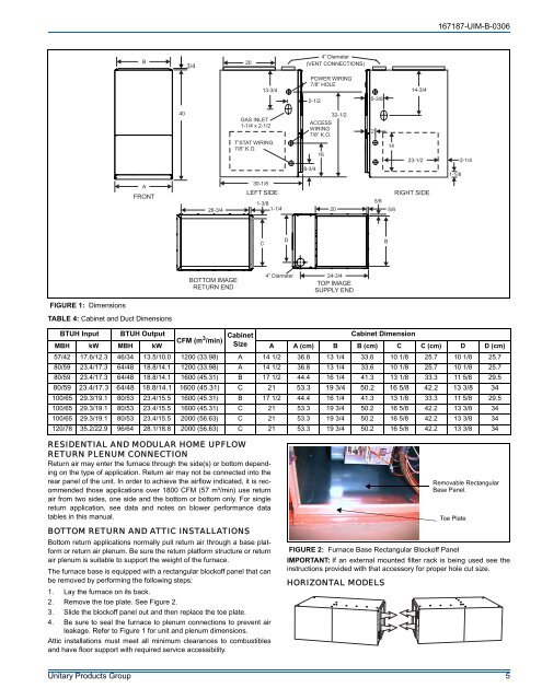
167187-UIM-B-0306B3/4204” Diameter(VENT CONNECTIONS)13-3/4POWER WIRING7/8” HOLE2-1/25-3/814-3/440GAS INLET1-1/4 x 2-1/2T’STAT WIRING7/8” K.O.ACCESSWIRING7/8” K.O.8-3/41632-1/221423-1/21-1/82-1/4AFRONT26-3/430-1/8LEFT SIDE1-3/81-1/45/820 5/8RIGHT SIDECDBBOTTOM IMAGERETURN END4” Diameter24-3/4TOP IMAGESUPPLY ENDFIGURE 1: DimensionsTABLE 4: Cabinet and Duct DimensionsBTUH Input BTUH OutputCFM (m 3 /min) CabinetCabinet DimensionMBH kW MBH kW Size A A (cm) B B (cm) C C (cm) D D (cm)57/42 17.6/12.3 46/34 13.5/10.0 1200 (33.98) A 14 1/2 36.8 13 1/4 33.6 10 1/8 25.7 10 1/8 25.780/59 23.4/17.3 64/48 18.8/14.1 1200 (33.98) A 14 1/2 36.8 13 1/4 33.6 10 1/8 25.7 10 1/8 25.780/59 23.4/17.3 64/48 18.8/14.1 1600 (45.31) B 17 1/2 44.4 16 1/4 41.3 13 1/8 33.3 11 5/8 29.580/59 23.4/17.3 64/48 18.8/14.1 1600 (45.31) C 21 53.3 19 3/4 50.2 16 5/8 42.2 13 3/8 34100/65 29.3/19.1 80/53 23.4/15.5 1600 (45.31) B 17 1/2 44.4 16 1/4 41.3 13 1/8 33.3 11 5/8 29.5100/65 29.3/19.1 80/53 23.4/15.5 1600 (45.31) C 21 53.3 19 3/4 50.2 16 5/8 42.2 13 3/8 34100/65 29.3/19.1 80/53 23.4/15.5 2000 (56.63) C 21 53.3 19 3/4 50.2 16 5/8 42.2 13 3/8 34120/78 35.2/22.9 96/64 28.1/18.8 2000 (56.63) C 21 53.3 19 3/4 50.2 16 5/8 42.2 13 3/8 34RESIDENTIAL AND MODULAR HOME UPFLOWRETURN PLENUM CONNECTIONReturn air may enter the furnace through the side(s) or bottom dependingon the type of application. Return air may not be connected into therear panel of the unit. In order to achieve the airflow indicated, it is recommendedthose applications over 1800 CFM (57 m³/min) use returnair from two sides, one side and the bottom or bottom only. For singlereturn application, see data and notes on blower performance datatables in this manual.BOTTOM RETURN AND ATTIC <strong>INSTALLATION</strong>SBottom return applications normally pull return air through a base platformor return air plenum. Be sure the return platform structure or returnair plenum is suitable to support the weight of the furnace.The furnace base is equipped with a rectangular blockoff panel that canbe removed by performing the following steps:1. Lay the furnace on its back.2. Remove the toe plate. See Figure 2.3. Slide the blockoff panel out and then replace the toe plate.4. Be sure to seal the furnace to plenum connections to prevent airleakage. Refer to Figure 1 for unit and plenum dimensions.Attic installations must meet all minimum clearances to combustiblesand have floor support with required service accessibility.FIGURE 2: Furnace Base Rectangular Blockoff PanelIMPORTANT: If an external mounted filter rack is being used see theinstructions provided with that accessory for proper hole cut size.HORIZONTAL MODELSRemovable RectangularBase Panel.Toe PlateUnitary Products Group 5