INSTALLATION MANUAL
INSTALLATION MANUAL
INSTALLATION MANUAL

Create successful ePaper yourself
Turn your PDF publications into a flip-book with our unique Google optimized e-Paper software.
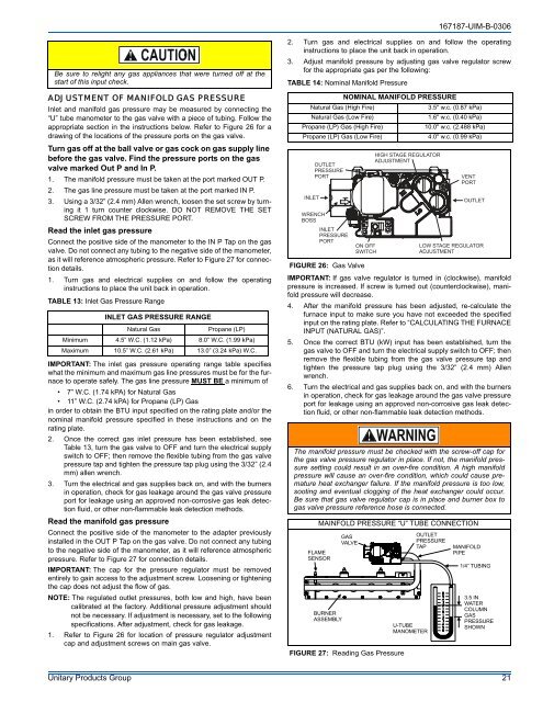
167187-UIM-B-0306Be sure to relight any gas appliances that were turned off at thestart of this input check.ADJUSTMENT OF MANIFOLD GAS PRESSUREInlet and manifold gas pressure may be measured by connecting the“U” tube manometer to the gas valve with a piece of tubing. Follow theappropriate section in the instructions below. Refer to Figure 26 for adrawing of the locations of the pressure ports on the gas valve.Turn gas off at the ball valve or gas cock on gas supply linebefore the gas valve. Find the pressure ports on the gasvalve marked Out P and In P.1. The manifold pressure must be taken at the port marked OUT P.2. The gas line pressure must be taken at the port marked IN P.3. Using a 3/32” (2.4 mm) Allen wrench, loosen the set screw by turningit 1 turn counter clockwise. DO NOT REMOVE THE SETSCREW FROM THE PRESSURE PORT.Read the inlet gas pressureConnect the positive side of the manometer to the IN P Tap on the gasvalve. Do not connect any tubing to the negative side of the manometer,as it will reference atmospheric pressure. Refer to Figure 27 for connectiondetails.1. Turn gas and electrical supplies on and follow the operatinginstructions to place the unit back in operation.TABLE 13: Inlet Gas Pressure RangeINLET GAS PRESSURE RANGENatural GasPropane (LP)Minimum 4.5” W.C. (1.12 kPa) 8.0” W.C. (1.99 kPa)Maximum 10.5” W.C. (2.61 kPa) 13.0” (3.24 kPa) W.C.IMPORTANT: The inlet gas pressure operating range table specifieswhat the minimum and maximum gas line pressures must be for the furnaceto operate safely. The gas line pressure MUST BE a minimum of• 7” W.C. (1.74 kPA) for Natural Gas• 11” W.C. (2.74 kPA) for Propane (LP) Gasin order to obtain the BTU input specified on the rating plate and/or thenominal manifold pressure specified in these instructions and on therating plate.2. Once the correct gas inlet pressure has been established, seeTable 13, turn the gas valve to OFF and turn the electrical supplyswitch to OFF; then remove the flexible tubing from the gas valvepressure tap and tighten the pressure tap plug using the 3/32” (2.4mm) allen wrench.3. Turn the electrical and gas supplies back on, and with the burnersin operation, check for gas leakage around the gas valve pressureport for leakage using an approved non-corrosive gas leak detectionfluid, or other non-flammable leak detection methods.Read the manifold gas pressureConnect the positive side of the manometer to the adapter previouslyinstalled in the OUT P Tap on the gas valve. Do not connect any tubingto the negative side of the manometer, as it will reference atmosphericpressure. Refer to Figure 27 for connection details.IMPORTANT: The cap for the pressure regulator must be removedentirely to gain access to the adjustment screw. Loosening or tighteningthe cap does not adjust the flow of gas.NOTE: The regulated outlet pressures, both low and high, have beencalibrated at the factory. Additional pressure adjustment shouldnot be necessary. If adjustment is necessary, set to the followingspecifications. After adjustment, check for gas leakage.1. Refer to Figure 26 for location of pressure regulator adjustmentcap and adjustment screws on main gas valve.2. Turn gas and electrical supplies on and follow the operatinginstructions to place the unit back in operation.3. Adjust manifold pressure by adjusting gas valve regulator screwfor the appropriate gas per the following::TABLE 14: Nominal Manifold PressureNOMINAL MANIFOLD PRESSURENatural Gas (High Fire)3.5" w.c. (0.87 kPa)Natural Gas (Low Fire)1.6" w.c. (0.40 kPa)Propane (LP) Gas (High Fire)10.0" w.c. (2.488 kPa)Propane (LP) Gas (Low Fire)4.0" w.c. (0.99 kPa)INLETOUTLETPRESSUREPORTWRENCHBOSSINLETPRESSUREPORTFIGURE 26: Gas ValveIMPORTANT: If gas valve regulator is turned in (clockwise), manifoldpressure is increased. If screw is turned out (counterclockwise), manifoldpressure will decrease.4. After the manifold pressure has been adjusted, re-calculate thefurnace input to make sure you have not exceeded the specifiedinput on the rating plate. Refer to “CALCULATING THE FURNACEINPUT (NATURAL GAS)”.5. Once the correct BTU (kW) input has been established, turn thegas valve to OFF and turn the electrical supply switch to OFF; thenremove the flexible tubing from the gas valve pressure tap andtighten the pressure tap plug using the 3/32” (2.4 mm) Allenwrench.6. Turn the electrical and gas supplies back on, and with the burnersin operation, check for gas leakage around the gas valve pressureport for leakage using an approved non-corrosive gas leak detectionfluid, or other non-flammable leak detection methods.The manifold pressure must be checked with the screw-off cap forthe gas valve pressure regulator in place. If not, the manifold pressuresetting could result in an over-fire condition. A high manifoldpressure will cause an over-fire condition, which could cause prematureheat exchanger failure. If the manifold pressure is too low,sooting and eventual clogging of the heat exchanger could occur.Be sure that gas valve regulator cap is in place and burner box togas valve pressure reference hose is connected.MAINFOLD PRESSURE “U” TUBE CONNECTIONFLAMESENSORBURNERASSEMBLYGASVALVEON OFFSWITCHFIGURE 27: Reading Gas PressureHIGH STAGE REGULATORADJUSTMENTU-TUBEMANOMETERVENTPORTOUTLETLOW STAGE REGULATORADJUSTMENTOUTLETPRESSURETAPMANIFOLDPIPE1/4” TUBING3.5 INWATERCOLUMNGASPRESSURESHOWNUnitary Products Group 21