INSTALLATION MANUAL
INSTALLATION MANUAL
INSTALLATION MANUAL

You also want an ePaper? Increase the reach of your titles
YUMPU automatically turns print PDFs into web optimized ePapers that Google loves.
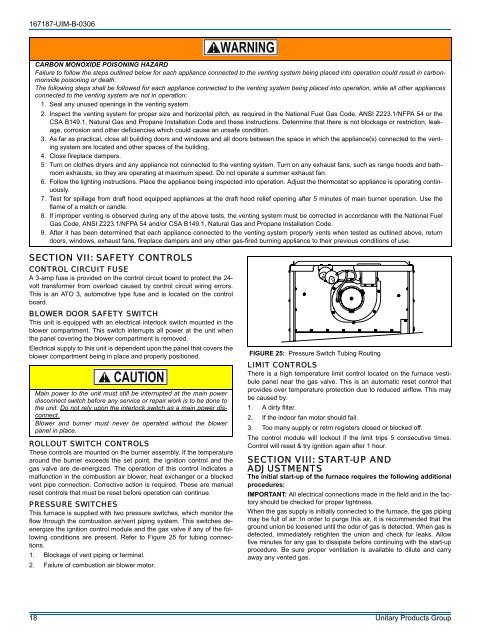
167187-UIM-B-0306CARBON MONOXIDE POISONING HAZARDFailure to follow the steps outlined below for each appliance connected to the venting system being placed into operation could result in carbonmonxidepoisoning or death.The following steps shall be followed for each appliance connected to the venting system being placed into operation, while all other appliancesconnected to the venting system are not in operation:1. Seal any unused openings in the venting system.2. Inspect the venting system for proper size and horizontal pitch, as required in the National Fuel Gas Code, ANSI Z223.1/NFPA 54 or theCSA B149.1, Natural Gas and Propane Installation Code and these instructions. Determine that there is not blockage or restriction, leakage,corrosion and other deficiencies which could cause an unsafe condition.3. As far as practical, close all building doors and windows and all doors between the space in which the appliance(s) connected to the ventingsystem are located and other spaces of the building.4. Close fireplace dampers.5. Turn on clothes dryers and any appliance not connected to the venting system. Turn on any exhaust fans, such as range hoods and bathroomexhausts, so they are operating at maximum speed. Do not operate a summer exhaust fan.6. Follow the lighting instructions. Place the appliance being inspected into operation. Adjust the thermostat so appliance is operating continuously.7. Test for spillage from draft hood equipped appliances at the draft hood relief opening after 5 minutes of main burner operation. Use theflame of a match or candle.8. If improper venting is observed during any of the above tests, the venting system must be corrected in accordance with the National FuelGas Code, ANSI Z223.1/NFPA 54 and/or CSA B149.1, Natural Gas and Propane Installation Code.9. After it has been determined that each appliance connected to the venting system properly vents when tested as outlined above, returndoors, windows, exhaust fans, fireplace dampers and any other gas-fired burning appliance to their previous conditions of use.SECTION VII: SAFETY CONTROLSCONTROL CIRCUIT FUSEA 3-amp fuse is provided on the control circuit board to protect the 24-volt transformer from overload caused by control circuit wiring errors.This is an ATO 3, automotive type fuse and is located on the controlboard.BLOWER DOOR SAFETY SWITCHThis unit is equipped with an electrical interlock switch mounted in theblower compartment. This switch interrupts all power at the unit whenthe panel covering the blower compartment is removed.Electrical supply to this unit is dependent upon the panel that covers theblower compartment being in place and properly positioned.Main power to the unit must still be interrupted at the main powerdisconnect switch before any service or repair work is to be done tothe unit. Do not rely upon the interlock switch as a main power disconnect.Blower and burner must never be operated without the blowerpanel in place.ROLLOUT SWITCH CONTROLSThese controls are mounted on the burner assembly. If the temperaturearound the burner exceeds the set point, the ignition control and thegas valve are de-energized. The operation of this control indicates amalfunction in the combustion air blower, heat exchanger or a blockedvent pipe connection. Corrective action is required. These are manualreset controls that must be reset before operation can continue.PRESSURE SWITCHESThis furnace is supplied with two pressure switches, which monitor theflow through the combustion air/vent piping system. This switches deenergizethe ignition control module and the gas valve if any of the followingconditions are present. Refer to Figure 25 for tubing connections.1. Blockage of vent piping or terminal.2. Failure of combustion air blower motor.FIGURE 25: Pressure Switch Tubing RoutingLIMIT CONTROLSThere is a high temperature limit control located on the furnace vestibulepanel near the gas valve. This is an automatic reset control thatprovides over temperature protection due to reduced airflow. This maybe caused by:1. A dirty filter.2. If the indoor fan motor should fail.3. Too many supply or retrn registers closed or blocked off.The control module will lockout if the limit trips 5 consecutive times.Control will reset & try ignition again after 1 hour.SECTION VIII: START-UP ANDADJUSTMENTSThe initial start-up of the furnace requires the following additionalprocedures:IMPORTANT: All electrical connections made in the field and in the factoryshould be checked for proper tightness.When the gas supply is initially connected to the furnace, the gas pipingmay be full of air. In order to purge this air, it is recommended that theground union be loosened until the odor of gas is detected. When gas isdetected, immediately retighten the union and check for leaks. Allowfive minutes for any gas to dissipate before continuing with the start-upprocedure. Be sure proper ventilation is available to dilute and carryaway any vented gas.18 Unitary Products Group