INSTALLATION & OPERATING INSTRUCTIONS ... - Johnstone Supply
INSTALLATION & OPERATING INSTRUCTIONS ... - Johnstone Supply
INSTALLATION & OPERATING INSTRUCTIONS ... - Johnstone Supply

You also want an ePaper? Increase the reach of your titles
YUMPU automatically turns print PDFs into web optimized ePapers that Google loves.
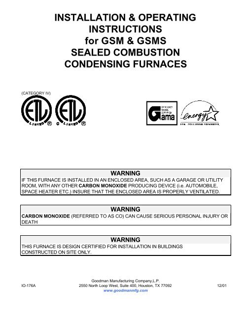
<strong>INSTALLATION</strong> & <strong>OPERATING</strong><strong>INSTRUCTIONS</strong>for GSM & GSMSSEALED COMBUSTIONCONDENSING FURNACES(CATEGORY IV)WARNINGIF THIS FURNACE IS INSTALLED IN AN ENCLOSED AREA, SUCH AS A GARAGE OR UTILITYROOM, WITH ANY OTHER CARBON MONOXIDE PRODUCING DEVICE (i.e. AUTOMOBILE,SPACE HEATER ETC.) INSURE THAT THE ENCLOSED AREA IS PROPERLY VENTILATED.WARNINGCARBON MONOXIDE (REFERRED TO AS CO) CAN CAUSE SERIOUS PERSONAL INJURY ORDEATHWARNINGTHIS FURNACE IS DESIGN CERTIFIED FOR <strong>INSTALLATION</strong> IN BUILDINGSCONSTRUCTED ON SITE ONLY.Goodman Manufacturing Company,L.P.IO-176A 2550 North Loop West, Suite 400, Houston, TX 77092 12/01www.goodmanmfg.com
INDEXWARNINGS & GENERAL INFORMATION 4<strong>INSTALLATION</strong> 5LOCATION 6, 7COMBUSTION AIR 7 - 9VENTING 9,10HORIZONTAL THROUGH THE WALL VENTING 11, 12JOINING PIPE, DRAIN CONNECTIONS 12, 13GAS PIPING AND GAS PIPE CAPACITY TABLE 13, 14CIRCULATING AIR SUPPLY, RETURN AIR 15ELECTRICAL SUPPLY AND CONTROL VOLTAGE CONNECTIONS 16, 17RATING THE FURNACE 17, 18TIMING THE GAS METER, MAIN BURNER ADJUSTMENT 18, 19SAFETY CONTROLS 19 - 21CIRCULATING AIR FILTERS 21TEMP RISE, SERVICE <strong>INSTRUCTIONS</strong> 21, 22SEQUENCE OF OPERATION, REMOVING AN EXISTING APPLIANCE 22 - 24INSPECTING AND CLEANING THE HEAT EXCHANGER 24, 25BLOWER OFF DELAY, EAC CONTROL, HUMIDIFIER CONTROL 25WIRING DIAGRAMS 26, 27LIGHTING <strong>INSTRUCTIONS</strong> 28THIS FURNACE CONTAINS ELECTRONIC COMPONENTS WHICH REQUIRE A DEFINITE GROUND. PROVISIONSARE MADE FOR CONNECTION OF THE GROUND. IF THIS PRODUCT IS NOT PERMANENTLY ANDPOSITIVELYGROUNDED NUMEROUS SERVICE CALLS MAY RESULT. A DEDICATED GROUND FROM THE MAINPOWER SUPPLY OR AN EARTH GROUND MUST BE PROVIDED.IO-1763
HOUSEHOLD CO ALARMS. CURRENT LIMITATIONS TO THEIR EFFECTIVENESS REQUIRESTHAT YOU OTHERWISE CONTINUE TO FOLLOW APPROPRIATE <strong>INSTRUCTIONS</strong> LOCATED INTHE “<strong>INSTALLATION</strong> & <strong>OPERATING</strong> <strong>INSTRUCTIONS</strong>” AND “USERS INFORMATION” MANUALSRELATING TO PROTECTING PERSONS FROM THE RISKS OF CARBON MONOXIDE. REVIEWEACH CO MANUFACTURERS’ EXPLANATION OF THEIR UNIT’S CAPABILITIES AND FOLLOWTHOSE <strong>INSTALLATION</strong> AND <strong>OPERATING</strong> MANUAL WHEN INSTALLING AND <strong>OPERATING</strong>THESE UNITS.WARNINGTHE CIRCULATING AIR DUCTS MUST BE COMPLETELY AND POSITIVELY SEALED TOPREVENT COMBUSTION PRODUCTS, INCLUDING CARBON MONOXIDE, FROM ENTERINGTHE AIR STREAM.WARNINGTO ENSURE PROPER <strong>INSTALLATION</strong> AND OPERATION OF THIS PRODUCT, COMPLETELYREAD AND UNDERSTAND THESE <strong>INSTRUCTIONS</strong> PRIOR TO ATTEMPTING TO ASSEMBLE,INSTALL, MAINTAIN, OR REPAIR. IF THESE <strong>INSTRUCTIONS</strong> ARE NOT FOLLOWED PRECISELYTHERE IS A POTENTIAL OF CARBON MONOXIDE POISONING, WHICH CAN RESULT INSERIOUS ILLNESS OR DEATH.WARNINGTHIS FURNACE WAS EQUIPPED AT THE FACTORY FOR USE WITH NATURAL GAS ONLY. L.P.CONVERSION, IF REQUIRED, MUST BE PERFORMED BY A QUALIFIED TECHNICIAN FAMILIARWITH PERFORMING THIS TYPE OF CONVERSION. IF L.P. CONVERSION IS REQUIRED, ALL<strong>INSTRUCTIONS</strong> INCLUDED WITH THE FACTORY AUTHORIZED KIT MUST BE FOLLOWED. THEONLY KIT THAT MUST BE USED FOR THIS CONVERSION IS THE FACTORY AUTHORIZEDLPM-03 (GSM) OR LPM-04 (GSMS). FAILURE TO FOLLOW THOSE <strong>INSTRUCTIONS</strong> EXPLICITLYMAY CAUSE FIRE, EXPLOSION, OR PERSONAL INJURY AND PROPERTY DAMAGE.WARNINGIF PROHIBITED BY LOCAL CODE, DO NOT INSTALL A LIQUID PETROLEUM GAS BURNINGAPPLIANCE IN A PIT, BASEMENT, OR SIMILAR LOCATION WHERE, L.P., A HEAVIER THAN AIRGAS, CAN COLLECT IN LOW AREAS AND MAY NOT DISPERSE NATURALLY. APPLIANCESSO FUELED SHALL NOT BE INSTALLED IN AN ABOVE GRADE UNDER FLOOR SPACE ORBASEMENT UNLESS SUCH LOCATION IS PROVIDED WITH APPROVED MEANS FORREMOVAL OF UNBURNED GAS.GENERAL INFORMATIONThese Installation and Operating Instructions are intended for use by fully qualified installationtechnicians. Some localities require the installer/servicer to be licensed. If in doubt, check with localauthorities. The GSM furnace is a two stage heating appliance. For optimum use, the GSM furnaceshould use a two stage room thermostat. The GSMS furnace is a single stage furnace and uses asingle stage room thermostat.IO-176 4
<strong>INSTALLATION</strong>: In the USA this furnace MUST be installed in accordance with the latest edition ofthe ANSI Z223.1 booklet entitled “National Fuel Gas Code” (NFPA 54), and the requirements orcodes of the local utility or other authority having jurisdiction. In Canada this furnace must be installedin accordance with the current CAN/ CGA-B149.1 & 2 Gas Installation Codes, local plumbing orwaste water codes and other applicable codes.ANNUAL inspection of the furnace and it’s vent system are strongly recommended. It is the installer’sresponsibility to inform the user of this importance.Additional helpful publications are available from the NFPA are, NFPA 90A - Installation of AirConditioning and Ventilating System and NFPA90B - Warm Air Heating and Air ConditioningSystem. These publications are available from:National Fire Protection Association, Inc.Batterymarch ParkQuincy, MA 02269These furnaces meet the California NOX emission standards and the California efficiency standards.The GSM & GSMS furnace may be installed as either a Direct Vent or Non-Direct Vent Furnace.These furnaces are designed to be an UPFLOW or HORIZONTAL furnace. The following sketchshows a typical installation:TYPICAL UPFLOW<strong>INSTALLATION</strong>DRAINHOSEIO-176 5
LOCATIONDO NOT install this furnace in a mobile home. This furnace is designed only for installation inbuildings constructed on site and connected to ductwork. When installed in a utility room or closet, thedoor should be wide enough to allow the largest part of the furnace to enter, or to permit thereplacement of another appliance, such as a water heater. This furnace is designed to be installedindoors only. DO NOT install outdoors. This furnace should be installed in such a manner so that it isprotected from water. If any components should become submerged under water, replace those partsbefore returning the furnace to operation. DO NOT use as a construction heater. DO NOT install in anarea where freezing can occur without properly protecting the unit and drain system. DO NOT installin a room designed to be used as a bedroom, bathroom, storage closet, or in any enclosed spacewith access only through such room or space. The furnace and it’s individual shut-off must bedisconnected from the gas supply piping system during any pressure testing of that system at testpressures in excess of 1/2 psig (3.5kPa) The furnace must be isolated from the gas supply pipingsystem by closing it’s individual manual shut-off valve during any pressure testing of the gas supplypiping system at pressures equal to or less than 1/2 psig (3.5 kPa).MINIMUM CLEARANCES TO COMBUSTIBLE SURFACESUnobstructed front clearance of 24” for servicing is recommended.VENT - 0” FRONT - 3” RIGHT SIDE - 1”LEFT SIDE - 1” REAR - 0” TOP OF PLENUM - 1”ACCESSIBILITY CLEARANCE, WHERE GREATER, SHOULD TAKE PRECEDENCE OVERMINIMUM FIRE PROTECTION CLEARANCE.A gas fired furnace for installation in a residential garage must be installed so that the ignition sourceand burners are located not less than eighteen inches (18”) above the floor and is protected orlocated to prevent physical damage by vehicles. A gas furnace must not be installed directly oncarpeting, tile, or other combustible materials other than wood flooring.WARNINGCOMBUSTIBLE MATERIAL MUST NOT BE PLACED ON OR AGAINST THE FURNACE JACKET.THE AREA AROUND THE FURNACE MUST BE KEPT CLEAR AND FREE OF ALLCOMBUSTIBLE MATERIAL INCLUDING GASOLINE AND OTHER FLAMMABLE VAPORS ANDLIQUIDS. THE USER SHOULD BE CAUTIONED THAT THE FURNACE AREA MUST NOT BEUSED AS A BROOM CLOSET OR FOR ANY OTHER STORAGE PURPOSE.WARNINGA SOLID BASE PLATE IS SUPPLIED WITH THIS FURNACE AND MUST BE LEFT IN PLACEWHEN THE FURNACE IS INSTALLED WITH SIDE RETURN DUCTS. FAILURE TO LEAVE THISBASE PLATE INSTALLED COULD CAUSE PRODUCTS OF COMBUSTION, INCLUDINGCARBON MONOXIDE, TO BE CIRCULATED INTO THE LIVING SPACE AND CREATE APOTENTIALLY HAZARDOUS CONDITION, INCLUDING CARBON MONOXIDE POISONING.REFER TO THE SECTION ON “CIRCULATING AIR SUPPLY” FOR RETURN DUCT<strong>INSTRUCTIONS</strong>.IO-176 6
Before proceeding with this installation check the following;• Correct clearance from combustible• Furnace area is free of flammable materialsmaterials.and vapors such as gasoline.• Adequate accessibility for servicing.• Adequate combustion / ventilation air is• Flooring is not carpet or any othersupplied.combustible material, except wood.• Metal base plate is in place when using• In a garage, the furnace has beenside(s) for return air return.adequately elevated and protectedfrom vehicle damage.COMBUSTION AIRThe GSM & GSMS furnaces can be installed either as a Direct Vent or a Non-Direct Vent appliance.If installed as direct vent appliance the combustion air is to be taken from the outdoors via a 2” or 3”schedule 40 PVC pipe and terminate at the furnace burner box. As a non-direct vent furnace thecombustion air is taken from the area which the furnace is installed. Avoid combustion air sourceswhich contain flammable fumes and vapors, and gasses such as carbon monoxide, hydrogen sulfide,ammonia, chlorine, and halogenated hydrocarbons.Direct Vent Combustion Air. As shown in the following illustration, the combustion air pipe is tooriginate at the furnace’s burner box and terminate outside of the building. The diameter of the PVCcombustion air pipe depends upon the furnace size, the length of pipe, and the quantity of fittingsemployed. The table found in the “Combustion/Vent Pipe Size” section of this manual outlines thesesizing requirements. As a direct vent installation, the “Air for Combustion and Ventilation Air”requirements found in ANSI Z223.1, section 5.3 is not required for the furnace to operate correctly.However, other fuel burning appliances located in the same space as the furnace may still require thatthe area be serviced with Combustion and Ventilation Air consistent with ANSI Z223.1, section 5.3.WallPVC ElbowCombustion Air PipeNon-Direct Vent Combustion Air. If the furnace is to be installed as a non-direct vent appliance,the combustion air pipe outlined previously is not used. In lieu of this pipe the 2” or 3” PVC fittingprovided with this furnace is to be attached to the burner box. Also, a debris screen provided with thisfurnace is to be cemented into the inlet of the PVC fitting. See the following drawing for details.IO-176 7
When installed as a direct vent furnace and the unit is not using the concentric vent kit (CVK-00)option, the combustion air is to be terminated in the following manner.If the optional concentric vent kit (CVK-00) is used follow the instructions provided with this accessory.COMBUSTION AIR / VENT PIPE SIZEThe vent / combustion air pipe system should be of the following sizes.MODEL # VENT. COMB. O ELL 1 ELL 2 ELL 3 ELL 4 ELLGSM(S) DIA. AIR060-3 3” 2” 100’ 100’ 100’ 100’ 100’060-3 2” 2” 75’ 67.5’ 60’ 52.5’ 45’080-4 3” 3” 100’ 100’ 100’ 100’ 100’080-4 2” 3” 75’ 67.5’ 60’ 52.5’ 45’100-4 3” 3” 100’ 100’ 100’ 100’ 100’VENTINGANNUAL inspections of the furnace and it’s vent / combustion air supply is strongly recommended. Itis the contractor’s responsibility to inform the user of this importance.All venting shall be in accordance with Part 7, Venting of Equipment, of the National Fuel Gas Code,ANSI Z223.1, or applicable local building and / or air conditioning codes.PROPER <strong>INSTALLATION</strong> OF THE VENT / COMBUSTION AIR SYSTEMS IS CRITICAL TO SAFEOPERATION OF THIS APPLIANCE. CAREFULLY READ AND UNDERSTAND THE<strong>INSTRUCTIONS</strong> IN THIS SECTION. EACH VENT AND COMBUSTION AIR SUPPLY PIPE MUSTSERVE ONLY ONE APPLIANCE. DO NOT CONNECT TO AN EXISTING VENT OR CHIMNEY.These furnaces are a condensing type appliance. The products of combustion are recirculatedthrough a secondary coil. During this process the flue products are brought to a point below dewpoint. Thus the moisture present in the flue products condense leaving a liquid by-product. This byproductmust be removed from the furnace and it’s collection system.IO-176 9
In addition, the vent temperatures are also considerably lower than conventional furnaces. This allowsthe use of low temperature plastic as the vent system. The recommended plastic is schedule 40 PVC,ABS, DWV (or equivalent if allowed by local code). See the previous chart for proper sizing. The useof two 45 o elbows is suggested over the use of a single 90° elbow. The vent pipe must slope towardthe furnace to properly drain the condensate. The drain trap and related parts must be installed asshown in the illustrations. Failure to follow these instructions can cause products of combustionincluding CARBON MONOXIDE entering the dwelling.IF THIS FURNACE IS INSTALLED IN AN ATTIC OR SIMILAR AREA WHERE CONDENSATEOVERFLOW MAY BE A PROBLEM, AN AUXILIARY DRAIN PAN MUST BE INSTALLED UNDERTHE FURNACE WITH THE AUXILIARY DRAIN LINES ROUTED TO THE OUTDOORS TOPREVENT WATER DAMAGE CAUSED BY LEAKS.THE COMBUSTION PRODUCTS AND MOISTURE IN THE FLUE GASES WILL CONDENSE. THECONDENSATE MAY FREEZE ON THE EXTERIOR WALL AND SURROUNDING SURFACES.SOME DISCOLORATION OR ETCHING IS TO BE EXPECTED.THE VENT AND COMBUSTION AIR SUPPLY PIPES MUST BE INSPECTED ANNUALLY.Visually check the vent terminal and combustion air supply pipe screens, clean if necessary.Visually check for blockage of the condensate disposal system. Hoses may be disconnected todetermine that proper flow is maintained. Should an obstruction be observed, it can be dislodged byforcing a stream of water through it using a device such as a garden hose.Materials and procedures must conform to the ASTM Standards.Pipe and Fittings ASTM 1785, D2465 and D2266PVC Primer and Solvent Cement ASTM D2564Procedure for Cementing Joints ASTM D2855 (ref.)This appliance may be vertically or horizontally vented.PROTECTION FROM FREEZING The vent pipe and drain assembly must be properly protectedfrom freezing particularly if it is installed in an UNHEATED SPACE. Low wattage type heaters shouldbe employed on the drain system. The vent pipe should be insulated using a one (1) inch thick closedfoam insulation if exposed to the outdoors. For pipes located indoors or protected from the elementssuch as a garage, basement, etc., fiberglass with an R value of 7 or better is acceptable.CAUTIONDO NOT install the vent pipe in the same chase with the vent from another fuel burning appliance,except with a GMN, GMPN, GSM, or GSMS.DO NOT install the combustion air supply pipe and / or vent pipe under a deck or overhang whererecirculation of combustion products can occur or a positive pressure may exist.DO NOT install the vent pipe or the combustion air supply pipe within six (6) inches of another fuelburning appliance.The drain trap must be easily accessible for checking and / or cleaning. It must be mounted on thefurnace jacket in the holes provided.DO NOT install the trap higher than the venter blower outlet.DO NOT install this appliance in any area where freezing may occur without properly protecting thedrain assembly.CONSULT LOCAL CODES FOR SPECIAL ADDITIONAL REQUIREMENTS.IO-176 10
HORIZONTAL THROUGH THE WALL VENTINGThis appliance may be horizontally vented through an exterior wall following the applicable instructionsin the “VENTING” section in conjunction with these additional requirements.ALL HORIZONTAL VENT <strong>INSTALLATION</strong>S MUST BE MADE IN ACCORDANCE WITH THESE<strong>INSTRUCTIONS</strong>.When selecting which exterior wall to penetrate, the following items should be taken intoconsideration:1. Layout the combustion air and vent system to avoid the possibility of interference with beams,poles, posts, electrical wiring, plumbing, etc.2. When possible the combustion air and vent termination should not be subjected to prevailingwinds.3. The combustion air intake and vent termination must be located at least twelve (12) inches aboveexpected snowfall. Consideration should be made to past unusual snow falls.• DO NOT locate the terminal less than seven (7) feet above public walkways. This applies to stepsand stairwells.• DO NOT locate the termination areas where condensate may present a problem such as flowerbeds, patios, etc.• DO NOT locate within four (4) feet of a gas meter, electric meter, or gas regulator.• DO NOT locate the vent terminal within four (4) feet of an adjacent building.• DIRECT VENT <strong>INSTALLATION</strong> - DO NOT locate the vent terminal within twelve (12) inches of anoperable window or door.• NON-DIRECT VENT <strong>INSTALLATION</strong> - DO NOT locate the vent terminal less than (12) inchesabove a door or operable window.• NON-DIRECT VENT <strong>INSTALLATION</strong> - DO NOT locate the vent terminal less than (4) feet belowor (4) feet horizontally from any door, window or gravity air inlet into any building.• DO NOT locate the vent terminal less than three (3) feet above, or (10) feet horizontally from, aforced air inlet into any building, other than the combustion air supply pipe.• DO NOT locate the vent terminal within three (3) feet of an inside corner of a building or structure.Minor corners created by fireplace chimneys are excluded from this requirement.To protect the exterior surface from staining due to the condensate, an aluminum plate or similarmaterial may be installed surrounding the termination. This plate should extend approximately two (2)feet from the termination.WARNINGThe area surrounding the vent terminal and combustion air supply pipe must be kept free of snow,trash, bushes or any other obstacle which may cause a blockage. A blockage can causeCARBON MONOXIDE to enter the building.IO-176 11
SUPPORTING AND PITCHING THE VENT AND COMBUSTION AIR SUPPLY PIPEAll horizontal runs must be supported at least every five (5) feet and at joints with straps or hangers.No sags or dips are permitted. The pipes must be saddle supported only. Do not secure the hangersor straps tightly to the pipes to allow for expansion and contraction of the vent pipe. Maintain a 1/4 “per foot minimum pitch upward on the horizontal vent pipe from the drain to theterminal. This will allow the condensate to flow into the drain system and not out the terminal. Verticalruns must be supported minimum of every six (6) feet.The combustion air supply pipe should be pitched slightly downward at the inlet to prevent water fromentering the pipe.JOINING PIPE AND FITTINGSFollow the instructions accompanying the Cleaner / Primer and Cement.Observe all cautions printed on the label.DO NOT CEMENT THE PIPE OR FITTINGS DIRECTLY TO THE VENTER. A RUBBER BOOT ANDHOSE CLAMPS ARE PROVIDED FOR THIS PURPOSE.CONDENSATE DRAINThis furnace is designed to remove both sensible and latent heat from the combustion flue gas. As aresult water vapor is condensed in the secondary heat exchanger. This condensate must be drainedeither to the outdoors or, where local code permits, to a sewage system. In areas where floor leveldrains are not available a condensate pump must be employed. This condensate pump must beconstructed of corrosion resistant materials. It must also have an auxiliary switch which will shut downthe appliance in the event of pump failure or drain tube blockage.DO NOT run the condensate drain to an outdoor drain or to an unheated area where the possibility offreezing may occur.
Note: Some local codes require this condensate to be neutralized prior to disposal.See illustrations below for proper drain connections.LEFT DRAIN & VENTRIGHT DRAIN & VENTHORIZONTAL LEFTHORIZONTAL RIGHTGAS PIPING & GAS PIPE CAPACITY TABLECheck the rating plate to make certain that the unit is equipped to burn the type of gas supplied. Careshould be taken after the installation of this appliance that the gas control valve is not subjected tohigh gas supply line pressure. In making connections, avoid strains as they may cause noise anddamage the controls. Always use a back-up wrench when tightening the gas supply pipe to the gascontrol valve. Check for leaks in the gas supply piping using soap bubbles or other approved method.NEVER USE AN OPEN FLAME TO CHECK FOR GAS LEAKS. THIS PRACTICE MAY CAUSE AFIRE, EXPLOSION, BODILY HARM OR PROPERTY DAMAGE.IO-176 13
All pipe joint compound must be resistant to the action of L.P. gas. When connecting the gas serviceto the furnace, install a ground union joint and manual shutoff exterior to the furnace cabinet. Thispermits the control assembly to be easily removed. A 1/8” NPT plug on the supply pipe at the manualvalve for the purpose of making pressure measurement must also be installed. The valve should bereadily accessible for turning on or off. A capped drip leg must be installed in the gas supply pipe asclose to the furnace as possible. The drip leg should be installed so that it incorporates a change ofdirection.Refer to local codes or the above mentioned publications for proper location of the manual shutoffand drip leg lengths. The gas pipe must be sized to eliminate undue pressure drop. See pipecapacity table or consult your local utility. When checking the manifold pressure, use the pressure taplocated on the gas valve. When checking the service pressure, use the field installed tap located onthe manual shut-off or supply pressure tap located on the gas valve.All gas piping must conform to local codes, or in the absence of local codes, to the National Fuel GasCode ANSI Z223.1 and / or CAN/CGA B149 Installation Codes.NOTE: Copper tubing must not be used for natural gas installations where more than .3 grains ofhydrogen sulfide per 100 standard cubic feet of gas is present.For installations in the Commonwealth of Massachusetts see Fuel Gas and Plumbing Code 248CMR: Appendix C.Capacity of gas pipe of different diameters and length in ft 3 /hr, with a pressure drop of 0.3” W.C. anda specific gravity of 0.60 (natural gas).*PIPELENGTH OF PIPE IN FEETSIZE10 20 30 40 50 60 70 801/2 132 92 73 63 56 50 46 433/4 278 190 152 130 115 105 96 901 520 350 285 245 215 195 180 1701 1/4 1050 730 590 500 440 400 370 3501 1/2 1600 1100 890 760 670 610 560 530* Nominal size of Iron Pipe in inches.After the length of pipe has been determined, select the pipe size which will provide the minimumcubic per hour of gas flow for the required input of the appliance. In the case where more than oneappliance utilizes the same supply pipe be sure to consider the sum of all appliances. The cubic feetrequired for the appliances should be determined using the following formula;Cubic feet of gas required = Gas input of appliance (Btu/hr) / heating value of gas(Btu/hr)The gas input of the appliance is marked on the specification plate. The heating value of the gas maybe determined by contacting the gas utility or gas supplier. The GSM furnace is a two stage furnacewith the first stage delivering approximately 60% of the total furnace input.IO-176 14
CAUTIONIf the local utility permits the use of a flexible gas connector ALWAYS USE A NEW FLEXIBLECONNECTOR. DO NOT USE FLEXIBLE GAS LINES WHICH HAVE SERVICED ANOTHERAPPLIANCE. AFTER A PERIOD OF TIME THESE LINES MAY BECOME BRITTLE AND WITHTHE DISCONNECTION AND RECONNECTION CAN DEVELOP LEAKS.CIRCULATING AIR SUPPLY AND RETURN AIRThe circulating air supply may be taken from; 1) Outside the building, 2) return ducts from severalrooms, 3) central return, 4) any combination of the above.When a cooling coil is not installed it is recommended that the supply duct have an access panel sothe heat exchanger can be viewed. This panel shall be of sufficient size to permit the entrance of alight or probe to assist in the observation of the heat exchanger integrity or sampling the air stream. Itshould be sealed to prevent air leakage during normal operation.CAUTIONDO NOT take return air from bathrooms, kitchens, furnace rooms, garages, utility or laundry rooms orcold areas. If outside air is utilized it should not be taken from within 10 feet of an appliance ventoutlet, a vent opening or a plumbing drainage system or the discharge from an exhaust system unlessthe outlet is three (3) feet above the outside air inlet. DO NOT take return air from areas where it canpick-up objectionable odors, fumes, or flammable vapors.Note: When a combination of outdoor and indoor air is utilized the system should be designed andadjusted such that the temperature reaching the appliance will not drop below 50 o F during heatingoperation. When this type of system is utilized the volume of air must not be reduced.Plenum chambers and air ducts must be installed in accordance with the Standard for the Installationof Air Conditioning and Ventilating Systems, NFPA #90A, or the Standard for the Installation of WarmAir Heating and Air conditioning Systems, NFPA # 90B. If installed in parallel with a cooling unit thedamper or other means used to control the flow of air must be adequate to prevent chilled air fromentering the furnace, and if manually operated must be equipped with means to prevent operation ofthe other unit unless the damper is in the full heat or cool position.NOTE: UPON INITIAL START-UP SOME SMOKE OR AN ODOR MAY BE PRESENT. THIS ISNORMAL AND SHOULD DISAPPEAR IN A SHORT AMOUNT OF TIME. IT IS RECOM-MENDED THAT WINDOWS & DOORS BE OPENED UPON INITIAL START-UP TO VENT THISNON-TOXIC SMOKE.CAUTIONOne of the most common causes of problems, including premature heat exchanger failure, in a forcedair heating systems is insufficient return air.The return air connections to the furnace should be approximately equal to or greater than the area ofthe warm air discharge. Consult local codes for specific requirements.The blower speed should be adjusted to maintain the temperature rise range shown on the ratingplate The total static pressure should not exceed 0.50” W.C.IO-176 15
WARNINGNEVER ALLOW THE PRODUCTS OF COMBUSTION TO ENTER THE RETURN DUCTWORK ORCIRCULATING AIR SUPPLY. ALL RETURN DUCTS MUST BE ADEQUATELY SECURED TO THEFURNACE AND COMPLETELY SEALED. ALL OTHER DUCTWORK MUST BE SECURED WITHAPPROVED CONNECTIONS AND SEALED AIRTIGHT. THE VENT AND COMBUSTION AIR SUPPLYPIPES MUST BE PROPERLY INSTALLED AND SUPPORTED TO PREVENT LEAKAGE AS NOTEDELSEWHERE IN THESE <strong>INSTRUCTIONS</strong>. WHEN A FURNACE IS MOUNTED ON A PLATFORM IT MUSTBE SEALED AIRTIGHT BETWEEN THE FURNACE AND RETURN DUCTWORK. THE FLOOR ORPLATFORM MUST PROVIDE SOUND PHYSICAL SUPPORT FOR THE FURNACE WITHOUTCRACKING, GAPS, SAGGING ETC. AROUND THE BASE AS TO PROVIDE A SEAL BETWEEN THESUPPORT AND THE BASE. FAILURE TO PREVENT PRODUCTS OF COMBUSTION FROM ENTERINGTHE RETURN AIR SUPPLY MAY CAUSE SEVERE ILLNESS OR DEATH FROM CARBON MONOXIDEPOISONING.Install the return air to terminate through the base under the furnace. For installations where return airducts cannot be run under the floor, the return air supply may be taken from the side(s). The solidbottom supplied on the furnace must remain in place.WHERE THE MAXIMUM REQUIRED AIR FLOW IS 1800 CFM OR GREATER THE BOTTOM ORBOTH SIDES MUST BE UTILIZED FOR RETURN AIR SUPPLY. NEVER USE THE REAR OF THEFURNACE FOR THE RETURN CONNECTION.WARNINGA SOLID METAL BASEPLATE IS SUPPLIED WITH THIS FURNACE. THIS BASEPLATE MUST BEIN PLACE WHEN THE FURNACE IS INSTALLED WITH SIDE(S) RETURN AIR DUCTS. FAILURETO DO SO MAY PERMIT COMBUSTION PRODUCTS TO ENTER THE LIVING SPACE. THIS MAYCREATE POTENTIALLY HAZARDOUS CONDITIONS SUCH AS CARBON MONOXIDEPOISONING OR DEATH.ELECTRICAL SUPPLY CONNECTIONSThe electrical requirements are listed on the series and rating plate on the furnace. A separate supplyline with a current overload device and a manual switch, where required, must be installed. Type “T”wire or equivalent with a minimum rating of 63 o F ( 17 o C ) temperature rise must be run directly fromthe main power supply to the junction box in the furnace. Copper conductors are required.Installation of the electrical supply should be in accordance with local codes. In the absence of localcodes refer to the National Electrical Code ANSI/NFPA No. 70 (latest edition), which can be obtainedfrom;National Fire Protection AssociationBatterymarch Park,Quincy, MA 02269In Canada refer to the latest edition of the Canadian Electrical Code C22.1 Part I.WARNINGTHE GAS SUPPLY PIPE MUST NEVER USED FOR GROUNDING PURPOSES.IO-176 16
CONTROL VOLTAGE CONNECTIONSTHERMOSTAT <strong>INSTALLATION</strong>:Install the thermostat in accordance with the instructions accompanying the thermostat. Run thethermostat wires into the control compartment in the furnace. Connect the thermostat wiring as shownon the wiring diagram. The thermostat wiring should be a minimum of 18 gauge. Adhere torecommended color code to facilitate future troubleshooting. The thermostat should be located nearthe return air grille or opening. It should be approximately 5 feet from the floor level.Never locate the thermostat where it will be influenced by heat generated from hot water pipes, lamps,televisions, direct sunlight, supply air registers, etc.Interconnecting wiring must be secured and protected from damage or disconnection. The use ofsolderless connectors or equivalent is recommended.The low voltage control wiring exiting the furnace is labeled “thermostat wiring”.SETTING THE HEAT ANTICIPATORThe following method should be used in measuring the amp draw of the control circuit to assureproper adjustment of the thermostat heat anticipator.Wrap the ‘‘R’’ leg around aclip-on amp meter 10 times.Energize the furnace in theheat mode. Record the reading.Divide this reading by 10.Set the heat anticipator on thethermostat to match this reading.EXAMPLE:If the reading on the amp meter is‘‘4’’, divide this by 10.The anticipator settingwill be .4 amps.RRRATING THE FURNACEThis furnace is shipped from the factory equipped for use with natural gas. The following instructionsare for use with natural gas at altitudes up to 2,000 feet. Should this appliance be converted to L.P.,refer to the instructions included in the factory authorized L.P. conversion kit LPM-03 (GSM) or LPM-04 (GSMS). If for use at altitudes in excess of 2,000 feet refer to the instructions included in thefactory authorized high altitude kit (HA-02).It is important to check and adjust the input rate of the furnace to prevent an overfiring situation.Overfiring can cause premature heat exchanger failure. The input is controlled by the supply pressure,orifice size, manifold pressure and heating (calorific) value of the gas. The furnace is supplied withorifices sized for altitudes up to 2,000 feet using a heating value of approximately 1,000 Btu/hr andshould not normally require change.IO-176 17
The supply pressure must be measured with this furnace and all other gas burning appliances inoperation. The supply pressure must be adjusted to the pressure range stated on the series andrating plate. Applications for altitudes in excess of 2,000 feet require an orifice change. The orificesmust be selected using the table below. The furnace de-rate is 4% for each 1,000 feet above sealevel. This table is based upon a heating value of approximately 1,000 Btu/ft 3 .ALTITUDENAT. GAS ORIFICE SIZE0 - 2,000 #453,000 #474,000 #475,000 #476,000 #487,000 #48The input to the furnace must be checked AFTER reorificing.For altitudes above 7,000 feet refer to appropriate section of the National Fuel Gas Code, ANSIZ223.1. To calculate the input of the furnace for installations in altitudes over 2,000 feet use thefollowing formula;CORRECTED INPUT = SERIES & RATING PLATE INPUT - (ALTITUDE X .04) X SERIES &RATING PLATE INPUT / 1000EXAMPLE:Corrected input for a 100,000 Btu/hr. appliance installed at an altitude of 6,000 ft. utilizing natural gaswith a heating value of 1,000 Btu/ ft 3 is determined by-Corrected Input = 100,000 - (6,000 X .04) X (100,000 / 1,000)Corrected Input = 100,000 - (240 X 100)Corrected Input = 100,000 - 24,000Corrected Input = 76,000Using the orifices sized as shown in the table for 6,000 feet (#48), a meter time of 48.0 seconds ismeasured. The actual firing rate of the furnace isInput = 1,000 (heating value of the gas) X 3600 (constant) / 48.0 (meter time for 1 ft 3 of gas)Input = 3,600,000 / 48.0Input = 76,000 Btu/hrIn Canada, the series and rating plate input for the furnace apply to installations up to 2,000 feet(610m) above sea level. Kit HA-02 for natural and L.P. gases is required to convert furnaces fromelevations of 2,000 to 4,500 feet (610m to 1,370m). Canadian certification applies to the installationsof up to 4,500 feet above sea level. Installations above 4,500 feet is subject to acceptance by thelocal authorities having jurisdiction.WARNINGBEFORE ATTEMPTING ANY SERVICE OR ADJUSTMENTS - INSURE THAT THE GAS ANDELECTRICAL SUPPLIES ARE “OFF”.IO-176 18
TIMING THE GAS METERUse the following method to determine the firing rate of the furnace. The supply pressure tap shouldbe located on the field installed piping or gas shut-off valve. The manifold pressure tap is located onthe combination gas valve in the furnace and labeled “PRESSURE TAP”.• Install a manometer graduated in tenths of an inch of water column on the supply pressure tap onthe gas supply pipe.• Remove the plug at the “Manifold” pressure tap on the gas valve & install a second manometer.• Determine the size of gas meter used.• Shut off all other gas fired appliances with the exception of the pilots.• Adjust the room thermostat.• Place furnace in operation. The GSM is a two-stage furnace; therefore, both stages are to beengaged when timing the gas meter.• Check the supply pressure regulator until the pressure shown on the series and rating plate isobtained. Adjust if necessary.• After 15 minutes of operation, time the meter with a stop watch for 2 revolutions and divide by 2.• Use the appropriate column to determine the furnace input.• If necessary, adjust the manifold pressure at the gas valve by removing the regulator cap andturning the adjustment screw clockwise to raise the pressure and counterclockwise to reduce thepressure. The manifold pressure must be between 3.2” W.C. and 3.8” W.C. for natural gas and 9.5”W.C. and 10.0” W.C. for L.P.( a field conversion is necessary for L.P.). The inability to obtain theproper pressure range will require reorificing. After reorificing, repeat the above steps to insure thatthe furnace input is adjusted properly.• Turn off gas and electrical supply, remove manometers and replace any plugs which were removed.Use a pipe joint compound which is suitable for use with L.P. gas.• Restore any other appliances affected to their normal operating mode.METER TIME IN MINUTES AND SECONDS FOR NORMAL INPUT RATING OF FURNACESEQUIPPED FOR USE WITH NATURAL GAS AT 0 - 2,000 FEET ALTITUDE.INPUTBTU/HRMETER SIZEFT360,000 11080,000 110100,000 110HEAT VALUE900MIN. SEC.0 549 000 416 450 325 24HEAT VALUE1,000MIN. SEC.1 0010 000 457 300 366 00MAIN BURNER ADJUSTMENTThe main burners do not need adjustment in normal installations.HEAT VALUE1040MIN. SEC.1 0310 240 477 480 376 14HEATVALUE1,100MIN. SEC.1 0611 000 508 150 406 36IO-176 19
SAFETY CONTROL FUNCTIONS AND CHECK-OUT PROCEDUREGENERALIn most cases the safety controls are wired is series with the “W” leg. It is imperative that theseswitches remain in the circuit. Never jumper, relocate or bypass any control. The proper function of thesafety controls must be checked for proper operation at the time of start-up of the furnace.WARNINGSHOULD ANY SAFETY CONTROL BE ALTERED, JUMPERED OR BYPASSED, A HAZARDOUSCONDITION SUCH AS FIRE OR THE POSSIBILITY OF CARBON MONOXIDE ENTERING THEBUILDING MAY OCCUR.MAIN LIMIT SWITCHThe main limit switch is a 1/2” disc designed to shut off the burner gas should the outlet (bonnet)temperature exceed the maximum design outlet air temperature. This switch is not adjustable. Tocheck the operation, block the return air flow through the unit temporarily. The limit switch shouldfunction and shut the burner gas off within a few minutes. Remove the blockage and allow the switchto cool sufficiently before reestablishing burner flames.VENT PRESSURE SWITCH(S)This furnace utilizes a vent pressure switch(s) which prevents the furnace from operating should anyportion of the vent system become restricted or a venter failure occur. The GSM uses (2) twoindividual vent pressure switches. One switch is to control the first stage operation and another for thesecond stage operation. To check this switch, place the furnace in operation and remove the hosefrom the switch. The burner gas will become extinguished. Replacing the hose will allow the furnace tooperate normally.COMBUSTION AIR SUPPLY SWITCHThe switch is connected to the combustion box enclosing the burner section of this furnace. It willfunction should a restriction occur in the combustion air supply pipe. To check this switch, block thecombustion air supply pipe at it’s termination. The burner gas should extinguish.FLAME SENSORIgnition is provided by a hot surface ignition system. The burner flames should be extinguish if theflame sensor fails to detect the presence of the burner flame. To test , disconnect the flame sensorwire before placing the furnace in operation. The hot surface igniter should glow and the burnersignite. However, the burners should shut off after a few seconds of operation. Disconnect theelectrical supply to the furnace, reinstall the disconnected sensor wire and reset the power supply torestore the furnace to it’s normal operation.FLAME ROLL-OUT SWITCHThis furnace is equipped with a flame roll-out switch. This manually resetable switch is a 1/2” disc typeand is non-adjustable. This switch is designed to shut down the burner gas in the event that flamesare detected outside the heat exchanger. Should this switch function, contact a qualified serviceperson to determine the cause of function before resetting. To reset this switch press the button ontop of the switch after the furnace has cooled. To test the operation of the switch with the furnace inoperation, place an open flame on the disc portion of the switch. The switch should function to shutdown the burner gas. Wait until the furnace has cooled sufficiently before resetting the switch.IO-176 20
BLOWER DOOR INTERLOCK SWITCHThe purpose of the switch is to disconnect electrical power to the furnace should the blower doorbecome dislodged, removed, or not properly reinstalled such as when performing a filter change.ALLOWING THE FURNACE TO OPERATE WITHOUT THE BLOWER DOOR BEING SECURELY INPLACE CAN CAUSE COMBUSTION PRODUCTS TO BECOME CIRCULATED THROUGHOUTTHE LIVING AREA WHICH CAN CAUSE SERIOUS ILLNESS OR CARBON MONOXIDEPOISONING. To test the operation of this switch, place the furnace in operation and remove theblower access door. The burner flames will extinguish and the venter and circulating air blowersshould both stop. To restore the unit to normal operation, shut off the electrical power to the unit,replace the blower access door and restore the electrical power.STACK OVER-TEMPERATURE SWITCHLocated on the venter blower housing, this switch is designed to shut down the burners should thecirculating air blower fail or the secondary coil become blocked. To test this switch, bypass the mainlimit switch, disconnect the circulating air blower, and place the furnace in operation. After a shortperiod of time this switch should function shutting down the burners. IT IS VERYIMPORTANT TO REMOVE THE BYPASS FROM THE MAIN LIMIT SWITCH AND REPLACE THEWIRES WHICH WERE DISCONNECTED FOR THIS TEST prior to returning the furnace in normaloperation.INTEGRATED FAN / IGNITION CONTROLThis furnace is equipped with a combination ignition module and fan control. The ignition source is ahot surface igniter. This device ignites the burners upon a call for heat. It also controls the venterblower and the various speed selections of the circulating air blower. This control is located in thecirculating air blower compartment.Upon a demand for heat the venter is energized. After a short purge, the hot surface igniter isenergized. The burners are ignited after a (17) second delay and are proven by the flame sensor.The circulating air blower is energized approximately thirty (30) seconds after the burners are ignited.The circulating air blower is de-energized approximately two and one half (2 1/2) minutes after theburners are extinguished.THIS CONTROL IS NOT FIELD ADJUSTABLE OR SERVICEABLE.CIRCULATING AIR FILTERSOne of the most common causes of problems in a forced air heating system is blocked or dirty filters.Circulating air filters must be inspected monthly for dirt accumulation and replaced if necessary.Failure to maintain clean filters can cause premature heat exchanger failure.A new home may require more frequent replacement until all construction dust and dirt is removed.Circulating air filters are to be installed in the return air duct, external to the furnace cabinet.CAUTIONBefore performing any service on this furnace, including checking or replacing circulating air filters -disconnect main power.DO NOT operate the furnace for extended periods of time without filters in place. Dust and dirt in theair will restrict the air movement over the secondary coil causing nuisance cycling of the safetycontrols and cause a no heat conditionIO-176 21
MINIMUM FILTER SIZESINPUT BTU/H FILTER SIZE TYPE60,000 240 IN 2 / 480 PERM. / DISPOSABLE80,000 320 IN 2 / 640 PERM. / DISPOSABLE100,000 363 IN 2 / 727 PERM. / DISPOSABLETEMPERATURE RISEThe temperature difference between the outlet air and the inlet air of the furnace is known as thetemperature rise. This furnace is designed to operate within the temperature rise displayed on thefurnace series and rating plate. To ensure satisfactory performance, the temperature rise of thefurnace must be measured and adjusted, if necessary. Use the following procedure to measure andadjust the temperature rise;• Prior to starting the furnace, visually inspect all joints and seams in the supply and return air ductsfor leaks. Repair them if necessary.• Adjust the room thermostat to obtain constant operation.• Allow the furnace to operate for at least fifteen (15) minutes.• With an accurate thermometer measure the temperature at the return air grille. If a combinationindoor / outdoor system is used, the temperature must be measured downstream of the connection.• Measure the outlet air tempreture at a point approximately twelve to eighteen (12 -18) inches abovethe furnace. It may be necessary to measure the outlet air at several places to obtain an accurateaverage. NOTE: IF AN AIR CONDITIONING COIL IS INSTALLED, TAKE CARE SO AS NOT TODAMAGE THAT COIL.• Adjust the temperature by changing circulating air blower speed tap.MOTOR LUBRICATION AND MAINTENANCEThe circulating air blower is equipped with sleeve bearings which are permanently lubricated by themotor manufacturer and require no lubrication. At the time of the monthly filter inspection clean theexterior of the circulating air motor, especially around the perimeter air holes to prevent the possibilityof overheating due to an accumulation of dust or dirt on the windings and motor casing. As suggestedelsewhere in these instructions, the air filters should be kept clean. Dirty filters will restrict the air flowover the motor windings and possibly cause an overheating condition.The venter motor has bearings which are prelubricated by the motor manufacturer and require noattention.SERVICE <strong>INSTRUCTIONS</strong>• DO keep the circulating air filters clean. The heating system will operate more efficiently andeconomically.• DO arrange drapes and furniture so that the supply air registers and return air grilles areunobstructed.• DO close doors and windows. This will reduce the heat load on the system.• DO avoid excessive use of bathroom and kitchen exhaust fans.• DO NOT let heat generated by televisions, lamps, direct sunlight, etc. to influence the thermostatoperation.• Exclusive of the mounting platform, keep all combustible materials at least three (3) feet from thefurnace.• DO NOT use the furnace room as a storage area.• DO NOT store gasoline or other flammable liquids or vapors in the vicinity of the furnace.IO-176 22
SEQUENCE OF OPERATIONThis appliance is controlled by the thermostat via control voltage. It is the obligation of the installer toeducate the user on the proper use of the thermostat and the sequence of operation in both theheating and cooling modes. It is also important that any repair or service be performed by aQUALIFIED service person, not by the user.HEATING MODE (W1 GSM ONLY)HEATING MODE W2 (GSM ONLY)• Main limit switch closed - Same operation as W1 until “blower starts”• Thermostat calls for heatoperation• Vent motor starts- high speed- Vent motor switches to high speed• W1 - Vent pressure switch closes - W2 pressure switch closes• Vent motor switches to low speed - Gas valve switches to high fire• 15 second prepurge - Blower switches to medium speed• Ignition device activated - Operation continues until W2 is satisfied• 17 second warm-up periodand furnaces switches to W1 operation• Gas valve opens on low fire• Burners ignite and flame is sensed• Blower starts on low speed 30 seconds after flame sense• Furnace remains in operation until thermostat is satisfied• Burners are extinguished• Vent blower post purge• Indoor blower shuts down after predetermined delayHEATING MODE (GSMS ONLY)• Main limit switch closed• Thermostat calls for heat• Vent motor starts• Vent pressure switch closes• 15 second prepurge• Ignition device activated• 17 second warm-up period• Gas valve opens• Burners ignite and flame is sensed• Blower starts on low speed 30 seconds after flame sense• Furnace remains in operation until thermostat is satisfied• Burners are extinguished• 30 second vent blower post purge• Indoor blower shuts down after predetermined delayCOOLING MODE (GSM & GSMS)• The control checks for an open limit. If an open limit is detected the furnace will remain inoperableuntil the condition is corrected. During an open limit condition the circulating air blower will beenergized. The status light will blink four (4) times.• A demand for cooling is initiated.• The condenser contactor will close.• After approximately seven (7) seconds the circulating air blower will start on the cooling speed.• After the room thermostat is satisfied the condenser contractor will open.• The circulating air blower will remain in operation for approximately sixty (60) seconds.IO-176 23
REMOVING AN EXISTING APPLIANCEWhen replacing an existing appliance, the resulting installation must comply with all local codes, or inthe abscence of local codes, to the National Fuel Gas Code ANSI Z223.1 and/or CAN/CGA B149installation codes and these installation instructions. If the installation of this furnace requires that anexisting appliance be removed from a venting system which still serves another gas fired appliance,this may require that the existing vent be re-sized. The following steps shall be performed with eachappliance connected to the venting system placed in operation while any other appliance connectedto the venting system are not in operation;a) Seal any unused openings in the venting system;b) Inspect the venting system for proper size and horizontal pitch, as required in the National Fuel GasCode, ANSI Z223.1 or the CAN/CGA B149 Installation Codes and these instructions. Determine thatthere is no blockage or restriction, leakage, corrosion and other deficiencies which could cause anunsafe condition;c) In so far as practical close all building doors and windows and all doors between the space inwhich the appliance(s) connected to the venting system are located and other spaces in the building.Turn on clothes dryers and any other appliance not connected to the venting system. Turn on anyexhaust fans such as range hoods and bathroom exhausts, so they shall operate at their maximumspeed. Do not operate a summer exhaust fan. Close fireplace dampers;d) Follow lighting instructions. Place the appliance being inspected in operation. Adjust thethermostat so the appliance shall operate continuously;e) Test for draft hood equipped appliance spillage at the relief opening after five (5) minutes of burneroperation. Use the flame of a match or candle;f) After it has been determined that each appliance connected to the venting system properly ventswhen tested as outlined above, return all doors, windows, exhaust fans, fireplace dampers and anyother gas-burning appliance back to their previous condition of use;g) If improper venting is observed during any of the above tests, the venting system must becorrected.If re-sizing of the existing vent is required this shall be sized in accordance with Appendix G of theNational Fuel Gas Code, ANSI Z223.1 or CAN/CGA B149 Installation Codes.IO-176 24
INSPECTING & CLEANING THE HEAT EXCHANGERCAUTIONLabel all wires prior to disconnection when servicing controls. Wiring errors can cause dangerousand improper operation. Verify proper operation after servicing.It is the obligation of the installer to advise the user to have the furnace inspected and cleanedannually. To clean the heat exchanger perform the following:• Adjust the room thermostat to its lowest setting.• Turn off the gas and electric supply to the furnace.• Remove the control access door.• Open the gas supply union.• Disconnect the gas supply line attached to the gas valve.• Remove the wires connected to the gas valve.• Remove the burner box cover.• Disconnect the combustion air supply pipe.• Remove the burner box assembly. Care must be exercised to avoid damage to the hot surfaceigniter.• Inshot burners should not require cleaning. But if they exhibit signs of corrosion they can be cleanedby brushing with a stiff wire brush.• Remove the vent from the furnace venter blower.• Remove the venter blower and collector box.• With a stiff wire brush on a flexible handle remove any loose scale from the heat exchanger at boththe flue and burner openings.• Use a 1/2” diameter brush to remove any deposits in the secondary heat exchanger.• With a vacuum remove any loose scale dislodged and any additional debris found in the heatexchanger.• Visually inspect the heat exchanger cells for any failures using a bright light.• If any failures are discovered it is important to disable the furnace and notify the user toensure that it does remain inoperable until repairs are implemented.• Reassemble the furnace in the reverse order. Note: No additional screws or wires are supplied withthis product. All components must be reassembled to avoid an unsafe condition.• Reconnect gas supply and check for leaks using a soap solution. If a flexible gas line is usedexamine it for cracks or weakness. Replace if necessary.• Restore electrical power.• Follow the lighting instructions to place the furnace into operation.Note - It is important to use a pipe joint compound that is resistant to the effects of L.P. gas.IO-176 25
BLOWER OFF DELAY (GSMS ONLY)In the heating mode, the time period between the extinguishing of the burners and the circulatingblower turning off, is known as the “Blower Off Delay.” This time is factory preset at 150 seconds.The 150 second delay can be changed to 120 or 90 seconds by changing the position of a jumper onthe Ignition Control.HUMIDIFIER CONTROL (GSMS ONLY)The screw terminal on the ignition control called “HUM” is designed to give a 24 VAC signal to ahumidistat in the heating mode. DO NOT USE ON HUMIDIFIERS WHICH USE 115 VAC.ELECTRONIC AIR CLEANER CONTROL (GSMS ONLY)The red-capped terminal on the ignition control marked “EAC” is to supply 115 VAC to an ElectronicAir Cleaner. This terminal is powered in both the heating and air conditioning modes when thecirculating blower is operating.IO-176 26
GSMS ONLYIO-176 27
GSM ONLYIO-176 28
These instructions are also on the furnaceLIGHTING <strong>INSTRUCTIONS</strong>FOR YOUR SAFETY READ BEFORE <strong>OPERATING</strong>A. This appliance does not have a pilot. Itis equipped with an ignition device whichautomatically lights the burners. Do nottry to light the burners by hand.B. BEFORE <strong>OPERATING</strong> smell aroundthe appliance area for gas. Be sure tosmell next to the floor because some gasis heavier than air and will settle on thefloor.WHAT TO DO IF YOU SMELL GASDo not try to light any appliance.Do not touch any electric switch;do not use any telephone in yourbuilding.Immediately call your supplierfrom a neighbor's phone. Followthe gas suppliers instructions.1. STOP! Read the safety informationabove on this label.2. Set the thermostat to lowest setting.3. Turn off all electric power to the appliance.4. This appliance is equipped with anautomatic ignition system which automaticallylights the burners. Do not try tolight the burners by hand.5. Remove control access panel.6. Move the gas control switch or knobto "OFF".GAS CONTROLKNOB10. Turn on all electric power to theappliance.TO TURN OFF GAS TO APPLIANCE1. Set the thermostat to its lowest setting.2. Turn off all electric power to theappliance if service is to be performed.3. Remove control access panel.If you do not follow these instructions exactly,a fire or explosion may result causing propertydamage, personal injury or loss of life.<strong>OPERATING</strong> <strong>INSTRUCTIONS</strong>GAS CONTROLSWITCH SHOWNIN "ON" POSITIONIf you cannot reach your gas supplier,call the fire department.C. Use only your hand to move the gascontrol switch or knob. Never usetools. If the gas control switch or knobwill not operate, don't try to repair it,call a qualified service technician.Force or attempted repair may result ina fire or explosion.D. Do not use this appliance if any parthas been under water. Immediately calla qualified service technician to inspectthe appliance and to replace any part ofthe control system and any gas controlwhich has been under water.7. Wait five (5) minutes to clear out anygas. If you then smell gas, STOP!Follow "B" in the safety informationabove on this label. If you don't smellgas, go to the next step.8. Move the gas control switch or knobto "ON".9. Replace control access panel.11. Set the thermostat to the desiredsetting.12. If the appliance will not operate,follow the instructions "To Turn Off GasTo Appliance" and call your servicetechnician or gas supplier.GAS CONTROLSWITCH SHOWNIN "ON" POSITION4. Move the gas control switch or knobto "OFF". Do not force.5. Replace control access panel.WARNING: Improperinstallation, adjustment,alteration, serviceor maintenance cancause injury or propertydamage. Refer tothe user's informationmanual provided withthis furnace. For assqualifiedinstaller, ser-istance or additionalinformation consult avice agency or thegas supplier.This furnace must beinstalled in accordancewith the manufacturersinstructionsand local codes. Inthe absence of localcodes follow theNational Fuel GasCode, ANSI Z223.1.For indoor installation.PGB & PGJFor outdoor installationonly.WARNING: If not ins-talled, operated andmaintained in accordancewith the manufacturer'sinstructions,this product couldexpose you to subst-ances in fuel combuscancer,birth defectstion which can causedeath or serious illnessand which areknown to the State ofCalifornia to causeor other reproductiveharm.This product containsfiberglass insulation.Fiberglass insulationcontains a chemicalknown by the State ofCalifornia to causecancer.FOR YOUR SAFETYDo not store or use gasoline orother flammable vapors and liquids in the vicinity of thisor any other appliance.B14933-228IO-176 29