INSTALLATION & OPERATING INSTRUCTIONS ... - Johnstone Supply
INSTALLATION & OPERATING INSTRUCTIONS ... - Johnstone Supply
INSTALLATION & OPERATING INSTRUCTIONS ... - Johnstone Supply

Create successful ePaper yourself
Turn your PDF publications into a flip-book with our unique Google optimized e-Paper software.
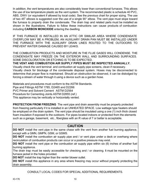
In addition, the vent temperatures are also considerably lower than conventional furnaces. This allowsthe use of low temperature plastic as the vent system. The recommended plastic is schedule 40 PVC,ABS, DWV (or equivalent if allowed by local code). See the previous chart for proper sizing. The useof two 45 o elbows is suggested over the use of a single 90° elbow. The vent pipe must slope towardthe furnace to properly drain the condensate. The drain trap and related parts must be installed asshown in the illustrations. Failure to follow these instructions can cause products of combustionincluding CARBON MONOXIDE entering the dwelling.IF THIS FURNACE IS INSTALLED IN AN ATTIC OR SIMILAR AREA WHERE CONDENSATEOVERFLOW MAY BE A PROBLEM, AN AUXILIARY DRAIN PAN MUST BE INSTALLED UNDERTHE FURNACE WITH THE AUXILIARY DRAIN LINES ROUTED TO THE OUTDOORS TOPREVENT WATER DAMAGE CAUSED BY LEAKS.THE COMBUSTION PRODUCTS AND MOISTURE IN THE FLUE GASES WILL CONDENSE. THECONDENSATE MAY FREEZE ON THE EXTERIOR WALL AND SURROUNDING SURFACES.SOME DISCOLORATION OR ETCHING IS TO BE EXPECTED.THE VENT AND COMBUSTION AIR SUPPLY PIPES MUST BE INSPECTED ANNUALLY.Visually check the vent terminal and combustion air supply pipe screens, clean if necessary.Visually check for blockage of the condensate disposal system. Hoses may be disconnected todetermine that proper flow is maintained. Should an obstruction be observed, it can be dislodged byforcing a stream of water through it using a device such as a garden hose.Materials and procedures must conform to the ASTM Standards.Pipe and Fittings ASTM 1785, D2465 and D2266PVC Primer and Solvent Cement ASTM D2564Procedure for Cementing Joints ASTM D2855 (ref.)This appliance may be vertically or horizontally vented.PROTECTION FROM FREEZING The vent pipe and drain assembly must be properly protectedfrom freezing particularly if it is installed in an UNHEATED SPACE. Low wattage type heaters shouldbe employed on the drain system. The vent pipe should be insulated using a one (1) inch thick closedfoam insulation if exposed to the outdoors. For pipes located indoors or protected from the elementssuch as a garage, basement, etc., fiberglass with an R value of 7 or better is acceptable.CAUTIONDO NOT install the vent pipe in the same chase with the vent from another fuel burning appliance,except with a GMN, GMPN, GSM, or GSMS.DO NOT install the combustion air supply pipe and / or vent pipe under a deck or overhang whererecirculation of combustion products can occur or a positive pressure may exist.DO NOT install the vent pipe or the combustion air supply pipe within six (6) inches of another fuelburning appliance.The drain trap must be easily accessible for checking and / or cleaning. It must be mounted on thefurnace jacket in the holes provided.DO NOT install the trap higher than the venter blower outlet.DO NOT install this appliance in any area where freezing may occur without properly protecting thedrain assembly.CONSULT LOCAL CODES FOR SPECIAL ADDITIONAL REQUIREMENTS.IO-176 10