INSTALLATION & OPERATING INSTRUCTIONS ... - Johnstone Supply
INSTALLATION & OPERATING INSTRUCTIONS ... - Johnstone Supply
INSTALLATION & OPERATING INSTRUCTIONS ... - Johnstone Supply

Create successful ePaper yourself
Turn your PDF publications into a flip-book with our unique Google optimized e-Paper software.
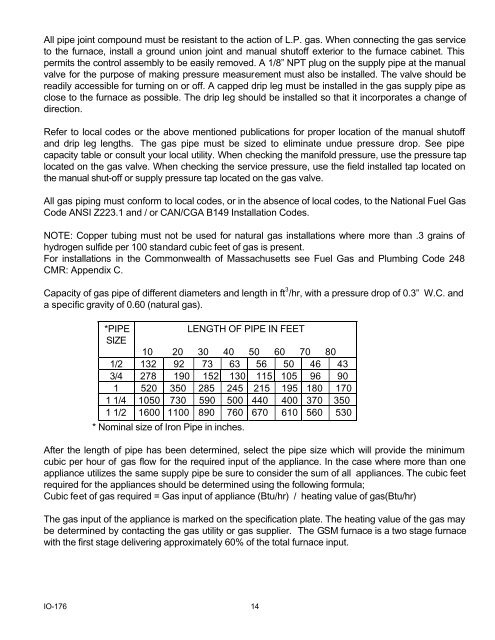
All pipe joint compound must be resistant to the action of L.P. gas. When connecting the gas serviceto the furnace, install a ground union joint and manual shutoff exterior to the furnace cabinet. Thispermits the control assembly to be easily removed. A 1/8” NPT plug on the supply pipe at the manualvalve for the purpose of making pressure measurement must also be installed. The valve should bereadily accessible for turning on or off. A capped drip leg must be installed in the gas supply pipe asclose to the furnace as possible. The drip leg should be installed so that it incorporates a change ofdirection.Refer to local codes or the above mentioned publications for proper location of the manual shutoffand drip leg lengths. The gas pipe must be sized to eliminate undue pressure drop. See pipecapacity table or consult your local utility. When checking the manifold pressure, use the pressure taplocated on the gas valve. When checking the service pressure, use the field installed tap located onthe manual shut-off or supply pressure tap located on the gas valve.All gas piping must conform to local codes, or in the absence of local codes, to the National Fuel GasCode ANSI Z223.1 and / or CAN/CGA B149 Installation Codes.NOTE: Copper tubing must not be used for natural gas installations where more than .3 grains ofhydrogen sulfide per 100 standard cubic feet of gas is present.For installations in the Commonwealth of Massachusetts see Fuel Gas and Plumbing Code 248CMR: Appendix C.Capacity of gas pipe of different diameters and length in ft 3 /hr, with a pressure drop of 0.3” W.C. anda specific gravity of 0.60 (natural gas).*PIPELENGTH OF PIPE IN FEETSIZE10 20 30 40 50 60 70 801/2 132 92 73 63 56 50 46 433/4 278 190 152 130 115 105 96 901 520 350 285 245 215 195 180 1701 1/4 1050 730 590 500 440 400 370 3501 1/2 1600 1100 890 760 670 610 560 530* Nominal size of Iron Pipe in inches.After the length of pipe has been determined, select the pipe size which will provide the minimumcubic per hour of gas flow for the required input of the appliance. In the case where more than oneappliance utilizes the same supply pipe be sure to consider the sum of all appliances. The cubic feetrequired for the appliances should be determined using the following formula;Cubic feet of gas required = Gas input of appliance (Btu/hr) / heating value of gas(Btu/hr)The gas input of the appliance is marked on the specification plate. The heating value of the gas maybe determined by contacting the gas utility or gas supplier. The GSM furnace is a two stage furnacewith the first stage delivering approximately 60% of the total furnace input.IO-176 14