INSTALLATION MANUAL
INSTALLATION MANUAL
INSTALLATION MANUAL

You also want an ePaper? Increase the reach of your titles
YUMPU automatically turns print PDFs into web optimized ePapers that Google loves.
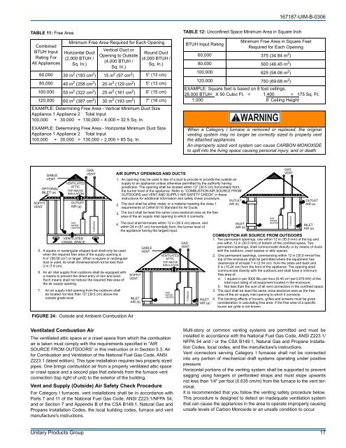
167187-UIM-B-0306TABLE 11: Free AreaCombinedBTUH InputRating ForAll AppliancesMinimum Free Area Required for Each OpeningHorizontal Duct(2,000 BTUH /Sq. In.)Vertical Duct orOpening to Outside(4,000 BTUH /Sq. In.)Round Duct(4,000 BTUH /Sq. In.)60,000 30 in 2 (193 cm 2 ) 15 in 2 (97 cm 2 ) 5” (13 cm)80,000 40 in 2 (258 cm 2 ) 20 in 2 (129 cm 2 ) 5” (13 cm)100,000 50 in 2 (322 cm 2 ) 25 in 2 (161 cm 2 ) 6” (15 cm)120,000 60 in 2 (387 cm 2 ) 30 in 2 (193 cm 2 ) 7” (18 cm)EXAMPLE: Determining Free Area - Vertical Minimum Duct SizeAppliance 1 Appliance 2 Total Input100,000 + 30,000 = 130,000 ÷ 4,000 = 32.5 Sq. In.EXAMPLE: Determining Free Area - Horizontal Minimum Duct SizeAppliance 1 Appliance 2 Total Input100,000 + 30,000 = 130,000 ÷ 2,000 = 65 Sq. In.TABLE 12: Unconfined Space Minimum Area in Square InchBTUH Input RatingMinimum Free Area in Square FeetRequired for Each Opening60,000 375 (34.84 m 2 )80,000 500 (46.45 m 2 )100,000 625 (58.06 m 2 )120,000 750 (69.68 m 2 )EXAMPLE: Square feet is based on 8 foot ceilings.28,000 BTUH X 50 Cubic Ft. = 1,400 = 175 Sq. Ft.1,000 8’ Ceiling HeightWhen a Category I furnace is removed or replaced, the originalventing system may no longer be correctly sized to properly ventthe attached appliances.An improperly sized vent system can cause CARBON MONOXIDEto spill into the living space causing personal injury, and or death.SOFFITVENTGABLEVENTOPTIONALINLET (a)VENTILATEDATTICTOP ABOVEINSULATIONOUTLETAIR (a)GASWATERHEATERVENTILATEDCRAWL SPACEGASVENT5. A square or rectangular shaped duct shall only be usedwhen the required free area of the supply opening is2 29 in (58.06 cm ) or larger. When a square or rectangularduct is used, its small dimensionshall not be less than3 in (7.6 cm).6. An air inlet supply from outdoors shall be equipped witha means to prevent the direct entry of rain and wind.Such means shall not reduce the required free area ofthe air supply opening.7. An air supply inlet opening from the outdoors shallbe located not less than 12” (30.5 cm) above theoutside grade level.FIGURE 24: Outside and Ambient Combustion AirFURNACEAIR SUPPLY OPENINGS AND DUCTS1. An opening may be used in lieu of a duct to provide to provide the outside airsupply to an appliance unless otherwise permitted by the authority havingjurisdiction. The opening shall be located within 12” (30.5 cm) horizontally from,the burner level of the appliance. Refer to “COMBUSTION AIR SOURCE FROMOUTDOORS and VENT AND SUPPLY AIR SAFETY CHECK” in theseinstructions for additional information and safety check procedure.2. The duct shall be either metal, or a material meeting the class 1requirements of CAN4-S110 Standard for Air Ducts.3. The duct shall be least the same cross-sectional area as the freearea of the air supply inlet opening to which it connects.4.The duct shall terminate within 12 in (30.5 cm) above, andwithin 24 in (61 cm) horizontally from, the burner level ofthe appliance having the largest input.SOFFITVENTINLETAIR (b)GABLEVENTVENTILATEDATTICTOP ABOVEINSULATIONGASWATERHEATERGASVENTFURNACEINLETAIR (a)OUTLETAIR (b)INLETAIR (b)GASWATERHEATERGASVENTFURNACEOUTLETAIR (a)INLETAIR (a)COMBUSTION AIR SOURCE FROM OUTDOORS1. Two permanent openings, one within 12 in (30.5 mm) of the top andone within 12 in (30.5 mm) of bottom of the confined space, Twopermanent openings, shall communicate directly or by means of ductswith the outdoors, crawl spaces or attic spaces.2. One permanent openings, commencing within 12 in (30.5 mm)of thetop of the enclosure shall be permitted where the equipment hasclearances of at least 1 in (2.54 cm) from the sides and back and6 in (15.24 cm) from the front of the appliance. The opening shallcommunicate directly with the outdoors and shall have a minimumfree area of:3a. 1 square in per 3000 Btu per hour (6.45 cm per 0.879 kW) of thetotal input rating of all equipment located in the enclosure.b. Not less than the sum of all vent connectors in the confined space.3. The duct shall be least the same cross-sectional area as the freearea of the air supply inlet opening to which it connects.4. The blocking effects of louvers, grilles and screens must be givenconsideration in calculating free area. If the free area of a specificlouver aor grille is not known.Ventilated Combustion AirThe ventilated attic space or a crawl space from which the combustionair is taken must comply with the requirements specified in “AIRSOURCE FROM OUTDOORS” in this instruction or in Section 5.3, Airfor Combustion and Ventilation of the National Fuel Gas Code, ANSIZ223.1 (latest edition). This type installation requires two properly sizedpipes. One brings combustion air from a properly ventilated attic spaceor crawl space and a second pipe that extends from the furnace ventconnection (top right of unit) to the exterior of the building.Vent and Supply (Outside) Air Safety Check ProcedureFor Category I furnaces, vent installations shall be in accordance withParts 7 and 11 of the National Fuel Gas Code, ANSI Z223.1/NFPA 54,and or Section 7 and Appendix B of the CSA B149.1, Natural Gas andPropane Installation Codes, the local building codes, furnace and ventmanufacture's instructions.Multi-story or common venting systems are permitted and must beinstalled in accordance with the National Fuel Gas Code, ANSI Z223.1/NFPA 54 and / or the CSA B149.1, Natural Gas and Propane InstallationCodes, local codes, and the manufacture's instructions.Vent connectors serving Category I furnaces shall not be connectedinto any portion of mechanical draft systems operating under positivepressure.Horizontal portions of the venting system shall be supported to preventsagging using hangers or perforated straps and must slope upwardsnot less than 1/4" per foot (0.635 cm/m) from the furnace to the vent terminal.It is recommended that you follow the venting safety procedure below.This procedure is designed to detect an inadequate ventilation systemthat can cause the appliances in the area to operate improperly causingunsafe levels of Carbon Monoxide or an unsafe condition to occur.Unitary Products Group 17