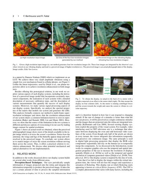
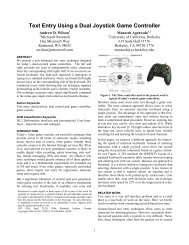
2 • F. <strong>Berthouzoz</strong> and R. Fattal(a) High-resolution input image(b) One of the four low-resolution imagesgenerated <strong>by</strong> our method(c) Perceived image on the vibrating display(showing four low-resolution images)Fig. 1. Given a high resolution input image (a), our method generates four low-resolution images (b). These four images are integrated <strong>by</strong> the observer’s eyewhen viewed on our vibrating display and lead to a perceived image of higher resolution (c). The perceived image is an actual photograph taken of the display.Image credits: Eddy Van Leuven.in a patent <strong>by</strong> Damera-Venkata [2009] which we implement on anLCD. We achieve these very small amplitude vibrations using asimple low-cost mechanism found in cellular phones, see Figure 2.Unlike the linear trajectories, used <strong>by</strong> Didyk et al., our planar trajectoriesallow us to achieve resolution enhancement in both imageaxes.Besides offering this prototypical solution, in our work we explorevarious aspects of such display systems, including the derivationof a perceived image model that incorporates accurately measuredcomponents, the realization of such systems with a detaileddescription of necessary calibration steps, and the description ofvarious measurements that quantify the success of such displaysystems. Moreover, we study various signal processing aspects ofour display system. Specifically, we analyze the spectral propertiesof the matrix that models our system and generates the LRIs.This analysis formally connects our method to multi-frame superresolutiontechniques and shows that the resolution enhancementof our system shares a common limitation known to exist in superresolution[Baker and Kanade 2000; Lin and Shum 2001]. However,we show that the source of the limitation in the two systems isdifferent and discuss options of overcoming it in our case <strong>by</strong> tradingimage contrast for spatial resolution.Figure 1 shows an actual result we obtained, where the perceived(photographed) image shows most of the details available in the inputimage which is at twice the screen’s resolution. Notice how theantennae, the wings and legs of the butterfly appear sharp and wellresolvedin the perceived image. To conclude, our system allowsus to match images of twice the screen resolution without movingthem across the screen. Thus, it offers a practical solution to resolutionenhancement. We discuss other potential mechanical andoptical alternatives for our implementation.2. RELATED WORKIn addition to the works discussed above our display system buildson several other works from different areas.Perception-Based Techniques. Our eyes periodically sampleinformation of images projected onto the retina and integrate thisinformation temporally to produce the perceived image. It takes theeye a certain amount of time to process the sampled informationcolumnsdisplaymotorshaftweightFig. 2. To vibrate the display, we attach to the back of it a motor with aweight connected at an offset to the motor shaft (right). We then mount thedisplay on four columns (left). As the motor is rotating centrifugal forcespull the screen towards the weight and cause the screen to vibrate in a circulartrajectory.and it is therefore limited in how fast it can respond to changingstimuli. If the rate of change of a stimulus is faster than what theeye can process, it will be perceived as a single continuous stimulusand the images that are projected onto the retina are integrated temporally[Kalloniatis and Luu 2009]. Several existing display systemsexploit this property of the visual system. For example, videointerlacing used in CRT television sets is a technique that alternatesbetween displaying the even and odd horizonal video scanlinesof the screen. Even though only half of the pixels are shownat every instant, the viewer integrates this information temporallyand perceives one continuous image. The same principle is usedin digital light processing projectors that display the RGB colorcomponents sequentially and rely on the human eye to temporallymerge the components. As we discussed in the Introduction, recentworks in computer graphics also use the temporal and spatial integrationproperties of the eye to increase the resolution of displaysspatially [Didyk et al. 2010a] as well as the temporal and spatialresolution of computer-generated videos [Didyk et al. 2010b; Templinet al. 2011]. Our display system is inspired <strong>by</strong> this line of work.Note that if we fail to display the images within the retinal integrationtime, the viewer will not fuse the images and experience asensation of flickering. This display rate at which flickering startsappearing is known as critical flicker frequency (CFF). The CFF isa complex phenomenon that varies with many factors, including theACM Transactions on Graphics, Vol. VV, No. N, Article XXX, Publication date: Month YYYY.
<strong>Resolution</strong> <strong>Enhancement</strong> <strong>by</strong> <strong>Vibrating</strong> <strong>Displays</strong> • 3size of the stimulus pattern [Mäkelä et al. 1994; McKee and Taylor1984] and its intensity [Norwich 1993]. Didyk et al. [2010a] proposean effective post-processing method to prevent flickering inthe setting of high refresh-rate displays, but their solution may reducethe amount resolution enhancement gained. While we do notaddress the problem of flickering in our work, Didyk et al.’s methodwould apply to our setting without any modification.Projector Super-Sampling. Jaynes and Ramakrishnan [2003]exploit the ability to overlap images projected from multiple projectorsto enhance resolution. They generate one LRI for eachprojector in a sub-optimal greedy approach. Damera-Venkata andChang [2007b] push this idea farther and derive an optimal LRIgeneration algorithm for the same setting of multiple projectors.They also analyze how non-uniform displacements between theLRIs influences the resolution enhancement they obtain [Damera-Venkata and Chang 2007a]. Finally, they show that projector superresolutionmay be achieved <strong>by</strong> designing a bank of alias-cancelingrendering filters and derive a practical non-iterative filter bank approachfor their previous technique [Damera-Venkata and Chang2009]. Our work is similar to multi-projector techniques in thesense that we also generate an optimal set of LRIs from a highresolutioninput image. But in our case, the target device is a singledisplay. Our method therefore does not have to account for intraandinter-projection variations that require careful geometric, photometricand color calibrations. Instead, we are able to achieve resolutionenhancement <strong>by</strong> exploiting the temporal integration propertiesof the human eye. As we noted earlier, the idea of displayingshifted images using a single display was also described <strong>by</strong> Allenand Ulichney for projectors and in [Damera-Venkata 2009]. However,Allen and Ulichney do not further explore how to optimallygenerate the displayed LRIs, nor do they discuss the limits of suchan approach. Damera-Venkata’s patent merely describes the ideaof such a display system with no analysis, evaluation or theoreticalexplanation. Finally, Napoli et al. [2008] suggest an alternativeapproach where they use a single projector and deviate the lightrapidly using an aperture array. This allows them to display up to300 non-overlapping LRIs that form a new higher resolution grid.In contrast, our approach uses the overlaps between the LRIs togain resolution.Multi-frame Super-<strong>Resolution</strong>. Our work is also closely relatedto super-resolution techniques [Irani and Peleg 1990; Parket al. 2003], where a high-resolution image is computed from a setof LRIs taken at different translational offsets. We have the oppositegoal of super-resolution techniques; given a high-resolution image,we compute a set of LRIs and display them at different offsets. Previousstudies [Baker and Kanade 2000; Lin and Shum 2001] showthat super-resolution has a practical limit on the maximal magnificationfactor it can achieve due to the strong amplification of noiseat high-frequencies. We formally link our construction of the LRIsto super-resolution and analyze and deduce limits on the resolutionenhancement achievable on a given display. Our work shares similaritieswith the work of Ben-Ezra et al. [2004] on super-resolutiontechniques for video enhancement. In this work, they also use physicalmotion and shift the camera sensor using micro-actuators toobtain precise offsets between the LRIs.3. METHODIn order to compute the set of LRIs that will optimally displaythe high-frequency content of the input high-resolution image, wemodel the perceived image generated <strong>by</strong> our proposed imaging system.We start this derivation <strong>by</strong> defining the continuous functionthat describes how a single image L viewed on a stationary displayappears on the screen,N ∫ TV static (y) = ∑ P(y − x,t)L(x)dt, (1)x=1 0where x is an integer pixel index, N is the number of pixels in L,y is a real-valued point on the screen plane, T is a period in timeand P is the point spread function (PSF) of the display. The pointspread function describes the shape of a single-pixel turned on asit appears on the display at a given time. We allow P to dependon time in order to account for frame-rate control, overdrive andother techniques typically used <strong>by</strong> modern displays to control theappearance of a pixel over time. The static image is an aggregateover time that the viewer perceives.<strong>Vibrating</strong> the display along some periodic trajectory and rapidlydisplaying several images within each period, that falls below theretinal integration time, yields the following perceived imageN ∫ TV vibrating (y) = ∑ P(y − x − ϕ(t),t)L t (x)dt, (2)x=1 0where T is the time period of a single vibration and ϕ(t) indicatesthe display position as it moves along the trajectory at time t. However,since we display a small finite number of images, L t ceases tobe a continuous function in time and the above becomes∫ ti+1N nN nV vibrating (y)= ∑ ∑ P(y−x−ϕ(t),t)L i (x)dt=x=1 i=1 t i∑ ∑S i (y−x)L i (x),x=1 i=1(3)where n is the number of LRIs andS i (y − x) =∫ ti+1t iP(y − x − ϕ i (t),t)dt (4)where [t i ,t i+1 ] is the time interval during which the i-th image isdisplayed. We call the time-averaged display point spread functions,S i , smeared point spread functions (SPSFs). Note that theSPSFs are aggregates over time and thus implicitly take into accountvariations of P over time. In Figure 3 we show an example ofa static PSF, the trajectory along one quarter of a circular trajectory(ϕ i shown <strong>by</strong> the red curve), and the result of smearing the PSFalong this trajectory (S i ). In Section 3.1 we explain how we acquirethese PSFs for our display.We compute an optimal approximation to a given high-resolutionimage H(y), in the L 2 sense, through the following minimizationproblem∫ ( N n2dy.minL 1 ...L n∑ ∑S i (y−x)L i (x) − H(y))(5)x=1 i=1In practice, we solve this minimization problem on a discretegrid, in which the y coordinate is discretized. The input image Hand the SPSFs are specified at this grid. We call it the computationalgrid and set its resolution to be high enough such that theshape of the SPSFs is properly captured. As we explain in Section3.1, in our implementation we use a computational resolutionthat is eight times higher than the LRIs’ resolution. Note that settingthe computational resolution to eight does not mean that wewill be able to achieve a resolution enhancement <strong>by</strong> that factor. Wedistinguish between the computational resolution used for computationalpurposes only, and the target resolution which indicatesthe amount of true resolution enhancement that we can obtain withour method. The target resolution is dictated <strong>by</strong> the number andthe arrangement of the LRIs on the display, as well as other factorsACM Transactions on Graphics, Vol. VV, No. N, Article XXX, Publication date: Month YYYY.