

Overvoltages & Insulation Coordination - engineering site
Overvoltages & Insulation Coordination - engineering site
Overvoltages & Insulation Coordination - engineering site

You also want an ePaper? Increase the reach of your titles
YUMPU automatically turns print PDFs into web optimized ePapers that Google loves.
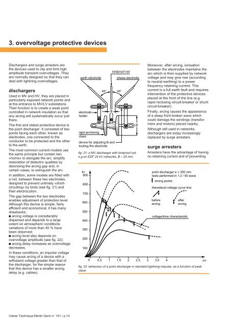
3. overvoltage protective devicesDischargers and surge arresters arethe devices used to clip and limit highamplitude transient overvoltages. Theyare normally designed so that they candeal with lightning overvoltages.dischargersUsed in MV and HV, they are placed inparticularly exposed network points andat the entrance to MV/LV substations.Their function is to create a weak pointcontrolled in network insulation so thatany arcing will systematically occur justthere.The first and oldest protective device isthe point discharger. It consisted of twopoints facing each other, known aselectrodes, one connected to theconductor to be protected and the otherto the earth.The most common current models usethe same principle but contain two«horns» to elongate the arc, simplifyrestoration of dielectric qualities bydeionising the arcing gap and, incertain cases, to extinguish the arc.In addition, some models are fitted witha rod, between these two electrodes,designed to prevent untimely «shortcircuiting»by birds (see fig. 21) andtheir electrocution.The gap between the two electrodesenables adjustment of protection level.Although this device is simple, fairlyefficient and economical, it has manydrawbacks:■ arcing voltage is considerablydispersed and depends to a largeextent on atmospheric conditions:variations of more than 40 % havebeen observed;■ arcing level also depends onovervoltage amplitude (see fig. 22);■ arcing delay increases as overvoltagedecreases.In these conditions, an impulse voltagemay cause arcing of a device with awithstand voltage greater than that ofthe discharger, for the simple reasonthat this device has a smaller arcingdelay (e.g. cables).earth electrodeelectrodeholderrigid anchoringchaindevice for adjusting B andlocking the electrodebirdproof rod45° 45°Bphase electrodefig. 21: a MV discharger with birdproof rode.g.on EDF 24 kV networks, B ≈ 25 mm.kv90080070060050040030020010000.5 1 1.5 2 2.5 3 3.5 4ØMoreover, after arcing, ionisationbetween the electrodes maintains thearc which is then supplied by networkvoltage and may give rise (accordingto neutral earthing) to a powerfrequency retaining current. Thiscurrent is a full earth fault and requiresintervention of the protective devicesplaced at the front of the line (e.g.rapid reclosing circuit-breaker or shuntcircuit-breaker).Finally, arcing causes the appearanceof a steep front broken wave whichcould damage the windings (transformersand motors) placed nearby.Although still used in networks,dischargers are today increasinglyreplaced by surge arresters.surge arrestersArresters have the advantage of havingno retaining current and of preventingpoint discharger e = 350 mmtests performed in 1.2 / 50 wavearcing pointstheoretical voltage curve line:beforearcingafterarcingvoltage/time characteristicfig. 22: behaviour of a point discharger in standard lightning impulse, as a function of peakvalue.µsCahier Technique Merlin Gerin n° 151 / p.14


