Download - Keystone
Download - Keystone
Download - Keystone

You also want an ePaper? Increase the reach of your titles
YUMPU automatically turns print PDFs into web optimized ePapers that Google loves.
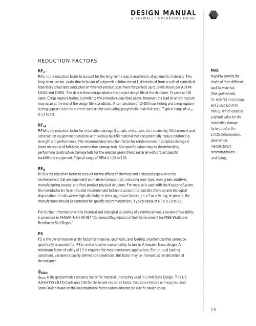
DESIGN MANUAL& KEYWALL OPERATING GUIDEREDUCTION FACTORSRF crRFcr is the reduction factor to account for the long-term creep characteristic of polymetric materials. Thelong-term tension-strain-time behavior of polymeric reinforcement is determined from results of controlledlaboratory creep tests conducted on finished-product specimens for periods up to 10,000 hours per ASTMD5262 and D6992. The data is then extrapolated to the project design life of the structure, 75 years or 100years. Creep rupture testing is similar to the procedure described above, however, the load at which rupturemay occur at the end of the design life is predicted. A combination of 10,000 hour testing and creep rupturetesting appears to be the current standard for evaluating geosynthetic material creep. Typical range of RF cris 1.4 to 5.0.RF idRFid is the reduction factor for installation damage (i.e., cuts, nicks, tears, etc.) created by fill placement andconstruction equipment operations with various backfill material that can potentially reduce reinforcingstrength and performance. The recommended reduction factor for reinforcement installation damage isbased on results of full-scale construction damage tests. Site specific values may be determined byperforming construction damage tests for the selected geosynthetic material with project specificbackfill and equipment. Typical range of RFid is 1.05 to 2.00.Note:KeyWall permits thechoice of three differentbackfill materials(fine-grained soils,3⁄4- inch (20 mm) minus,and 2 inch (50 mm)minus), which establisha default value for theinstallation damagefactors used in theLTDS determination,based on themanufacturer’srecommendationsand testing.RF dRFd is the reduction factor to account for the effects of chemical and biological exposure to thereinforcement that are dependent on material composition, including resin type, resin grade, additives,manufacturing process, and final product physical structure. For most soils used with the <strong>Keystone</strong> System,the manufacturers have included recommended factors to account for possible chemical and biologicaldegradation. In soils where high alkalinity or other aggressive factors (ph < 3 or > 9) may be present, themanufacturer should be contacted for specific recommendations. Typical range of RFd is 1.0 to 2.0.For further information on the chemical and biological durability of a reinforcement, a review of durabilityis presented in FHWA-NHI-09-087 “Corrosion/Degradation of Soil Reiforcement for MSE Walls andReinforced Soil Slopes.”FSFS is the overall tension safety factor for material, geometric, and loading uncertainties that cannot bespecifically accounted for. FS is similar to other overall safety factors in Allowable Stress design. Aminimum factor of safety of 1.5 is required for most permanent applications. For unusual loadingconditions, variable or poorly defined soil conditions, this factor may be increased at the discretion ofthe designer.φ GEOφ GEO is the geosynthetic resistance factor for material uncertainty used in Limit State Design. The USAASHTO LRFD Code uses 0.90 for the tensile resistance factor. Resistance factors will vary in LimitState Design based on the load/resistance factor system adopted by specific design codes.2.3