Download - Keystone
Download - Keystone
Download - Keystone

You also want an ePaper? Increase the reach of your titles
YUMPU automatically turns print PDFs into web optimized ePapers that Google loves.
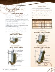
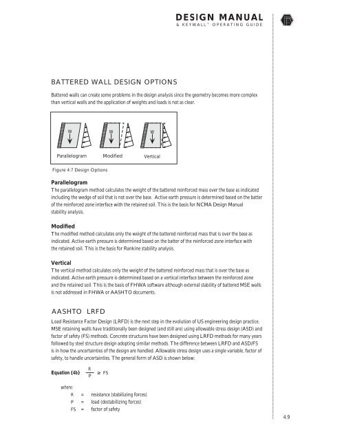
DESIGN MANUAL& KEYWALL OPERATING GUIDEBATTERED WALL DESIGN OPTIONSBattered walls can create some problems in the design analysis since the geometry becomes more complexthan vertical walls and the application of weights and loads is not as clear.W W WParallelogram Modified VerticalFigure 4:7 Design OptionsParallelogramThe parallelogram method calculates the weight of the battered reinforced mass over the base as indicatedincluding the wedge of soil that is not over the base. Active earth pressure is determined based on the batterof the reinforced zone interface with the retained soil. This is the basis for NCMA Design Manualstability analysis.ModifiedThe modified method calculates only the weight of the battered reinforced mass that is over the base asindicated. Active earth pressure is determined based on the batter of the reinforced zone interface withthe retained soil. This is the basis for Rankine stability analysis.VerticalThe vertical method calculates only the weight of the battered reinforced mass that is over the base asindicated. Active earth pressure is determined based on a vertical interface between the reinforced zoneand the retained soil. This is the basis of FHWA software although external stability of battered MSE wallsis not addressed in FHWA or AASHTO documents.AASHTO LRFDLoad Resistance Factor Design (LRFD) is the next step in the evolution of US engineering design practice.MSE retaining walls have traditionally been designed (and still are) using allowable stress design (ASD) andfactor of safety (FS) methods. Concrete structures have been designed using LRFD methods for many yearsfollowed by steel structure design adopting similar methods. The difference between LRFD and ASD/FSis in how the uncertainties of the design are handled. Allowable stress design uses a single variable, factor ofsafety, to handle uncertainties. The general form of ASD is shown below:Equation (4b)RP≥ FSwhere:R = resistance (stabilizing forces)P = load (destabilizing forces)FS = factor of safety4.9