Banks Six-Gun® Diesel Tuner - Bankspower - Banks Power
Banks Six-Gun® Diesel Tuner - Bankspower - Banks Power
Banks Six-Gun® Diesel Tuner - Bankspower - Banks Power

You also want an ePaper? Increase the reach of your titles
YUMPU automatically turns print PDFs into web optimized ePapers that Google loves.
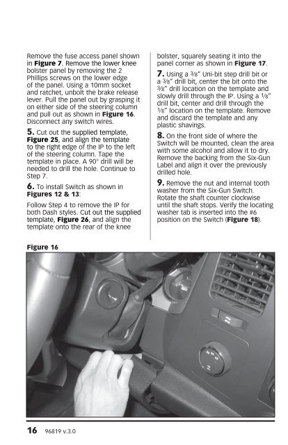
Remove the fuse access panel shownin Figure 7. Remove the lower kneebolster panel by removing the 2Phillips screws on the lower edgeof the panel. Using a 10mm socketand ratchet, unbolt the brake releaselever. Pull the panel out by grasping iton either side of the steering columnand pull out as shown in Figure 16.Disconnect any switch wires.5. Cut out the supplied template,Figure 25, and align the templateto the right edge of the IP to the leftof the steering column. Tape thetemplate in place. A 90° drill will beneeded to drill the hole. Continue toStep 7.6. To install Switch as shown inFigures 12 & 13:Follow Step 4 to remove the IP forboth Dash styles. Cut out the suppliedtemplate, Figure 26, and align thetemplate onto the rear of the kneebolster, squarely seating it into thepanel corner as shown in Figure 17.7. Using a 3 ⁄8” Uni-bit step drill bit ora 3⁄8” drill bit, center the bit onto the3⁄8” drill location on the template andslowly drill through the IP. Using a 1⁄8”drill bit, center and drill through the1⁄8” location on the template. Removeand discard the template and anyplastic shavings.8. On the front side of where theSwitch will be mounted, clean the areawith some alcohol and allow it to dry.Remove the backing from the <strong>Six</strong>-GunLabel and align it over the previouslydrilled hole.9. Remove the nut and internal toothwasher from the <strong>Six</strong>-Gun Switch.Rotate the shaft counter clockwiseuntil the shaft stops. Verify the locatingwasher tab is inserted into the #6position on the Switch (Figure 18).Figure 1616 96819 v.3.0